InfraTec VarioCAM User Manual
Thermographic system high resolution
Hide thumbs
Also See for VarioCAM:
- Operating instructions manual (111 pages) ,
- User manual (82 pages) ,
- Short user manual (2 pages)
Table of Contents
Advertisement
VarioCAM
incl. IRBIS
InfraTec GmbH
Infrarotsensorik und Messtechnik
Gostritzer Straße 61 – 63
01217 Dresden/GERMANY
®
high resolution
®
remote 3.0 software description
User Manual
Last reviewed: December 2012
Phone
+49 351 871-8615
Fax
+49 351 871-8727
E-mail
service@InfraTec.de
www.InfraTec.de
© InfraTec 2012
(All the stated product names and trademarks remain in
property of their respective owners.)
Advertisement
Table of Contents

Related Manuals for InfraTec VarioCAM


Summary of Contents for InfraTec VarioCAM
-
Page 1: User Manual
VarioCAM high resolution incl. IRBIS ® remote 3.0 software description User Manual Last reviewed: December 2012 © InfraTec 2012 InfraTec GmbH Phone +49 351 871-8615 (All the stated product names and trademarks remain in Infrarotsensorik und Messtechnik +49 351 871-8727 property of their respective owners.) -
Page 3: Table Of Contents
User Manual for the Thermographic System VarioCAM ® high resolution Table of Contents Table of Contents Introduction ........................1 Advice on Device Safety ....................3 Technical Description ....................5 Operating Principle ......................... 5 Description of the Functional Units ....................5 Technical Data .......................... - Page 4 ® Hardware and Software Installation for VarioCAM hr*........... 67 Fundamentals ..........................67 Hardware Components ........................ 67 ® Installation of the FireWire Driver for the VarioCAM hr .............. 68 ® Operating Software IRBIS remote 3.0* ..............75 10.1 Programme Start .......................... 75 10.2...
-
Page 5: Introduction
Jenoptik and InfraTec GmbH. This instruction manual was compiled with the necessary diligence. No liability is accepted for damage arising from non-observance of the information contained in this instruction manual. - Page 6 User Manual for the Thermographic System VarioCAM ® high resolution 1. Introduction ® ® VarioCAM high resolution (hereinafter VarioCAM hr) is a modern thermographic system for the precise, quick and non-contact measurement of surface temperatures of objects. ® VarioCAM hr has been designed for universal use and can be applied as both a mobile and a stationary system for measuring and saving temperature data.
-
Page 7: Advice On Device Safety
User Manual for the Thermographic System VarioCAM ® high resolution 2. Advice on Device Safety Advice on Device Safety General ® The VarioCAM hr is a high-quality, thoroughly calibrated optical measuring instrument. Handle it with appropriate care. Avoid soiling it, particularly its optical surfaces. - Page 8 Under certain conditions, it cannot be excluded, even when the system is switched off, that the ® detector may be damaged when directed into sunlight. Therefore, when the VarioCAM hr is not in use, the lens must be capped with the protective cover included.
-
Page 9: Technical Description
User Manual for the Thermographic System VarioCAM ® high resolution 3. Technical Description Technical Description Operating Principle ® The VarioCAM hr is a thermographic system for the long wave infrared spectral range (LWIR) of (7.5 ... 14) µm. The lens images the object scene onto a microbolometer array at a resolution of (640 x 480), (384 x 288) or (320 x 240) pixels. - Page 10 User Manual for the Thermographic System VarioCAM ® high resolution 3. Technical Description Thermographic system of resolution (384 x 288) pixels lens focal length (mm) min. focus (m) IFOV (mrad) FOV (°) wide-angle lens 12.5 (57 x 44) standard lens...
- Page 11 User Manual for the Thermographic System VarioCAM ® high resolution 3. Technical Description Image processing electronics Real-time image processing with the following essential functions (depending on the equipment) is implemenmted with the help of an FPGA (Field Programmable Gate Array) and an embedded PC (modular compact internal PC): ■...
-
Page 12: Power Supply
User Manual for the Thermographic System VarioCAM ® high resolution 3. Technical Description Power supply ® The VarioCAM hr has the following power supply options: ■ External power supply unit 12 V* ■ Li-ion rechargeable battery 7.2 V or ■... -
Page 13: Technical Data
2 G, IEC 68-2-6 ® * (Properties and technical specifications are dependent on the camera configuration and vary in the equipment packages VarioCAM hr basic, inspect and research. Design and specifications are subject to permanent improvement; subject to changes in the sense of technical progress.) User Manual ©... -
Page 14: Unpacking And Checking
User Manual for the Thermographic System VarioCAM ® high resolution 4. Unpacking and Checking Unpacking and Checking ® Upon receipt of the VarioCAM hr, please check for its completeness and that components are not damaged. The supplier must immediately be informed of any damage. -
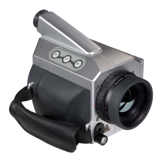
Page 15: Description Of Camera Parts
User Manual for the Thermographic System VarioCAM ® high resolution 5. Description of Camera Parts Description of Camera Parts Colour TFT WLAN aerial Li-ion battery LEMO socket, 6-pole for: (marked yellow) Headset socket ■ FireWire (IEEE 1394) cable ■ Power supply unit with adapter... -
Page 16: Quick Start
® high resolution 6. Quick Start Quick Start ® The following instructions shall help to quickly familiarise with operating the VarioCAM hr. For obtaining professional results, we recommend to carefully read the entire manual. button (Automatic) button (Temperature spot measurement) button (Stop / Store) Multifunctional joystick ,... -
Page 17: Display
User Manual for the Thermographic System VarioCAM ® high resolution 6. Quick Start initialisation, the Operating LED, initially flashing green, subsequently turning to permanent green, ® signals that the VarioCAM hr is ready for operation in the live mode. Display... -
Page 18: Data Storage
User Manual for the Thermographic System VarioCAM ® high resolution 6. Quick Start Data Storage ■ For Storage of the thermal image press the button. The live image freezes, i.e. camera goes into stop mode. Stop mode Fig. 7 Camera menu in stop mode ■... -
Page 19: Data Transfer To The Computer
User Manual for the Thermographic System VarioCAM ® high resolution 6. Quick Start Data Transfer to the Computer ■ The most frequently used method for data transfer is reading out the SD card with the help of an SD card reader. -
Page 20: Starting Up
User Manual for the Thermographic System VarioCAM ® high resolution 7. Starting up Starting up Shoulder Strap Adjustment How to fix the shoulder strap is explained in the following figures: Fig. 10 Step 1: Fig. 11 Step 2: Fig. 12... -
Page 21: Hand Strap Adjustment
User Manual for the Thermographic System VarioCAM ® high resolution 7. Starting up Hand Strap Adjustment ® VarioCAM hr is designed as a highly portable system for single-handed operation. First adjust the hand strap fixed to the handle according to your needs. Open the clip of the hand strap and adjust the length of the strap, so that you can reach the controls comfortably with your fingers. -
Page 22: Operation Via The Firewire (Ieee 1394) Interface
7. Starting up Operation via the FireWire (IEEE 1394) Interface* ® By means of the following connecting options, the VarioCAM hr can be connected to the PC/notebook. The accessories described are optionally included in the scope pf delivery*. Please follow the instructions, i.e. always plug the FireWire cable into the computer first and then... - Page 23 When connecting the thermographic camera with the PC/notebook for the first time, automatic hardware ® recognition will be activated. Further steps for installing the FireWire (IEEE1394) driver for the VarioCAM ® are described in Chapter 9.3, Installation of the FireWire Driver for the VarioCAM hr, page 68.
-
Page 24: Operation With Breakout Box (Connection Via Rs232)
Operation with Breakout Box (Connection via RS232)* ® The use of the Breakout Box extends the options of connection of the VarioCAM hr. The analog outputs PAL/NTSC-FBAS and S Video as well as the digital RS232 interface are accessible via the Breakout Box. -
Page 25: Trigger Functionality Variocam ® High Resolution
Triggering only affects the 16-bit data transmission via FireWire. A 14-core system cable transmits the ® TTL/CMOS-signal from the interfaces “T1” and “T2” on the Breakout Box to the VarioCAM hr. Use the included trigger cables in order to connect the Breakout Box, see Fig. 24 and Fig. 27. - Page 26 Breakout Box of the power supply is connected to the 6- pin on the (system cable) ® right of the LEMO socket of the VarioCAM hr via adapter P. Adapter P (power supply adapter) is only to be used...
-
Page 27: Operation
User Manual for the Thermographic System VarioCAM ® high resolution 8. Operation Operation Control Elements ® The VarioCAM hr has the following control elements: ■ Membrane keypad on the right top of the camera (keys S, and A) ■ Membrane keypad at the rear button) ■... -
Page 28: Graphical User Interface
Apart from the current temperature, information is displayed via various image elements ® regarding the status of the system and regarding operation control. The VarioCAM hr can be controlled either with the help of the controls on the system or remotely via the RS232 or FireWire*. -
Page 29: Live Mode
User Manual for the Thermographic System VarioCAM ® high resolution 8. Operation The image elements have the following functions: ■ Help display of the active key assignment (basic functions) ■ Logo manufacturerer’s logo JENOPTIK Laser, Optik, Systeme GmbH ■ Status active operating mode of thermal image system ■... - Page 30 User Manual for the Thermographic System VarioCAM ® high resolution 8. Operation button is used to permanently change between the colour palettes in the live mode. The default setting when starting the system is the VarioCAM palette. VarioCAM BlackWhite Iron BlueRed...
-
Page 31: Focus Mode
User Manual for the Thermographic System VarioCAM ® high resolution 8. Operation 8.2.3 Focus Mode In the focus mode, larger or smaller object distances will be focused on by respectively moving the and . The progress bar marked F left of the colour palette shows the relative position of the joystick focus - see Fig. -
Page 32: Spot Editor
User Manual for the Thermographic System VarioCAM ® high resolution 8. Operation For switching off the device, press for a longer period (> 2 s, CL). A power down dialogue will appear Fig. 37). Pressing Enter switches the thermographic system off. - Page 33 User Manual for the Thermographic System VarioCAM ® high resolution 8. Operation The position of the ROI is changed by using the joystick, whereas movements move the ROI vertically up and down, and horizontally left and right (see Fig. 37).
- Page 34 User Manual for the Thermographic System VarioCAM ® high resolution 8. Operation Status "Spoteps" In the "Spoteps" status, the emissivity of a measuring area can be changed from 0.01 to 1.00. Spot editor: “Spoteps” Help for joystick movements for changing the emissivity in 0.01/0.1 increments...
-
Page 35: Stop Mode And Data Storage
(CL), the selection of colour palettes will circulate and can be chosen from. ® In order to save thermal images with the VarioCAM hr, an SD card must have been inserted into the card slot. - Page 36 User Manual for the Thermographic System VarioCAM ® high resolution 8. Operation A possibly write-protected SD card will subsequently be displayed as shown in Fig. 47. In the stop mode, the current thermogram is saved by using the button. Storing it directly out of live (or focus) is possible by pressing the button (SL) for a longer period (quick save).
-
Page 37: The Main Menu
User Manual for the Thermographic System VarioCAM ® high resolution 8. Operation The Main Menu In the live or focus mode, a long press (middle key) on the joystick (EnterL) will open the main menu. Via the main menu, further functions can be called up and other system settings can be made or recalled. - Page 38 User Manual for the Thermographic System VarioCAM ® high resolution 8. Operation Menu item "CMOS-camera"/VIS mode* Fig. 53 Menu "Image" - "CMOS-camera" ® VarioCAM hr comes with an optional colour video camera, which serves the human eye to orientate in the visible spectral range and which can be used for the simultaneous photographic documentation of the measuring situation.
- Page 39 User Manual for the Thermographic System VarioCAM ® high resolution 8. Operation When selecting this function, the video image is displayed black/white independently of the setting in the menu “CMOS-camera” in order to ease the differentiation of the false-colour display of the temperature distribution.
- Page 40 User Manual for the Thermographic System VarioCAM ® high resolution 8. Operation Menu item Palette → Inverse inverts the current palette. If, for example, the BlackWhite palette is selected, the lower temperatures are displayed in black by default and the higher temperatures in white. If the "Inverse"...
- Page 41 User Manual for the Thermographic System VarioCAM ® high resolution 8. Operation Menu item "Image filter" Fig. 61 Menu item "Image" - "Image filter" Using the menu item "Image filter", a filter for the presentation of thermal images can be adjusted. As a filter, a digital low-pass filter of the first order is used.
- Page 42 User Manual for the Thermographic System VarioCAM ® high resolution 8. Operation Menu item "Isotherms.."/Isotherm editor* Fig. 64 Menu “Image” – “Isotherms..” The isotherm editor is started via menu item Image →Isotherms.. (Fig. 64). Isotherms colour-mark ranges of the same temperature. With the help of the isotherm editor it is possible, to design isotherms of different (temperature) “width”...
- Page 43 User Manual for the Thermographic System VarioCAM ® high resolution 8. Operation If an isotherm already exists, a second one is created by pressing TL. Should more than one isotherm exist, will switch to selecting the active isotherm. By using TL, another isotherm can be generated. The possible number of isotherms depends on the model.
-
Page 44: Menu "File
User Manual for the Thermographic System VarioCAM ® high resolution 8. Operation 8.3.2 Menu "File" Fig. 71 Menu "File" Fig. 71 shows the options of the "File" menu. It comprises all functions relating to the file system. The various items are described in the following sections. - Page 45 User Manual for the Thermographic System VarioCAM ® high resolution 8. Operation Fig. 73 Dialogue "Load" – directory structure Fig. 74 Dialogue "Load" - files After selecting "Load file..", the current directory structure with its contents is displayed in a dialogue (see Fig.
- Page 46 User Manual for the Thermographic System VarioCAM ® high resolution 8. Operation Fig. 76 Reloaded image status “Image” Menu item "Comment.." Fig. 77 Menu “File” – “Comment..” Fig. 78 Dialogue “Comment” By selecting this menu item, a dialogue for entering a comment will be opened (see Fig. 78), which is saved with each thermal image.
- Page 47 User Manual for the Thermographic System VarioCAM ® high resolution 8. Operation Via the menu item "Sav. format..", files to be saved additionally to the thermal image and their format can be selected. For this purpose, a dialogue with four options is displayed (see Fig. 80).
- Page 48 User Manual for the Thermographic System VarioCAM ® high resolution 8. Operation Menu item "File delete.." Fig. 81 Menu “File” – “File delete..” Fig. 82 Dialogue “Delete” – directory structure Fig. 83 Dialogue “Delete” - Files After selecting the item “File delete..”, the directory structure is shown in a dialogue (see Fig. 82), where the IRB files have been saved.
- Page 49 The file names will then consecutively be numbered from 00 to 99, whereas the first six characters in the filename conform to the first six characters of the directory. Example: In a newly created directory named “INFRATEC”, the IRB files are saved under the following names: INFRAT00.irb, INFRAT01.irb, etc.
- Page 50 User Manual for the Thermographic System VarioCAM ® high resolution 8. Operation Menu item “Format SD-card”.." Fig. 88 Menu “File” – “Format SD-card..” Fig. 89 Dialogue “Format SD-card” After selecting “Format SD-card”, a dialogue will appear that needs to be confirmed by Enter in order to delete all files on the card and to reformat it.
- Page 51 User Manual for the Thermographic System VarioCAM ® high resolution 8. Operation In the record mode, the frequency/recording rate can be set by using the joystick , ([0.25 ... 50] Hz for PAL or [0.3 ... 60] Hz for NTSC, video mode see Fig. 146, Menu „Settings" - "Video mode", page 66).
-
Page 52: Menu "Measure
User Manual for the Thermographic System VarioCAM ® high resolution 8. Operation 8.3.3 Menu "Measure" Fig. 93 Menu “Measure” The menu “Measure” contains all the functions regarding temperature measurement. The menu structure is shown in Fig. 93. The individual options are described in more detail in the following. - Page 53 User Manual for the Thermographic System VarioCAM ® high resolution 8. Operation Fig. 95 Thermal image with ROIs and temperature maximum/minimum Menu item “Differences”* Fig. 96 Menu “Measure” – “Differences” Item “Differences” allows to measure and display the temporal temperature changes in the ROIs or temperature differences between various ROIs.
- Page 54 User Manual for the Thermographic System VarioCAM ® high resolution 8. Operation by markers at the ROIs by “Delta”. Accordingly, heating will display positive temperature differences, cooling will display negative values. Menu item “Differences” – “Locale” measures the temperature differences between several ROIs.
- Page 55 User Manual for the Thermographic System VarioCAM ® high resolution 8. Operation Fig. 101 Menu "Measure" - "Env.temp.." Fig. 102 Dialogue "Env.temp." The ambient temperature is the temperature which the thermographic system detects via the more or less reflecting object to be measured. This temperature is not necessarily equal to the temperature of the thermographic system itself or that of its immediate environment.
- Page 56 User Manual for the Thermographic System VarioCAM ® high resolution 8. Operation Fig. 107 Menu "Measure" - "Distance.." Fig. 108 Dialogue "Distance" ® The thermographic camera VarioCAM hr works in the wavelength range from 7.5 to 14 µm. The impact of the atmosphere onto the measured result can be neglected in this range in most measurements –...
-
Page 57: Menu "Settings
In order to hide the profile, delete the checkmark in the menu. 8.3.4 Menu "Settings" Fig. 113 Menu "Settings" ® Fig. 113 shows the menu Settings. It includes all functions for setting the hardware of the VarioCAM User Manual © InfraTec GmbH 2013... - Page 58 User Manual for the Thermographic System VarioCAM ® high resolution 8. Operation Menu item "Buttons" Fig. 114 Menu "Settings" – "Buttons" Menu item "Buttons" serves to configure which actions shall be performed when hitting buttons or T. For this purpose, the options "NUC" and "Autoimage" in the submenu can be activated or deactivated and "LASER on/off"...
- Page 59 User Manual for the Thermographic System VarioCAM ® high resolution 8. Operation Menu item "Extra" Fig. 115 Menu "Settings" - "Extra" The menu item "Premium" activates image enhancement of the thermal images, for which immediately prior to saving the data an internal line-up of the detector elements is carried out and special image filtering for reducing noise is performed.
- Page 60 User Manual for the Thermographic System VarioCAM ® high resolution 8. Operation ® Available calibration ranges in the VarioCAM hr are listed in the submenu “Calib” (see Fig. 116) and, by respectively selecting them, permit toggling between them. The number of calibration ranges is dependent on the version of equipment.
- Page 61 User Manual for the Thermographic System VarioCAM ® high resolution 8. Operation The time of starting the recording needs to be entered into the field "Start". As a preset value, the system provides the current time when calling up the dialogue for entering the parameters for automatic saving.
- Page 62 User Manual for the Thermographic System VarioCAM ® high resolution 8. Operation Menu item "Compensation" Fig. 121 Menu "Settings" - "Compensation" This menu helps to adjust parameters for compensation. If menu item "Shutter" has been selected, compensation is made with the shutter of the thermographic camera.
- Page 63 "V" Visual display – displays the respective status (see Fig. 124 and Fig. 125) ® ■ "X" External – transmits the alarm value in Kelvin via RS232* from the VarioCAM ■ "A" Acoustic alarm Fig. 125 Displayed visual alarm when exceeding Fig.
- Page 64 User Manual for the Thermographic System VarioCAM ® high resolution 8. Operation Example for displaying temperature alarm via HyperTerminal The HyperTerminal is a programme of the operating system and can be called up as follows: ■ Start/Programs/Accessories/Communications/HyperTerminal Fig. 127 HyperTerminal port settings Fig.
- Page 65 In menu item "Date/Time..", the date and the current time are set. Fig. 132 Dialogue "Select language" ® In menu item "Language..", the language for the graphical user interface of the VarioCAM hr is selected. Fig. 133 Dialogue "Select temperature unit"...
- Page 66 User Manual for the Thermographic System VarioCAM ® high resolution 8. Operation GPS Module* The GPS module has to be connected to the camera in order to be used. It can be plugged into the 14- ® pin connector on the VarioCAM hr (left socket).
- Page 67 User Manual for the Thermographic System VarioCAM ® high resolution 8. Operation Fig. 136 Display of GPS=Active Fig. 137 Display of GPS=active In case of declining reception or a total disconnection, the start-up process (“GPS=Init”) will be started over. A connection error between GPS module and camera (i.e. after replugging the module) will be indicated by “GPS=NV”...
- Page 68 User Manual for the Thermographic System VarioCAM ® high resolution 8. Operation Fig. 140 Dialogue "System info" In menu item "System info", system infirmation can be retrieved. By means of an abbreviation, the respective firmware is identified, followed by its current version: ■...
- Page 69 User Manual for the Thermographic System VarioCAM ® high resolution 8. Operation Menu item "Config" Fig. 142 Menu "Settings" - "Config" The menu item "Config" allows loading and saving the configuration of the thermographic camera, to make standard settings and firmware updates.
- Page 70 User Manual for the Thermographic System VarioCAM ® high resolution 8. Operation ® ■ "Autoimage" VarioCAM hr adjusts the temperature range to the current measurement scene (Autoimage). ® ■ "AutoLevel" VarioCAM hr adjusts the temperature level to the current measurement scene (Autolevel).
-
Page 71: Hardware And Software Installation For Variocam
Fig. 17, FireWire (IEEE 1394) cable, 4-pin page 18) facilitates hardware connection between the internal ® mainboard IEEE 1394 interface of the notebook and the VarioCAM hr. The 6-pin FireWire (IEEE 1394) cable is used with an external PCMCIA IEEE 1394 interface card. For better mechanical safety of the connection, it is recommended to always use a PCMCIA IEEE 1394 interface card. -
Page 72: Installation Of The Firewire Driver For The Variocam
Fig. 147 Device manager – “Imaging device” Fig. 148 Automatic hardware detection ® Should you already have installed the infrared camera VarioCAM hr into your control PC by means of the file “VC2.inf”, the camera will register within the device manager under “IEEE 1394 bus host controller”. - Page 73 User Manual for the Thermographic System VarioCAM ® high resolution 9. Hardware and Software Installation for VarioCAM® hr* Please note that the use of device driver “vc_hires23” requires certain versions of the software family ® IRBIS Updating the device driver always requires adjusting the file VC2.dll.
- Page 74 User Manual for the Thermographic System VarioCAM ® high resolution 9. Hardware and Software Installation for VarioCAM® hr* Fig. 150 Hardware wizard of Microsoft™ Windows™ In this part of the wizard, select the option "Install from a list or specific location (Advanced)". Then click on "Next >"...
- Page 75 User Manual for the Thermographic System VarioCAM ® high resolution 9. Hardware and Software Installation for VarioCAM® hr* Fig. 152 Hardware wizard Windows™ - select device driver In this part of the wizard, click on "Have Disk...". This will open the dialogue "Install From Disk": Fig.
- Page 76 User Manual for the Thermographic System VarioCAM ® high resolution 9. Hardware and Software Installation for VarioCAM® hr* Fig. 154 Hardware wizard of Microsoft™ Windows™ - select driver file Hightlight the file "vc_hires23.inf" and confirm the dialogue "Locate File" by clicking on "Open".
- Page 77 9. Hardware and Software Installation for VarioCAM® hr* Fig. 156 Hardware wizard Windows™ - select hardware type ® Click on "Next >" to start installing the driver for the thermographic system VarioCAM Fig. 157 Hardware wizard of Microsoft™ Windows™ – start installing the device driver ®...
- Page 78 9. Hardware and Software Installation for VarioCAM® hr* ® Fig. 158 Windows™ XP Professional Device Manager after successfully installing the VarioCAM ® After the successful installation of the “vc_hires23” driver, the VarioCAM hr will always be initialised in the Windows™...
-
Page 79: Operating Software Irbis
® remote 3.0 ® ® The IRBIS remote software enables remote control of the VarioCAM hr as well as image transfer (based on the image displayed) via or onto a notebook/PC. 10.1 Programme Start Fig. 159 Symbol of linking with a desktop ®... -
Page 80: User Interface
Controls for direct control 10.2.1 Analog Video Display ® The area analog video display shows the video image as provided by the VarioCAM hr. Interactive processing of the imaged elements within the display screen is not provided for and is not supported by ®... -
Page 81: Menu Bar With Quick Keys
User Manual for the Thermographic System VarioCAM ® high resolution 10. Operating Software IRBIS® remote 3.0* 10.2.2 Menu Bar with Quick Keys Fig. 162 Menu bar with quick keys Please note that the active control elements are presented in a highlighting frame (see button “Live”). -
Page 82: Menu Item "Options
User Manual for the Thermographic System VarioCAM ® high resolution 10. Operating Software IRBIS® remote 3.0* Menu item “Zoom” Menu item Zoom serves to toggle between defined zoom increments. The zoom increments available are dependent on the detector size and do vary. -
Page 83: Video Options
User Manual for the Thermographic System VarioCAM ® high resolution 10. Operating Software IRBIS® remote 3.0* Fig. 167 Setting the memory path and the filename in the dialogue “Open” Video options Fig. 168 Video options – settings for video recording... -
Page 84: Data Transfer
User Manual for the Thermographic System VarioCAM ® high resolution 10. Operating Software IRBIS® remote 3.0* ® Please note that the IRBIS remote software programme does not install any video compressing tools (video codecs) in the computer. In the selection box, you can find video codecs already located in the Operating System. - Page 85 10. Operating Software IRBIS® remote 3.0* ® CardInfo The total capacity and the free capacity of the SD card in the VarioCAM hr are shown. The data and the file list can be updated via button Download ...
-
Page 86: Controls For Direct Control
All files are being erased from the SD card! ® All functions provided for in the dialogue "Data transfer" have a direct effect on the SD card in de VarioCAM Data is transferred either directly via the IEEE 1394 FireWire interface or via the RS232 interface. The FireWire data transfer of one simple thermal image (approx. -
Page 87: Allocation Of Functional Keys
User Manual for the Thermographic System VarioCAM ® high resolution 10. Operating Software IRBIS® remote 3.0* ® Thereby, the functions differ depending on the current work mode of the VarioCAM hr (see Chapter 8, from page 23). 10.2.6 Allocation of Functional Keys Fig. 175 Pop-up menu in the field of the analog video display ®... -
Page 88: Maintenance Of The Device
User Manual for the Thermographic System VarioCAM ® high resolution 11. Maintenance of the Device Maintenance of the Device 11.1 Cleaning ® Possible maintenance of the VarioCAM hr is limited to cleaning external surfaces only. The optical surfaces of the lens have been coated with high-value optical films. Do not touch these surfaces and protect them against dust and from being damaged. -
Page 89: Environmental Protection
These components require special disposal as soon as the device is no longer in use. ® The manufacturer offers to take back from the customer the product VarioCAM hr in order to guarantee environmentally appropriate disposal after using the device. -
Page 90: Service
Customer Service approximately every two years. ® The manufacturer guarantees to perform service of the product VarioCAM In the event of any disturbances or for technical maintenance, please contact your sales representative or our Customer Service at the following address:... -
Page 91: Index
User Manual for the Thermographic System VarioCAM ® high resolution 14. Index Index Alarm ............... 58 Image optimisation .......... 13 Autofocus ........... 26, 65 Installation Autofocus software .......... 77 From firmware version 2.52 ....19, 68 ® Installation for VarioCAM Automatic functions ........
Need help?
Do you have a question about the VarioCAM and is the answer not in the manual?
Questions and answers