Table of Contents
Advertisement
Quick Links
User Manual
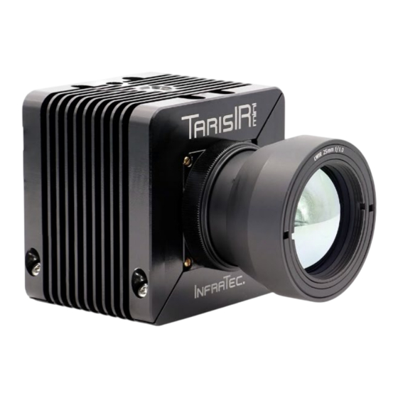
TarisIR® mini
Compact camera
© InfraTec 09/2024 (All the stated product names and trademarks remain in property of their respective owners.)
InfraTec GmbH
Infrarotsensorik und Messtechnik
Gostritzer Straße 61 – 63
01217 Dresden / GERMANY
Phone
+49 351 82876-678
Fax
+49 351 82876-543
E-mail
thermo@InfraTec.de
www.InfraTec.eu
Version: September 2024, I
InfraTec infrared LLC
Phone
5048 Tennyson Pkwy.
E-mail
Plano TX 75024 / USA
+1 844-226-3722 (toll free)
thermo@InfraTec-infrared.com
www.InfraTec-infrared.com
Advertisement
Table of Contents

Related Manuals for InfraTec TarisIR mini


Summary of Contents for InfraTec TarisIR mini
- Page 1 User Manual TarisIR® mini Compact camera Version: September 2024, I © InfraTec 09/2024 (All the stated product names and trademarks remain in property of their respective owners.) InfraTec GmbH Phone +49 351 82876-678 InfraTec infrared LLC Phone +1 844-226-3722 (toll free) Infrarotsensorik und Messtechnik 5048 Tennyson Pkwy.
-
Page 2: Table Of Contents
GigE Interface ..........................15 Installation Instructions ........................... 15 Installing WinPcap ............................ 15 ConFiguring the Network Adapter ......................16 7.3.1 Setting the IP Address ..........................16 Connection With IRBIS® 3* Software ....................18 Environmental Protection ....................... 21 Service ............................22 © InfraTec GmbH 2024... -
Page 3: Introduction
Note Without the written consent of InfraTec GmbH, no part of this user manual must be reproduced or edited, copied or distributed using electronic systems in any form (print, copy, microfilm or any other procedure). Dieses Benutzerhandbuch wurde mit der gebotenen Sorgfalt erarbeitet. This user manual was developed applying due diligence. -
Page 4: Product Specifications
(-40 … 85) °C, (-40 … 55) °C Humidity (operation and storage) Relative humidity (10 … 95) %, not condensing Housing, Protection degree Light metal housing, IP40 Dimensions (50 × 55 × 55) mm Weight (without lens) 220 g © InfraTec GmbH 2024... -
Page 5: Standard Lenses
Further focal lengths are available on request. Lenses are not removeable. Dimensions Figure 2: TarisIR® mini lens independent dimensions Figure 3: TarisIR® mini with 13.6 mm, 6.2 mm and 25 mm lens (minimal length depends on focus setting) © InfraTec GmbH 2024... -
Page 6: Technical Description
5 6-pin system connector (Hirose) 3 Metal housing Scope of Delivery Component image Designation TarisIR® mini camera Including lens Focus adjustment ring (Not necessary for every lens, see “Adjusting the focus”) RJ45 Ethernet cable Standard length: 3m, others on request © InfraTec GmbH 2024... - Page 7 Control interface: D-Sub 9 socket with standard UART/RS232 pinout I/O ports: 2x BNC sockets Power over Ethernet (PoE) Configuration (optional) This powering option consists of an Ethernet cable and a power injector. This option replaces the regular power supply. © InfraTec GmbH 2024...
-
Page 8: Specifics Of Tarisir® Mini - M Version
The housing of the TarisIR® mini M features 4 threaded holes M2, 2.5 mm deep (indicated as “2” in figure 21) 4 on the bottom side 4 on the side For mounting at least two holes are to be used at each side. © InfraTec GmbH 2024... -
Page 9: Operation
Direct adjustment on the focus ring without any tools (with the 25mm lens). Adjustment on the focus ring by using the tool focus adjustment ring (on most lenses). Please note the following images for a better overview of the individual components. © InfraTec GmbH 2024... - Page 10 Insert the focus adjustment ring into the 4 pitches of the focus ring and rotate the focus ring to the required focus position. Clockwise: increase distance to focus position Counterclockwise: decrease distance to focus position Turn the lock ring clockwise to lock the lens position. © InfraTec GmbH 2024...
-
Page 11: Camera Hardware Interfaces
2 I/O ports (3.3 LVTTL) The optional break-out box (see section 3.2) may be needed for interconnection. 6-pin system Hirose connector RJ45 ethernet jack Screw holes for Ethernet cable Camera body Figure 8: Camera rear side © InfraTec GmbH 2024... -
Page 12: Operability
To be applied to M version camera core with 25x25mm² housing only Test norm DIN ISO 9022-(3) 2015-8 Stimulation Semi-sinusoidal Load 800 g / 1 ms Number of stocks 1000 in z direction (optical line) Operating mode Unpacked, passive © InfraTec GmbH 2024... -
Page 13: Climatic Test Conditions
See chapter 3 “Product specifications” Duration 16 h Operating mode Unpacked, active NUC interval Constant humid heat Test norm DIN ISO 9022-12-02-1 Temperature + 40°C Humidity 90-95% rel. humidity Duration 96 h Operating mode Unpacked, passive © InfraTec GmbH 2024... -
Page 14: Electromagnetic Compatibility
DIN EN 61326-1 Electrostatic discharge DIN EN 61000-4-2 Electromagnetic RF fields DIN EN 61000-4-3 0.08 – 1 GHz 10 V/m DIN EN 61000-4-3 1.4 – 2.0 GHz 3 V/m DIN EN 61000-4-3 2.0 – 2.7 GHz 1 V/m © InfraTec GmbH 2024... -
Page 15: Gige Interface
WinPcap is needed. The auto start function of WinPcap driver must be selected. After running the file "WinPcap_4_1_3.exe", follow the setup wizard by clicking "Next >". Figure 9: Set WinPcap Autostart The installation finishes by clicking "Finish". © InfraTec GmbH 2024... -
Page 16: Configuring The Network Adapter
By marking the entry "Internet Protocol (TCP/IP)", you can set the IP address of the GigE network card via the defined within the 192.168.2.xxx range except 192.168.2.201 "Properties" button. This IP address can be under the menu item "Use the following IP address" according to your network's specifications. © InfraTec GmbH 2024... - Page 17 Preferably select the value "1.0 Gbps Full Duplex", and if this is not available, select "Auto Negotiation". If your network card supports this option, you could also set the receive and transmit buffer of the network card to the maximum adjustable value. © InfraTec GmbH 2024...
-
Page 18: Connection With Irbis® 3* Software
It is recommended to operate the camera exclusively via the control PC afterwards. To do this, click the "Remote Control" button in the "Camera" menu item to call up the camera-specific remote control: Figure 16: IRBIS® 3 – Open Camera Remote Control Figure 17: Camera remote control © InfraTec GmbH 2024... - Page 19 Frames can be marked for later analysis in the IRBIS® software suite by an external input signal. This low- high slope signal can be input in either of the two I/O ports after having been selected. Figure 20: Input options © InfraTec GmbH 2024...
- Page 20 Figure 21: Output options Detector Sync – at the beginning of the acquisition of the very thermal image Shutter – when starting the shutter process Static 0 – static 0 V Static 1 – static 3.3 V System information © InfraTec GmbH 2024...
-
Page 21: Environmental Protection
The manufacturer offers to take back the TarisIR® mini product after the end of its usage to ensure environmentally friendly disposal. Please send the device to the address listed in Chapter 10 Service. © InfraTec GmbH 2024... -
Page 22: Service
In case of malfunctions and to perform technical maintenance, please contact your dealer or customer service at the following address: InfraTec GmbH Infrarotsensorik und Messtechnik Gostritzer Straße 61 - 63 01217 Dresden GERMANY Phone: +49 351 82876-678 Fax: +49 351 82876-543 Email: service@InfraTec.de Website: www.InfraTec.de © InfraTec GmbH 2024...
Need help?
Do you have a question about the TarisIR mini and is the answer not in the manual?
Questions and answers