Table of Contents
Advertisement
Quick Links
User Manual
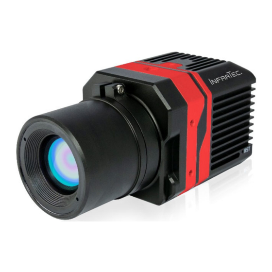
PIR uc 605
Infrared Camera Module
© InfraTec 09/2020 (All the stated product names and trademarks remain in property of their respective owners.)
InfraTec GmbH
Infrarotsensorik und Messtechnik
Gostritzer Straße 61 – 63
01217 Dresden / GERMANY
Phone
+49 351 82876‐610
Fax
+49 351 82876‐543
E‐mail
thermo@InfraTec.de
www.InfraTec.eu
InfraTec infrared LLC
Phone
5048 Tennyson Pkwy.
E‐mail
Plano TX 75024 / USA
State: September 2020
+1 844‐226‐3722 (toll free)
thermo@InfraTec‐infrared.com
www.InfraTec‐infrared.com
Advertisement
Table of Contents

Related Manuals for InfraTec PIR uc 605


Summary of Contents for InfraTec PIR uc 605
- Page 1 User Manual PIR uc 605 Infrared Camera Module State: September 2020 © InfraTec 09/2020 (All the stated product names and trademarks remain in property of their respective owners.) InfraTec GmbH InfraTec infrared LLC Phone +1 844‐226‐3722 (toll free) Phone +49 351 82876‐610 Infrarotsensorik und Messtechnik Fax +49 351 82876‐543 5048 Tennyson Pkwy. E‐mail thermo@InfraTec‐infrared.com Gostritzer Straße 61 – 63 E‐mail thermo@InfraTec.de Plano TX 75024 / USA www.InfraTec‐infrared.com 01217 Dresden / GERMANY ...
-
Page 3: Table Of Contents
Introduction ............................ 3 Notes on Securing the Device ...................... 4 Technical Specificatios ........................ 5 Dimensions ............................ 6 Unpacking and Inspection ........................ 7 Designation of the Camera Parts ...................... 8 Focus Adjustment of the PIR uc 605/20 lens .................... 8 Quick Start ............................ 10 Preparation .............................. 10 Camera Setup ............................ 10 Network Adapter Setting ........................... 10 Setting the IP Address .......................... 11 Connecting the PIR uc 605 with IRBIS® 3.1* .................... 11 Maintenance ............................ 15 Cleaning of Lenses and Protective Windows ..................... 15 Environmental Protection ........................ 16 Service ............................. 17 © InfraTec GmbH 2020 1 ... -
Page 5: Introduction
InfraTec GmbH Infrarotsensorik und Messtechnik Gostritzer Straße 61 – 63 01217 Dresden / GERMANY Phone: +49 351 82876‐610 Fax: +49 351 82876‐543 E‐mail: service@InfraTec.de Internet: www.InfraTec.de Note Without the written consent of InfraTec GmbH, no part of this user manual must be reproduced or edited, copied or distributed using electronic systems in any form (print, copy, microfilm or any other procedure). This user manual was developed applying due diligence. No liability shall be assumed for any damages caused by the non‐observance of the information contained in this user manual. All mentioned product names and trademarks shall remain the property of their respective owners. ... -
Page 6: Notes On Securing The Device
Furthermore, it is essential to prevent the sun or other high‐energy radiation sources from entering the field of view of PIR uc 605 indirectly via reflecting surfaces! When not in use, always attach the lens cap supplied with the PIR uc 605. Do not remove the lenses in rooms with high dust exposure or humidity, as the specified degree of protection cannot be guaranteed when the lens is removed. © InfraTec GmbH 2020 ... -
Page 7: Technical Specificatios
Operating temperature (‐20 … 60) °C Degree of protection IP40 Dimensions (55,8 × 44 × 46) mm (without lens) Weight < 110 g (without lens) Protective housing Robust metal housing Evaluation and analysis software* IRBIS® 3.1 plus*, IRBIS® 3.1 professional*, IRBIS® 3.1 online*, SDK V4* (LabVIEW*, MATLAB*) ** Temperature resolution differs Lenses Focal length (mm) FOV (°) IFOV (mrad) Super wide angle lens 5 (95 × 78) 3,40 Wide angle 10 (59 × 46) 1,77 Normal lens 20 (32 × 24) 0,89 Telephoto Lens 50 (12 × 9) 0,34 © InfraTec GmbH 2020 5 ... -
Page 8: Dimensions
4 Dimensions Dimensions 100 BaseT Interface Power supply, DC 12 V I/O or trigger interface Fig. 1 Housing dimensions of the PIR uc 605 © InfraTec GmbH 2020 ... -
Page 9: Unpacking And Inspection
1 2 7 3 6 8 4 5 Fig. 2 Case contents unpacked (depending on equipment) Components included in the basic package 1 IR camera module PIR uc 605 with lens 2 Lens cover 3 Power supply unit DC 12 V 4 Adapter for camera power supply unit 5 Plug for I/O or trigger interface* 6 Mounting plug for power supply 7 3‐legged table tripod 8 1 m Ethernet cable with RJ45 plug 9 Transport case / Transport packaging Optional equipment* Thermography software of the IRBIS® family © InfraTec GmbH 2020 7 ... -
Page 10: Designation Of The Camera Parts
6 Designation of the Camera Parts Designation of the Camera Parts Power suppy, DC 12 V I/O or trigger interface* 100 BaseT interface Fig. 3 View of rear side Housing (IP40) Lens Fig. 4 Lens side and side view Focus Adjustment of the PIR uc 605/20 lens 2 1 1 The locking ring is used to fix the focus setting 2 Focusing of the lens is carried out by turning the lens (left/right) © InfraTec GmbH 2020 ... - Page 11 6 Designation of the Camera Parts First loosen the grub screw (n) with a 1.3 mm hexagon socket screw driver. To focus the lens, turn the lens (left/right). Thereafter, you can easily tighten the grub screw to lock the lens. The lens may only be focused after the grub screws have been loosened. Otherwise the thread of the lens will be irreparably damaged. © InfraTec GmbH 2020 9 ...
-
Page 12: Quick Start
Establish the Ethernet connection with the computer: Plug the Ethernet cable with the RJ45 connector into the network port of the camera and control computer. System initialisation can be recognised by the camera‐internal shutter noise and the flashing LED on the Ethernet port. The system is ready for operation and can be connected to the software. To turn off the camera, unplug the AC adapter from the wall outlet. No further steps are required. Network Adapter Setting After opening the "Network and Sharing Centre", select the menu item "Change adapter settings". For this purpose the used network card must be marked and its properties must be called up by clicking with the right mouse button. Fig. 5 Selection of LAN connection Administrator rights are required to configure the network card. © InfraTec GmbH 2020 ... -
Page 13: Setting The Ip Address
Before configuring the network card for camera use, check the properties of the interface card to be used. It is important to discharge unnecessary functionalities and to assign a fixed IP address. The screenshots shown here provide an overview: Fig. 6 Properties of LAN connection Fig. 6 Properties of LAN connection When "Internet Protocol (TCP/IP)" is highlighted, the IP address of the network card can be set with the "Properties" button. Define a fixed IP address for your network under the menu item "Use the following IP address", for example 192.168.2.100/255.255.2550. The camera is generally delivered with the following IP address: 192.168.2.128/255.255.255.0 Connecting the PIR uc 605 with IRBIS® 3.1* For correct use of the IRBIS® 3.1 software, please read the supplied IRBIS® 3.1 (digital) manual. Start the IRBIS® 3.1 software. After starting, select the "Connect" function in the "Camera" menu. The menu "Camera" is used to establish the connection. In the selection menu "Select camera", select the camera type "PIR uc 605". Confirm the selection with "Apply". The connection to the camera is then established. Fig. 6 Selection of camera type © InfraTec GmbH 2020 11 ... - Page 14 7 Quick Start After the connection is established, a live image from the camera will be displayed (live button in the camera menu is active). The live image display can be activated or deactivated by pressing the "Live" button. The display of the thermal image can be adjusted or optimised using the corresponding tools of IRBIS® 3.1 (selection of the appropriate temperature scale and a suitable colour palette). Fig. 7 Menu "Camera" to establish camera connection Fig. 8 GUI: Screen example after successful connection Fig. 9 Configuration of remote control parameters The Remote Control selection bar provides access to the settings in the Calibration, Window mode, NUC function and Other buttons. The desired calibration range, (‐20 ... 135) °C or (0 ... 400) °C, can be selected with the "Calibration" (Calib) button. Regardless of the selected calibration range, a frame rate of up to 25 Hz can be selected or entered. © InfraTec GmbH 2020 ...
- Page 15 7 Quick Start Fig. 10 Selection of desired calibration range By using the "Window" button, it is possible to flip the displayed image horizontally or vertically. Fig. 11 Configuration of the window mode The NUC (Non Uniformity Correction) function can be used to correct inhomogeneity within the image. For the PIR u 605 camera model, 1‐point adjustment is available, which corrects the offset values of all pixels. Fig. 12 Activation of "NUC" function The " Miscellaneous " (Misc) button can be used to retrieve service information (for example, camera serial number and version). © InfraTec GmbH 2020 13 ...
- Page 16 7 Quick Start Fig. 13 Service information in the "Miscellaneous" menu © InfraTec GmbH 2020 ...
-
Page 17: Maintenance
8 Maintenance Maintenance Cleaning of Lenses and Protective Windows Surfaces of lenses and protective windows are sensitive to scratches. Improper cleaning can cause damage. Lenses should generally be treated in such a way that cleaning is not necessary. Avoid soiling by wearing protective gloves, preferably made of cotton, when handling the lenses. Avoid cleaning the lenses and protective windows when not necessary. If cleaning is unavoidable, do not clean the surfaces more than necessary. When cleaning, first remove dust and loose particles by blowing with filtered oil‐free compressed air (for example bellows or compressed air can) or with a camel hair brush. For easy cleaning of adhering particles, please use only a clean, fibre and lint‐free cloth (unused optical cleaning cloth or microfibre cloth, wood‐free cellulose). If necessary, add a drop of cleaning solution (see below) in the middle of the cloth. Move the cloth slowly and without pressure over the lens surface. If both the cloth and the surface of the optic are almost dry after wiping, no marks or stains will remain. In the case of heavily adhering contamination or fingerprints, it may be necessary to clean with gentle pressure. In addition to the above‐mentioned cleaning cloths or wood‐free cellulose, surgical cotton swabs or cotton buds are also suitable for this purpose. These can be moistened with several drops of cleaning solution. Before wiping, excess solution should be shaken off by swivelling the wipes, swabs or cotton buds. Wipe very slowly and in one direction only. Scratches will occur if you wipe back and forth quickly. Use a new cleaning cloth, swab or stick for each new wipe. Only ethanol or methanol are suitable as cleaning solutions. © InfraTec GmbH 2020 15 ... -
Page 18: Environmental Protection
9 Environmental Protection Environmental Protection The PIR uc 605 is an optoelectronic device containing special infrared lenses and electronic circuit boards. These components require special disposal after use. The manufacturer offers to take back the product PIR uc 605 from the customer to ensure an environmentally friendly disposal after the end of the use of the device. Please send the machine to the address listed in chapter 10 Service – page 17 if this is the case. © InfraTec GmbH 2020 ... -
Page 19: Service
10 Service Service In the event of malfunctions and to carry out technical maintenance, please contact your dealer or the customer service department at the following address: InfraTec GmbH Infrarotsensorik und Messtechnik Gostritzer Straße 61 – 63 01217 Dresden GERMANY Phone: +49 351 82876‐678 Fax: +49 351 82876‐543 Email: service@InfraTec.eu Internet: www.InfraTec.eu © InfraTec GmbH 2020 17 ...
Need help?
Do you have a question about the PIR uc 605 and is the answer not in the manual?
Questions and answers