
Subscribe to Our Youtube Channel
Related Manuals for Master Image MI-WAVE3D


Summary of Contents for Master Image MI-WAVE3D
- Page 1 Installation & Operation Manual | MI-WAVE3D MI-WAVE3D Digital 3D Cinema System Installation & Operation Manual Revision No. 2.0...
- Page 2 Installation & Operation Manual | MI-WAVE3D Revision History Date Revision Release Status Author Remarks Preliminary PD 0.9 Document June 5, 2012 Preliminary PD 1.0 Document June 7, 2012 Preliminary PD 1.1 Document June 8, 2012 Preliminary PD 1.2 Document June 8, 2012 Preliminary PD 1.3...
- Page 3 Installation & Operation Manual | MI-WAVE3D Locations MASTERIMAGE 3D, INC 5358 Melrose Ave., 4 Floor Hollywood CA 90038 TEL: (323) 606-7800 FAX: (323) 960-8008 MASTERIMAGE 3D ASIA, LLC. 22F, BYC HIGHCITY B/D A, 371-17, Gasan-dong, Geumcheon-gu, Seoul 153-803, South Korea TEL.: +82-2-3438-1600...
-
Page 4: Table Of Contents
The Next Wave in Digital 3D Projection ................. 8 Installation and Configuration ................. 9 4.1. Unpacking the MI-WAVE3D ..................9 4.2. Confirm Package Contents of MI-WAVE3D ..............10 Detailed Component Overview ................11 5.1. Liquid Crystal Polarization Modulator (LCPM) ............. 11 5.2. - Page 5 9.2.9. Factory Setting ....................33 9.2.10. System Information .................... 34 Appendix A – Firmware Upgrade Process for MI-WAVE3D ......... 35 10.1. Prerequisites for Upgrading Firmware ................. 35 10.2. Upgrade Firmware ...................... 35 10.3. Check the STM Virtual COM Port Number ..............38 Appendix B –...
-
Page 6: Introduction
3D picture of any available liquid crystal 3D system. This user manual provides all the information required for simple installations and the operation of the MI-WAVE3D, with any DLP cinema projector and digital cinema server. 1.2. -
Page 7: Warnings And Cautions
2. Warnings and Cautions 2.1. Installation Consideration When planning installation of the MI-WAVE3D, ensure that the largest image possible is projected onto the liquid crystal polarization modulator (LCPM). The image width should be between 155mm and 165mm and centered on the LCPM, as shown below. -
Page 8: System Overview
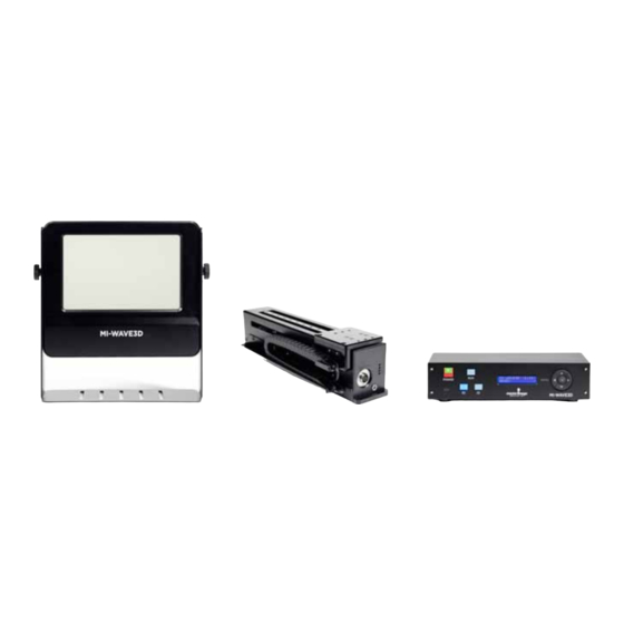
MI-WAVE3D provides an accurate synchronization function for both current format 72Hz, 24fps, triple flash and future HFR 3D formats. MI-WAVE3D is perfectly matched to the high quality polarized 3D eyewear produced by MASTERIMAGE 3D. MI-WAVE3D consists of Liquid Crystal Polarization Modulator, Actuator and Control Box, connection cables, and mounting frame. -
Page 9: Installation And Configuration
Installation & Operation Manual | MI-WAVE3D 4. Installation and Configuration 4.1. Unpacking the MI-WAVE3D Inspect the MI-WAVE3D packaging box for any external damage. Report any damage to shipper and to MasterImage 3D. Top layer package contains 4 cartons Cables, power adapter, and 3D glasses... -
Page 10: Confirm Package Contents Of Mi-Wave3D
Installation & Operation Manual | MI-WAVE3D 4.2. Confirm Package Contents of MI-WAVE3D Liquid Crystal Polarization Modulator (LCPM) Actuator Control Box and Rack Mount Accessory Power Adaptor Sync Cable Actuator Cable Mounting Frames ... -
Page 11: Detailed Component Overview
Installation & Operation Manual | MI-WAVE3D 5. Detailed Component Overview 5.1. Liquid Crystal Polarization Modulator (LCPM) LC Panel LC Panel Frame Cooling Fan Stand is used to adjust the height and angle of the LC Frame with respect to the... -
Page 12: Actuator
Installation & Operation Manual | MI-WAVE3D 5.2. Actuator LCPM Cable Connector Mounting Plate for LCPM Actuator Cable Connector Indicator LED Robot Chain LCPM Installed on the Actuator © MASTERIMAGE 3D, Inc. -
Page 13: Control Box - Front Panel
Installation & Operation Manual | MI-WAVE3D Control Box – Front Panel 5.3. Operation LCD: Mini USB: Displays Firmware version Power Button Used to upgrade and Current Firmware or Operating State connect Monitor Run/Stop Button Program Reset Button 3D Button: Setup Keys... -
Page 14: Control Box - Rack Mount
Installation & Operation Manual | MI-WAVE3D Control Box – Rack Mount 5.5. 6. System Setup 6.1. Installation Options Before choosing the best method for mounting the actuator in front of the projector, manually hold the LCPM in front of the projection lens so that an image width of between 155mm and 165mm is visible on the LC panel. -
Page 15: Projector Lens Consideration
Installation & Operation Manual | MI-WAVE3D Figure 2. Port Wall Installation Figure 3. Projector Pedestal Installation 6.2. Projector Lens Consideration You can orient the actuator mounting frame in two directions depending on the amount of lens extension from the front of the projector. -
Page 16: Initial Actuator/Lcpm Assembly
Installation & Operation Manual | MI-WAVE3D Figure 4. Short Lens Figure 5. Long Lens 6.3. Initial Actuator/LCPM Assembly 6.3.1. Attach Actuator to Horizontal Frame Rail With the actuator upside-down, attach it to the horizontal mounting frame rail with the 4 supplied screws (Figure 6). - Page 17 Installation & Operation Manual | MI-WAVE3D Connect the LCPM cable from the robot chain to the connector on the underside of the LCPM (Figure 8). Figure 8. LCPM Cable Connection LCPM Height & Angle Adjustment When installing the assembly in front of...
-
Page 18: Control Box Cable Connections
Installation & Operation Manual | MI-WAVE3D The LCPM must be adjusted so that it is perpendicular to the light path exiting the lens. Figure 10. Adjust LCPM Tilt Perpendicular to Light Path 6.4. Control Box Cable Connections Prior to making control box cable connections, mount the control box into the equipment rack (if desired) using the rack mount accessory. -
Page 19: Actuator Connector
Installation & Operation Manual | MI-WAVE3D 6.4.2. Actuator Connector Connect the actuator cable to both the actuator and control box (Figure 12). Figure 12. Actuator Cable Connections 6.4.3. GPIO Cable Connect the GPIO cable from the DLP Digital Cinema Projector (Figure 13). -
Page 20: Initial Test
Installation & Operation Manual | MI-WAVE3D 6.5. Initial Test 6.5.1. Auto Power On To turn on the control box power automatically, connect the main cable from the DC power to a power outlet. The LCD display panel indicates the model name, current system firmware version, and that it is in a READY state (Figure 15). -
Page 21: Basic System Operation
Installation & Operation Manual | MI-WAVE3D 7. Basic System Operation System Ready – Standby 7.1. Condition Figure 17 To turn on the system power, press the POWER button for 1 second and release it. The LCD on the Power button should be on and the LCD display indicates the READY condition (Figure 17). -
Page 22: System Power Off
8.1. Projector 3D File Configuration The projector’s 3D control file must be configured to work with the MI-WAVE3D. These procedures describe configuring the control files for Series II projectors. The Dark Time should be set to 350µS with the Delay being left at 0µS. These figures are applicable to all frame rates and projector flash configurations. -
Page 23: Christie Series Ii File Settings For External Server Playback
Installation & Operation Manual | MI-WAVE3D 8.2.2. Christie Series II File Settings for External Server Playback Figure 24 8.2.3. Barco Series II File Settings for External Server Playback Figure 25 © MASTERIMAGE 3D, Inc. -
Page 24: Imb Configuration Settings
Installation & Operation Manual | MI-WAVE3D Note: Barco Series II projectors have a pre-installed 3D configuration file for the settings required by the MI-CLARITY3D system. It is possible to select this file rather than making fully manual entries, but editing of Dark Time and Output Reference Delay would be required 8.2.4. -
Page 25: Mi-Wave3D Detailed Operation
Installation & Operation Manual | MI-WAVE3D 9. MI-WAVE3D Detailed Operation 9.1. MI-WAVE3D Menu Tree Level Level Level Level >1 3D PHASE TRUE >1 1. SYNcPOLARITY INVERT >2 2.OFFSET [CANCEL] [SAVE] 3. EXIT >2 OFFSET OLD: mmm NEW: [MMM] [SAVE][CANCEL] Adjust sync polarity and the offset of 3D phase if any 3D artifacts are seen on screen... - Page 26 Installation & Operation Manual | MI-WAVE3D >1 >1 1.PASSWORD [OFF]* SET PASSWORD PASSWORD >2 2.NEW PASSWORD 3.EXIT [SAVE][CANCEL] >2 >3 NEW PASSWORD CONFIRM PASSWORD KEY: [o] KEY: [o] * * * * * * * * [SAVE][CANCEL] [SAVE][CANCEL] Turn on or off system password, set new 4-digit password...
-
Page 27: Explanation Of Menu Items
Installation & Operation Manual | MI-WAVE3D 9.2. Explanation of Menu Items To access menu items on the front of the control box, press the MENU button for 1 second and release it. The SETUP menu appears. 9.2.1. 3D Phase – Sync Polarity If the 3D sync polarity of the image becomes inverted, it can be corrected in this menu item. -
Page 28: Phase - Offset
Installation & Operation Manual | MI-WAVE3D 9.2.2. 3D Phase – Offset If the 3D image is slightly unsynchronized it can be adjusted in the menu item. Using the control arrow keys follow the sequence (below) to invert the 3D Phase Offset setting. -
Page 29: Automation Source
Installation & Operation Manual | MI-WAVE3D 9.2.4. Automation Source The system can be automated via several different sources. This menu item allows the source in use to be selected. The options are: Manual – Control via front panel button ... -
Page 30: Fan Speed
Installation & Operation Manual | MI-WAVE3D Sync Pulse Option Selection Save the new setting. 9.2.6. Fan Speed The cooling fan speed on the LCPM can be set to Low, Mid, or Max. The default is Max. Using the control arrow keys, follow the sequence (below) to switch the Fan Speed setting. -
Page 31: Menu Password Option
Installation & Operation Manual | MI-WAVE3D 9.2.7. Menu Password Option You can password protect the setup menu functions of the MI-WAVE3D. The default password is 0000. Using the control arrow keys, follow the sequence (below) to switch the Menu Password function on or off as required. -
Page 32: Ethernet Configuration
Installation & Operation Manual | MI-WAVE3D 9.2.8. Ethernet Configuration If you want to automate the operation of the MI-WAVE3D via digital cinema server command protocols you must configure the Ethernet settings of the system to match your internal network. The configurable settings are: ... -
Page 33: Factory Setting
Save the new setting. 9.2.9. Factory Setting From time to time, you may need to reset the MI-WAVE3D to the factory configuration. Using the control arrow keys follow the sequence (below) to set the factory default settings of the system. Press the OK button to select and confirm selections. -
Page 34: System Information
Installation & Operation Manual | MI-WAVE3D 9.2.10. System Information You can see the firmware version and date the system was upgraded on this menu item. Using the control arrow keys follow the sequence (below) to see the information for the system. -
Page 35: Appendix A - Firmware Upgrade Process For Mi-Wave3D
Upgrade Firmware 1. Connect the MI-WAVE3D control box AC power adaptor and wait for the power-on screen to be in the READY state. 2. Connect the MI-WAVE3D control box to your PC with the USB cable. © MASTERIMAGE 3D, Inc. - Page 36 Installation & Operation Manual | MI-WAVE3D 3. Execute “MIDfu” utility by double- clicking the utility’s icon on your PC. 4. Click the Setup button to open the Serial Setting window. 5. Select the COM port assigned by the “STMicroelectronics Virtual COM Port Driver”.
- Page 37 Installation & Operation Manual | MI-WAVE3D 8. Select the latest firmware file having a “*.bin” file extension, then click the Open button to load the file into the upgrade utility. 9. Click the Upgrade button to start firmware upgrading. During the process, the LCD screens shown below will display:42 10.
-
Page 38: Check The Stm Virtual Com Port Number
10.3. Check the STM Virtual COM Port Number You can verify the virtual COM Port number after connecting MI-WAVE3D to your 1. Run the Control Panel in your PC. 2. Open the Device Manager within the Hardware and Sound option. -
Page 39: Appendix B - Mi-Wave3D Automation
Installation & Operation Manual | MI-WAVE3D 11. Appendix B – MI-WAVE3D Automation Table B-1. GPIO Automation DSUB9(GPIO) Comm. DSUB37 Direc- Pin name Description Comments tion number number No connection PRJ_COM_nRUN 12(+) LCPM RUN command Comparator 24V max, 31(-) 12V threshold ... - Page 40 Installation & Operation Manual | MI-WAVE3D Table B-2. RS232 Automation DSUB9(RS-232) Comm. DSUB9 Direc- Description Comments Pin name tion number number No connection Transmitter RS-232 Driver (ST3232ECTR) Receiver (Max :±25V) No connection Ground Inverting receiver RS-485/422 RXDM Driver (Max :±25V)
-
Page 41: Ethernet Automation
3. Select the Raw option to create MasterImage as a known device in the server’s listing. 4. Complete the fields as shown below. Ensure the settings entered match those of the MI-WAVE3D for IP Address and Port Number. Check the Enabled box and save the entry. - Page 42 Installation & Operation Manual | MI-WAVE3D The MI-WAVE3D has now been successfully added into the server configuration. It is now possible to create the macro files to enable the server to control the MI-WAVE3D. The files required are: MasterImage Start, MasterImage Stop, MasterImage 2D, MasterImage 3D and MasterImage Up/Down Stop.
- Page 43 Installation & Operation Manual | MI-WAVE3D 2. After the item has been created click OK return to the main Macro Editor screen. Repeat this process for the other four required macros, MasterImage Stop, MasterImage 2D, MasterImage 3D and MasterImage Up/Down Stop.
- Page 44 Installation & Operation Manual | MI-WAVE3D 4. Highlight the Input/Output option and Send Message, and then click the Add button. The following configuration window will appear: 5. In this window, choose the device MasterImage from the Device name dropdown list and type in the Message label of MasterImage Start. Ensure the Message type is Text and type Start\n in the Message box.
- Page 45 Installation & Operation Manual | MI-WAVE3D In future versions of Doremi software updates, the MasterImage macros will be included in a file named MasterImage_cueslib. This will remove the requirement for the information to be entered manually as described in the above steps.
-
Page 46: Qube Server
Installation & Operation Manual | MI-WAVE3D 11.1.2. Qube Server To create automation macros for the MI-WAVE3D in the Qube server it is necessary to edit two XML files within the server’s configuration. The files in question are located in the path C:/Program Files/Qube Cinema/XP and are named automationdevices.xml and automationcues.xml... - Page 47 Installation & Operation Manual | MI-WAVE3D 2. Complete the fields with the details of the MasterImage MI-CLARITY3D where: “Device “MasterImage” Name” “Device “Qube.Automation.streamdevice.TCP” Class” “file name of the “MasterImage.xml” device” “addess value” MI-WAVE3D Assigned IP Address “port “23” value” It is recommended that Notepad++ or a similar program is used for xml file editing.
- Page 48 Finally the automationcues.xml file can be edited so that the MI-WAVE3D device is associated with the command names that have been created. This allows the cues to be seen in the Qube graphical interface.
-
Page 49: Gdc Server
Installation & Operation Manual | MI-WAVE3D Once this file has been edited and saved the graphical interface of the Qube server will display the new cues that can be selected for future playlist creation. 11.1.3. GDC Server The steps described below are specific to the GDC SX-2001 server. If information is required for different models, please contact GDC directly. - Page 50 2. Once you have logged on, click the Automation button found on the General tab. The MI-WAVE3D must be added as a device within the GDC server configuration. 3. Select the Devices tab and click the Add button. © MASTERIMAGE 3D, Inc.
- Page 51 4. Name the new device MasterImage, and ensure the Type selection is set to NETWORKSOCKET, then click OK. 5. In the next screen, enter the configuration settings for the MI-WAVE3D IP Address and Port Number. 6. In the Transport option select TCP and in the Linefeed Type select CR and ensure the Status is set to Enabled.
- Page 52 Installation & Operation Manual | MI-WAVE3D Last, it is necessary to program the control macros in the server. 8. Click the Edit Control Cues button and the following screen will display. 9. Click the Add button to create a new event. In this case, name the event START.
- Page 53 Installation & Operation Manual | MI-WAVE3D 10. Click the Enter button and enter the command value for the event. Again in this case, START. 11. Click the Enter button to save this change, then go back and make entries for the remaining four macros that are required.
- Page 54 Installation & Operation Manual | MI-WAVE3D 12. Once all macros have been created, return to the Actions tab of the Automation screen to create the events that are needed to communicate. This is done by clicking the Add button. 13. For each event, choose the device that was defined in the first step, MasterImage, and then select the required event action from the dropdown list, for example: Start.
-
Page 55: Appendix C - Installation Record
Installation & Operation Manual | MI-WAVE3D 12. Appendix C – Installation Record The form below is an example of the installation record form to be filled out once the MI- WAVE3D has been set up and configured. For a copy of the form to be filled out, ‘contact your equipment provider or email a request to support@masterimage3d.com. -
Page 56: Appendix D - Dimensional Drawings
Installation & Operation Manual | MI-WAVE3D 13. Appendix D – Dimensional Drawings Liquid Crystal Polarization Modulator (LCPM) © MASTERIMAGE 3D, Inc. - Page 57 Installation & Operation Manual | MI-WAVE3D Control Box © MASTERIMAGE 3D, Inc.
- Page 58 Installation & Operation Manual | MI-WAVE3D Actuator © MASTERIMAGE 3D, Inc.
- Page 59 Installation & Operation Manual | MI-WAVE3D Mounting Frame Assembly for Short Projector Lens © MASTERIMAGE 3D, Inc.
- Page 60 Installation & Operation Manual | MI-WAVE3D Mounting Frame Assembly for Long Projector Lens © MASTERIMAGE 3D, Inc.
- Page 61 Installation & Operation Manual | MI-WAVE3D Installation Example Using Mounting Frame Assembly for Long Projector Lens End of Manual For additional information, go to www.masterimage3d.com. © MASTERIMAGE 3D, Inc.
- Page 62 Installation & Operation Manual | MI-WAVE3D © MASTERIMAGE 3D, Inc.
Need help?
Do you have a question about the MI-WAVE3D and is the answer not in the manual?
Questions and answers