
Related Manuals for Master Image MI-WAVE3D


Summary of Contents for Master Image MI-WAVE3D
- Page 1 Installation & Operation Manual | MI-WAVE3D MI-WAVE3D Digital 3D Cinema System Installation & Operation Manual Revision No. 1.0.1...
- Page 2 Installation & Operation Manual | MI-WAVE3D Revision History Date Revision Release Status Author Remarks December 19 Preliminary PD 1.0 2013 Document February 25 Preliminary PD 1.1 2014 Document February 27 Preliminary PD 1.2 Firmware Utility Changes 2014 Document May 21 2014 1.0.0...
- Page 3 Installation & Operation Manual | MI-WAVE3D Locations MASTERIMAGE 3D, INC 15260 Ventura Blvd, Suite 1220, Sherman Oaks, CA 91403 USA TEL: (323) 606-7800 FAX: (323) 301-7985 MASTERIMAGE 3D ASIA, LLC. 22F, BYC HIGHCITY B/D A, 371-17, Gasan-dong, Geumcheon-gu, Seoul 153-803, South Korea TEL.: +82-2-3438-1600...
-
Page 4: Table Of Contents
The Next Wave in Digital 3D Projection ................. 9 Installation and Configuration ................10 4.1. Unpacking the MI-WAVE3D ..................10 4.2. Confirm Package Contents of MI-WAVE3D ..............11 Detailed Component Overview ................12 5.1. Liquid Crystal Polarization Modulator (LCPM) ............. 12 5.2. - Page 5 9.3.17. Factory Default via the Monitor Application ............41 MI-WAVE3D Troubleshooting................42 10.1. Error Indication via LED Display .................. 42 Appendix A – Firmware Upgrade Process for MI-WAVE3D ......... 43 11.1. Prerequisites for Upgrading Firmware ................. 43 11.2. Firmware Upgrade Procedure ..................43...
- Page 6 Installation & Operation Manual | MI-WAVE3D Appendix B – MI-WAVE3D Automation ..............47 12.1. Ethernet Automation ....................49 12.1.1. Doremi Server ....................49 12.1.2. Qube Server ...................... 55 12.1.3. GDC Server ....................... 58 Appendix C – Installation Record ................. 64 Appendix D –...
-
Page 7: Introduction
3D picture of any available liquid crystal 3D system. This user manual provides all the information required for simple installations and the operation of the MI-WAVE3D, with any DLP cinema projector and digital cinema server. 1.2. -
Page 8: Warnings And Cautions
2. Warnings and Cautions 2.1. Installation Consideration When planning installation of the MI-WAVE3D, ensure that the largest image possible is projected onto the liquid crystal polarization modulator (LCPM). The image width should be between 155mm and 165mm and centered on the LCPM, as shown below. -
Page 9: System Overview
MI-WAVE3D provides an accurate synchronization function for both current format 72Hz, 24fps, triple flash along with 48fps and 60fps HFR 3D formats. MI-WAVE3D is perfectly matched to the high quality polarized 3D eyewear produced by MASTERIMAGE 3D. MI-WAVE3D consists of Liquid Crystal Polarization Modulator, Actuator and Control Box, connection cables, and mounting frame. -
Page 10: Installation And Configuration
Installation & Operation Manual | MI-WAVE3D 4. Installation and Configuration 4.1. Unpacking the MI-WAVE3D Inspect the MI-WAVE3D packaging box for any external damage. Report any damage to shipper and to MasterImage 3D. Top layer package contains 4 cartons Cables, power adapter, and 3D glasses layer, LCPM, cooling fans &... -
Page 11: Confirm Package Contents Of Mi-Wave3D
Installation & Operation Manual | MI-WAVE3D 4.2. Confirm Package Contents of MI-WAVE3D Liquid Crystal Polarization Modulator (LCPM) Actuator Control Box and Rack Mount Accessory Power Adaptor Sync Cable Actuator Cable Mounting Frames ... -
Page 12: Detailed Component Overview
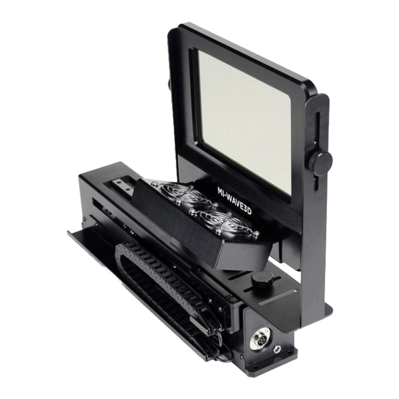
Installation & Operation Manual | MI-WAVE3D 5. Detailed Component Overview 5.1. Liquid Crystal Polarization Modulator (LCPM) LC Frame Liquid Crystal Panel 3-Digit LED RUN/STOP Button Cooling Fan Stand : Used to adjust the height and an gle of the LC Frame in respect to the projector lens. -
Page 13: Actuator
Installation & Operation Manual | MI-WAVE3D 5.2. Actuator Stroke: 300mm Mounting Plate for LC P olarization Modulator Robot Chain Power Adaptor Jack Sync Cable USB Connector (for F/W Download) GPIO Sync Cable Connector DC Power Adaptor Connector Actuator Connector (for Test Jig) -
Page 14: System Setup
Installation & Operation Manual | MI-WAVE3D 6. System Setup 6.1. Installation Options Before choosing the best method for mounting the actuator in front of the projector, manually hold the LCPM in front of the projection lens so that an image width of between 155mm and 165mm is visible on the LC panel. -
Page 15: Projector Lens Consideration
Installation & Operation Manual | MI-WAVE3D Figure 3. Projector Pedestal Installation 6.2. Projector Lens Consideration You can orient the actuator mounting frame in two directions depending on the amount of lens extension from the front of the projector. In general, both NEC and Barco projectors tend to have a shorter lens design than the Christie models. -
Page 16: Initial Actuator/Lcpm Assembly
Installation & Operation Manual | MI-WAVE3D 6.3. Initial Actuator/LCPM Assembly 6.3.1. Attach Cooling Fan Assembly to LCPM Attach the cooling fan assembly to the LCPM Frame with two supplied screws. (Figure 6). Figure 6. Fan Mounting 6.3.2. Attach LCPM Frame to Actuator... -
Page 17: Connect The Actuator Cables
Installation & Operation Manual | MI-WAVE3D 6.3.3. Connect the Actuator Cables Connect the GPIO Sync Cable and DC Adaptor Cable to the end of the Actuator. (Figure 9). Figure 9. Height and Angle Adjustment Screws 6.3.4. Attach the Actuator Mounting Base... -
Page 18: Assemble The Actuator Mounting Unit
Installation & Operation Manual | MI-WAVE3D 6.3.6. Assemble the Actuator Mounting Unit Fix the actuator mounting plate on the actuator mounting base with 6 supplied screws. (Figure 12). Figure 12. Actuator Mounting Unit 6.3.7. Installation Considerations LCPM Height & Angle Adjustment... -
Page 19: Initial Test
Installation & Operation Manual | MI-WAVE3D 6.4. Initial Test 6.4.1. System Power Connect the mains cable from the DC power supply to a power outlet. The LCD display panel in the bottom right corner of the LCPM indicates ‘00’, this shows that the system is in a READY state (Figure 15). -
Page 20: Test Actuator Operation - 2D Position
Installation & Operation Manual | MI-WAVE3D 6.4.3. Test Actuator Operation – 2D Position Press and hold the Actuator 2D button for 1 second and release. The Actuator will transition to the 2D position with the 2D button LED flashing, and the cooling fans will stop. -
Page 21: Basic System Operation
Installation & Operation Manual | MI-WAVE3D 7. Basic System Operation System Ready – Standby Condition 7.1. When the system DC power supply is connected to power the ‘00’ of the LCPM LED display indicates ‘Ready’ status. If the system is already connected to an active GPIO signal the incoming frequency will be displayed. - Page 22 Installation & Operation Manual | MI-WAVE3D If the actuator is in the 3D position when the LCPM operation is stopped the cooling fans will remain operational to protect the LCPM from thermal damage. Press and hold the actuator 2D button for 1 second to transition to 2D position and the cooling fans will stop operation.
-
Page 23: Projector Configuration
8.1. Projector 3D File Configuration The projector’s 3D control file must be configured to work with the MI-WAVE3D. These procedures describe configuring the control files for Series II projectors. The Dark Time should be set to 350µS with the Delay being left at -120µS. These figures are applicable to all frame rates and projector flash configurations. -
Page 24: Christie Series Ii File Settings For External Server Playback
Installation & Operation Manual | MI-WAVE3D 8.2.2. Christie Series II File Settings for External Server Playback Figure 21 8.2.3. Barco Series II File Settings for External Server Playback Figure 22 © MASTERIMAGE 3D, Inc. -
Page 25: Imb Configuration Settings
Installation & Operation Manual | MI-WAVE3D Barco Series II projectors have a pre-installed 3D configuration file for the settings required by the MI-CLARITY3D system. It is possible to select this file rather than making fully manual entries, but editing of Dark Time and Output Reference Delay would be required. -
Page 26: Mi-Wave3D Detailed Setup & Configuration
Installation & Operation Manual | MI-WAVE3D 9. MI-WAVE3D Detailed Setup & Configuration 9.1. 3D Phase Sync Polarity If necessary it is possible to change the sync polarity of the 3D phase by changing the position of Mode Selector switch 2 on the bottom of the LCPM. -
Page 27: System Setup Using The Monitor Application
System Setup Using the Monitor Application 9.3.1. Initial Configuration Connect your PC to the MI-WAVE3D with an Ethernet cable and configure your network settings with Control Panel of Microsoft Windows. You can use a different IP address that is suitable to your network 9.3.2. -
Page 28: Changing The User Password
To prevent access to the MI-WAVE3D from unauthorized persons it is possible to change the system password. Click the [New Password] link in the upper right corner of the MI-WAVE3D Web Server and the ‘Change Password’ dialog box will be displayed. -
Page 29: System Operation Via The Monitor Application
Installation & Operation Manual | MI-WAVE3D • Input the current password. (mi) • Input a new password. Input the new password for confirmation and click the [Save password] • button. 9.3.4. System Operation via the Monitor Application Click the [RUN] button to start the LCPM operation. -
Page 30: Position Movement Via The Monitor Application
Installation & Operation Manual | MI-WAVE3D The indication under Status will change from ‘Ready’ to ‘Running’. The cooling fans will be operational and this will be displayed in the application. Once synchronized the LCPM frequency will be displayed. 9.3.5. Position Movement via the Monitor Application 9.3.6. -
Page 31: Position
Installation & Operation Manual | MI-WAVE3D 9.3.7. 2D Position Click the [2D] button to move the actuator to the 2D position. The color of the [3D] button will change from green to black. The color of the [2D] button will change from black to green. -
Page 32: Sync Polarity Via The Monitor Application
Installation & Operation Manual | MI-WAVE3D 9.3.8. Sync Polarity via the Monitor Application Check the current value of the Sync Polarity. Depending on the condition of 3D material on screen change the Sync Polarity as required from ‘True’ to ‘Invert’. -
Page 33: Setting 3D Position Via The Monitor Application
Installation & Operation Manual | MI-WAVE3D 9.3.9. Setting 3D Position via the Monitor Application Check the current setting for the 3D position of the Actuator. If required by the installation requirements for the system the 3D Position can be changed from ‘Left’... -
Page 34: Sync Pulse Automation Reference Frequency Via The Monitor Application
Installation & Operation Manual | MI-WAVE3D The options available for selection are: Manual – Control via front panel button GPIO (37-9) – Automation via the 37-pin GPIO cable connection GPIO (15-9) – Automation via the 15-pin GPIO cable connection ... -
Page 35: Delay Time Via The Monitor Application
Installation & Operation Manual | MI-WAVE3D 9.3.12. 2D Delay Time via the Monitor Application When using the Sync Pulse Automation option with material of varying frequency or frame rate it may be necessary to apply 2D Delay Time to the system to prevent unwanted 2D transition. -
Page 36: Network Configuration Via The Monitor Application
9.3.13. Network Configuration via the Monitor Application Configure the network settings of the MI-WAVE3D to operate on your network via ethernet communication. Click [Network Configuration] to access the settings window. Enter the IP Address, Gateway, Subnet Mask, Primary DNS and Secondary DNS of your network accordingly. -
Page 37: Fan Speed Via The Monitor Application
Installation & Operation Manual | MI-WAVE3D 9.3.14. Fan Speed via the Monitor Application Check the current setting for the Fan Speed. The default is HIGH. You can reduce the noise of the cooling fans by adjusting the fan speed. The speed can be changed to either [MID] or [LOW] accordingly. -
Page 38: Sync Source Via The Monitor Application
Installation & Operation Manual | MI-WAVE3D 9.3.15. Sync Source via the Monitor Application Check the current setting for the Sync Source. The default is [GPIO]. Choose the option for [TTL] if the system is being used in a non-cinema application. -
Page 39: Log File Via The Monitor Application
Installation & Operation Manual | MI-WAVE3D 9.3.16. Log File via the Monitor Application The system contains a log function that stores the last 200 records of activity including any errors that occurred. In order to access the log file click [Log] at the top of the Monitor Application. - Page 40 Installation & Operation Manual | MI-WAVE3D Description # POWER ON : v1.0.0 Power On : Firmware Version Number RUNNING RUNNING STOP STOP Current Position : 2D 2D MOVING Actuator Moving to 2D Position Current Position : 3D Status 3D MOVING...
-
Page 41: Factory Default Via The Monitor Application
Installation & Operation Manual | MI-WAVE3D 9.3.17. Factory Default via the Monitor Application Should it be necessary for any reason to reset the system to Factory Default this can be achieved by clicking the [Default] button. This can be completed for operational settings or network configuration. -
Page 42: Mi-Wave3D Troubleshooting
Installation & Operation Manual | MI-WAVE3D 10. MI-WAVE3D Troubleshooting. 10.1. Error Indication via LED Display Check the LCPM LED display for any error indication as per the below table. Error code Description No connection with the Actuator No movement of the Actuator normally... -
Page 43: Appendix A - Firmware Upgrade Process For Mi-Wave3D
4. Prepare a CAT5-E cable for connection to the system. 11.2. Firmware Upgrade Procedure 1. Connect the MI-WAVE3D control box to your PC with the Ethernet cable. 2. Execute “MITftp” utility by double- clicking the utility’s icon on your PC. © MASTERIMAGE 3D, Inc. - Page 44 Installation & Operation Manual | MI-WAVE3D Device’s IP Address TFTP Port number 192.168.10.95) (Default: (Default: 69) Hex file name Open Hex file size Hex file Log message Updating progressive bar Upgrade button Exit button 3. Configure the utility to match your individual site network requirements.
- Page 45 Installation & Operation Manual | MI-WAVE3D 4. Click the [Open] button to select the firmware (.hex) file saved to your PC. 5. Select the file to be used and click [Open]. 6. Click the [Upgrade] button to start the upgrade of the selected file to the system.
- Page 46 Installation & Operation Manual | MI-WAVE3D 7. You will see the “Start Firmware Upgrade” message in the utility after pressing the [Upgrade] button. 8. You will see the “Success Firmware Upgrade” message in the utility after the progress bar reaches the end.
-
Page 47: Appendix B - Mi-Wave3D Automation
Installation & Operation Manual | MI-WAVE3D 12. Appendix B – MI-WAVE3D Automation Table B-1. GPIO (37-9 pin) Automation DSUB9(GPIO) Comm. DSUB37 Direc- Pin name Description Comments tion number number No connection PRJ_COM_nRUN 12(+) LCPM RUN command Comparator 24V max,... - Page 48 Installation & Operation Manual | MI-WAVE3D Table B-2. GPIO (15-9 pin) Automation DSUB9(GPIO) DSUB15 Comm. Description Comments Direction Pin name number number Comparator 24V max , ← SYNC 7(+) Vertical sync pulse 12 threshold (LM2901H) 13,14 Ground Shield frame frame...
-
Page 49: Ethernet Automation
3. Select the Raw option to create MasterImage as a known device in the server’s listing. 4. Complete the fields as shown below. Ensure the settings entered match those of the MI-WAVE3D for IP Address and Port Number. Check the Enabled box and save the entry. - Page 50 Installation & Operation Manual | MI-WAVE3D The MI-WAVE3D has now been successfully added into the server configuration. It is now possible to create the macro files to enable the server to control the MI-WAVE3D. The files required are: MasterImage Start, MasterImage Stop, MasterImage 2D, MasterImage 3D and MasterImage Up/Down Stop.
- Page 51 Installation & Operation Manual | MI-WAVE3D 2. After the item has been created click OK return to the main Macro Editor screen. Repeat this process for the other four required macros, MasterImage Stop, MasterImage 2D, MasterImage 3D and MasterImage Up/Down Stop.
- Page 52 Installation & Operation Manual | MI-WAVE3D 4. Highlight the Input/Output option and Send Message, and then click the Add button. The following configuration window will appear: 5. In this window, choose the device MasterImage from the Device name dropdown list and type in the Message label of MasterImage Start. Ensure the Message type is Text and type Start\n in the Message box.
- Page 53 Installation & Operation Manual | MI-WAVE3D In future versions of Doremi software updates, the MasterImage macros will be included in a file named MasterImage_cueslib. This will remove the requirement for the information to be entered manually as described in the above steps.
- Page 54 Installation & Operation Manual | MI-WAVE3D © MASTERIMAGE 3D, Inc.
-
Page 55: Qube Server
Installation & Operation Manual | MI-WAVE3D 12.1.2. Qube Server To create automation macros for the MI-WAVE3D in the Qube server it is necessary to edit two XML files within the server’s configuration. The files in question are located in the path C:/Program Files/Qube Cinema/XP and are named automationdevices.xml and automationcues.xml... - Page 56 Finally the automationcues.xml file can be edited so that the MI-WAVE3D device is associated with the command names that have been created. This allows the cues to be seen in the Qube graphical interface.
- Page 57 Installation & Operation Manual | MI-WAVE3D <Cue name="Start 3D"> <Actions> <InvokeMethod name="Start" device="MasterImage"/> </Actions> </Cue> <Cue name="Stop 3D"> <Actions> <InvokeMethod name="Stop" device="MasterImage"/> </Actions> </Cue> <Cue name="3D Position"> <Actions> <InvokeMethod name="3Dposition" device="MasterImage"/> </Actions> </Cue> <Cue name="2D Position"> <Actions> <InvokeMethod name="2Dposition" device="MasterImage"/>...
-
Page 58: Gdc Server
Installation & Operation Manual | MI-WAVE3D 12.1.3. GDC Server The steps described below are specific to the GDC SX-2001 server. If information is required for different models, please contact GDC directly. 1. In the SMS Main Menu click the Control Panel button and log on as Maintenance Access. - Page 59 Installation & Operation Manual | MI-WAVE3D The MI-WAVE3D must be added as a device within the GDC server configuration. 3. Select the Devices tab and click the Add button. The following screen will display: © MASTERIMAGE 3D, Inc.
- Page 60 4. Name the new device MasterImage, and ensure the Type selection is set to NETWORKSOCKET, then click OK. 5. In the next screen, enter the configuration settings for the MI-WAVE3D IP Address and Port Number. 6. In the Transport option select TCP and in the Linefeed Type select CR and ensure the Status is set to Enabled.
- Page 61 Installation & Operation Manual | MI-WAVE3D 9. Click the Add button to create a new event. In this case, name the event START. 10. Click the Enter button and enter the command value for the event. Again in this case, START.
- Page 62 Installation & Operation Manual | MI-WAVE3D 11. Click the Enter button to save this change, then go back and make entries for the remaining four macros that are required. Event Name STOP Enter Value STOP Event Name 2D POSITION Enter Value PFD DOWN...
- Page 63 Installation & Operation Manual | MI-WAVE3D 15. Once all event actions have been created click the Save button followed by Yes. © MASTERIMAGE 3D, Inc.
-
Page 64: Appendix C - Installation Record
Installation & Operation Manual | MI-WAVE3D 13. Appendix C – Installation Record The form below is an example of the installation record form to be filled out once the MI- WAVE3D has been set up and configured. For a copy of the form to be filled out, ‘contact your equipment provider or email a request to support@masterimage3d.com. -
Page 65: Appendix D - Dimensional Drawings
Installation & Operation Manual | MI-WAVE3D 14. Appendix D – Dimensional Drawings Liquid Crystal Polarization Modulator (LCPM) © MASTERIMAGE 3D, Inc. - Page 66 Installation & Operation Manual | MI-WAVE3D Actuator © MASTERIMAGE 3D, Inc.
- Page 67 Installation & Operation Manual | MI-WAVE3D Mounting Frame Assembly for Short Projector Lens © MASTERIMAGE 3D, Inc.
- Page 68 Installation & Operation Manual | MI-WAVE3D Mounting Frame Assembly for Long Projector Lens © MASTERIMAGE 3D, Inc.
- Page 69 Installation & Operation Manual | MI-WAVE3D Installation Example Using Mounting Frame Assembly for Long Projector Lens © MASTERIMAGE 3D, Inc.
- Page 70 Installation & Operation Manual | MI-WAVE3D End of Manual For additional information, go to www.masterimage3d.com. © MASTERIMAGE 3D, Inc.
Need help?
Do you have a question about the MI-WAVE3D and is the answer not in the manual?
Questions and answers