
Related Manuals for Master Image HORIZON3D


Summary of Contents for Master Image HORIZON3D
- Page 1 Installation & Operation Manual | HORIZON3D & HORIZON3D S HORIZON3D & HORIZON3D S Digital 3D Cinema System Installation & Operation Manual Revision No. 1.0.5...
-
Page 2: Revision History
Installation & Operation Manual | HORIZON3D & HORIZON3D S Revision History Date Release Revision Author Remarks Status 1.0.0 May 2014 Initial Release June 2014 1.0.1 Update June 2014 1.0.2 Update 1.0.3 July 2014 Update Contents Hyperlinks July 2014 1.0.4 Update July 2014 1.0.5... - Page 3 Installation & Operation Manual | HORIZON3D & HORIZON3D S Locations MASTERIMAGE 3D, INC 15260 Ventura Blvd Suite 1220 Sherman Oaks CA 91403 TEL: (323) 606-7800 FAX: (323) 301-7985 MASTERIMAGE 3D ASIA, LLC. (Gasandong, BYC HIGHCITY Building A 22F), 131, Gasandigital1-ro, Geumcheon-gu, Seoul, 153-803, South Korea TEL.: +82-2-3438-1600...
-
Page 4: Table Of Contents
Installation & Operation Manual | HORIZON3D & HORIZON3D S Table of Contents Introduction ......................7 1.1. Welcome ........................7 1.2. Contacting Technical Support ..................7 Warnings and Cautions ..................8 2.1. Installation Consideration ....................8 2.2. Heat Damage ........................ 8 2.3. - Page 5 9.13. Factory Default via the Monitor Application ..............41 HORIZON3D Troubleshooting................42 10.1. Error Indication via LED Display .................. 42 Appendix A – Firmware Upgrade Process for HORIZON3D ........ 43 11.1. Prerequisites for Upgrading Firmware ................. 43 11.2. Firmware Upgrade Procedure ..................43 Appendix B –...
- Page 6 Installation & Operation Manual | HORIZON3D & HORIZON3D S Appendix D – Dimensional Drawings ..............65 © MASTERIMAGE 3D, Inc.
-
Page 7: Introduction
3D picture of any available liquid crystal 3D system. This user manual provides all the information required for simple installations and the operation of the HORIZON3D, with any DLP cinema projector and digital cinema server. 1.2. -
Page 8: Warnings And Cautions
2. Warnings and Cautions 2.1. Installation Consideration When planning installation of the HORIZON3D S, ensure that the auditorium throw ratio is greater than 1.5:1. When planning installation of the HORIZON3D, ensure that the auditorium throw ratio is greater than 0.8:1. -
Page 9: System Overview
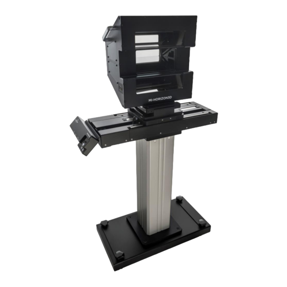
HORIZON3D provides an accurate synchronization function for both current format 72Hz, 24fps, triple flash and future HFR 3D formats. HORIZON3D is perfectly matched to the high quality polarized 3D eyewear produced by MASTERIMAGE 3D. HORIZON3D consists of the three-way beam optical head, actuator, control box, connection cables, and floor stand. -
Page 10: Installation And Configuration
4. Installation and Configuration 4.1. Unpacking the HORIZON3D Inspect the HORIZON3D packaging box for any external damage. Report any damage to shipper and to MasterImage 3D. Floor Stand Outer Carton contains Floor Stand, Actuator, Control Box and Accessories LOW VIBRATION CASE (Vacuum Packaging &... -
Page 11: Confirm Package Contents Of Horizon3D
Installation & Operation Manual | HORIZON3D & HORIZON3D S 4.2. Confirm Package Contents of HORIZON3D Optical Three-Way Beam Head Assembly inside Low Vibration Case Floor Stand Actuator Control Box Power Adaptor Sync Cable ... -
Page 12: Detailed Component Overview
Installation & Operation Manual | HORIZON3D & HORIZON3D S 5. Detailed Component Overview 5.1. Three-Way Beam Optical Head Assembly © MASTERIMAGE 3D, Inc. -
Page 13: Actuator & Control Box
Installation & Operation Manual | HORIZON3D & HORIZON3D S 5.2. Actuator & Control Box 5.3. Floor Stand © MASTERIMAGE 3D, Inc. -
Page 14: Control Box - Front Panel & Connections
Installation & Operation Manual | HORIZON3D & HORIZON3D S Control Box – Front Panel & Connections 5.4. Dip Switch: Operation LED: Used to Displays reverse 3D Actuator Running Freq. polarity & Connector Run/Stop & Error Codes actuator Button position GPIO/TTL... -
Page 15: System Setup
Installation & Operation Manual | HORIZON3D & HORIZON3D S 6. System Setup 6.1. Initial System Assembly 6.1.1. Attach Optical Head to Actuator Insert the optical head assembly into the front section of the actuator tilt stage whilst aligning with the two guide pins. -
Page 16: Cable Connections
Installation & Operation Manual | HORIZON3D & HORIZON3D S 6.1.2. Cable Connections Attach the LC Connector from the Actuator assembly to the Optical Head Assembly. LC Cable Connection Ensure the Actuator Cable is connected between the Control Box and Actuator and the LC Cable is connected to the rear of the Control Box. -
Page 17: Initial Height Adjustment
Installation & Operation Manual | HORIZON3D & HORIZON3D S 6.1.3. Initial Height Adjustment Adjust the height of the optical head so the projected light beam coincides with the center of the optical head entrance window. Clockwise: UP Counter-Clockwise: DOWN ALLEN WRENCH (TYPE-T) 6mm Front: Height Locking Screw. - Page 18 Installation & Operation Manual | HORIZON3D & HORIZON3D S IMPORTANT The Optical Head Assembly must be installed perpendicular to the light path exiting the lens. The angle of this light may not be the same angle as the lens itself, so observe the light path from the side to make sure the head is exactly perpendicular.
-
Page 19: Locking Feet
Installation & Operation Manual | HORIZON3D & HORIZON3D S 6.1.4. Locking Feet Once the height and tilt adjustment has been made, lock down all four rolling wheels to prevent system movement. 6.1.5. GPIO Cable Connect the GPIO cable from the DLP Digital Cinema Projector. -
Page 20: Initial Test
Installation & Operation Manual | HORIZON3D & HORIZON3D S 6.2. Initial Test 6.2.1. Auto Power On To turn on the control box power automatically, connect the main cable from the DC power supply to a power outlet. With no sync signal present the LED display... -
Page 21: System Alignment
Installation & Operation Manual | HORIZON3D & HORIZON3D S 7. HORIZON3D System Alignment & Configuration 7.1. Upper Beam Alignment 1, Open the two adjustment screw covers on the top side of the optical head assembly. 2, Load the standard cross-hair test pattern from the projector. -
Page 22: Lower Beam Alignment
Installation & Operation Manual | HORIZON3D & HORIZON3D S 7.2. Lower Beam Alignment 1, Open the two adjustment screw covers on the bottom side of the optical head assembly. 2, Using the same standard cross-hair test pattern from the projector. -
Page 23: Phase Sync Polarity
Installation & Operation Manual | HORIZON3D & HORIZON3D S 7.3. 3D Phase Sync Polarity If necessary it is possible to change the sync polarity of the 3D phase by changing the position of DIP switch 2 on the Control Box next to the Ethernet RJ-45 Connector. -
Page 24: Projector Configuration
8.1. Projector 3D File Configuration The projector’s 3D control file must be configured to work with the HORIZON3D. These procedures describe configuring the control files for Series II projectors. The Dark Time should be set to 350µS with the Delay being set to -100µS. These figures are applicable to all frame rates and projector flash configurations. -
Page 25: Christie Series Ii File Settings For External Server Playback
Installation & Operation Manual | HORIZON3D & HORIZON3D S 8.2.2. Christie Series II File Settings for External Server Playback Christie 8.2.3. Barco Series II File Settings for External Server Playback Barco © MASTERIMAGE 3D, Inc. -
Page 26: Imb Configuration Settings
Installation & Operation Manual | HORIZON3D & HORIZON3D S Barco Series II projectors have a pre-installed 3D configuration file for the settings required by the MI-CLARITY3D system. It is possible to select this file rather than making fully manual entries, but editing of Dark Time and Output Reference Delay would be required. -
Page 27: System Setup Using The Monitor Application
9. System Setup Using the Monitor Application 9.1. Initial Configuration Connect your PC to the HORIZON3D with an Ethernet cable and configure your network settings with Control Panel of Microsoft Windows. You can use a different IP address that is suitable to your network 9.2. -
Page 28: Changing The User Password
To prevent access to the HORIZON3D from unauthorized persons it is possible to change the system password. Click the [New Password] link in the upper right corner of the HORIZON3D Web Server and the ‘Change Password’ dialog box will be displayed. -
Page 29: System Operation Via The Monitor Application
Installation & Operation Manual | HORIZON3D & HORIZON3D S Input the current password. (mi) • Input a new password. • Input the new password for confirmation and click the [Save password] • button. 9.3. System Operation via the Monitor Application Click the [RUN] button to start the Liquid Crystal Panel operation. -
Page 30: Position Movement Via The Monitor Application
Installation & Operation Manual | HORIZON3D & HORIZON3D S 9.4. Position Movement via the Monitor Application 9.4.1. 3D Position Click the [3D] button to move the actuator to the 3D position. The color of the [3D] button will change from black to green. -
Page 31: Position
Installation & Operation Manual | HORIZON3D & HORIZON3D S 9.4.2. 2D Position Click the [2D] button to move the actuator to the 2D position. The color of the [3D] button will change from green to black. The color of the [2D] button will change from black to green. -
Page 32: Sync Polarity Via The Monitor Application
Installation & Operation Manual | HORIZON3D & HORIZON3D S 9.5. Sync Polarity via the Monitor Application Check the current value of the Sync Polarity. Depending on the condition of 3D material on screen change the Sync Polarity as required from ‘True’ to ‘Invert’. -
Page 33: Setting 3D Position Via The Monitor Application
Installation & Operation Manual | HORIZON3D & HORIZON3D S 9.6. Setting 3D Position via the Monitor Application Check the current setting for the 3D position of the Actuator. If required by the installation requirements for the system the 3D Position can be changed from ‘Left’... -
Page 34: Automation Source Via The Monitor Application
Installation & Operation Manual | HORIZON3D & HORIZON3D S 9.7. Automation Source via the Monitor Application Check the current setting for the Automation Source of the system, by default this is set to ‘Manual’. The options available for selection are: ... -
Page 35: Sync Pulse Automation Reference Frequency Via The Monitor Application
Installation & Operation Manual | HORIZON3D & HORIZON3D S 9.8. Sync Pulse Automation Reference Frequency via the Monitor Application Set the reference frequencies when the automation source is set to Sync Pulse. Once the Automation Source has been set to Sync Pulse click [Reference Sync] in the bottom left of the application. -
Page 36: Delay Time Via The Monitor Application
Installation & Operation Manual | HORIZON3D & HORIZON3D S 9.9. 2D Delay Time via the Monitor Application When using the Sync Pulse Automation option with material of varying frequency or frame rate it may be necessary to apply 2D Delay Time to the system to prevent unwanted 2D transition. -
Page 37: Network Configuration Via The Monitor Application
Installation & Operation Manual | HORIZON3D & HORIZON3D S 9.10. Network Configuration via the Monitor Application Configure the network settings of the HORIZON3D to operate on your network via ethernet communication. Click [Network Configuration] to access the settings window. Enter the IP Address, Gateway, Subnet Mask, Primary DNS and Secondary DNS of your network accordingly. -
Page 38: Sync Source Via The Monitor Application
Installation & Operation Manual | HORIZON3D & HORIZON3D S 9.11. Sync Source via the Monitor Application Check the current setting for the Sync Source. The default is [GPIO]. Choose the option for [TTL] if the system is being used in a non-cinema application. -
Page 39: Log File Via The Monitor Application
Installation & Operation Manual | HORIZON3D & HORIZON3D S 9.12. Log File via the Monitor Application The system contains a log function that stores the last 200 records of activity including any errors that occurred. In order to access the log file click [Log] at the top of the Monitor Application. - Page 40 Installation & Operation Manual | HORIZON3D & HORIZON3D S Description # POWER ON : v1.0.0 Power On : Firmware Version Number RUNNING RUNNING STOP STOP Current Position : 2D 2D MOVING Actuator Moving to 2D Position Current Position : 3D...
-
Page 41: Factory Default Via The Monitor Application
Installation & Operation Manual | HORIZON3D & HORIZON3D S 9.13. Factory Default via the Monitor Application Should it be necessary for any reason to reset the system to Factory Default this can be achieved by clicking the [Default] button. This can be completed for operational settings or network configuration. -
Page 42: Horizon3D Troubleshooting
Installation & Operation Manual | HORIZON3D & HORIZON3D S 10. HORIZON3D Troubleshooting. 10.1. Error Indication via LED Display Check the Control Box LED display for any error indication as per the below table. Error code Description No connection with the Actuator... -
Page 43: Appendix A - Firmware Upgrade Process For Horizon3D
4. Prepare a CAT5-E cable for connection to the system. 11.2. Firmware Upgrade Procedure 1. Connect the HORIZON3D control box to your PC with the Ethernet cable. 2. Execute “MITftp” utility by double-clicking the utility’s icon on your PC. © MASTERIMAGE 3D, Inc. - Page 44 Installation & Operation Manual | HORIZON3D & HORIZON3D S Device’s IP Address TFTP Port number 192.168.10.95) (Default: (Default: 69) Hex file name size Open Hex file Hex file Log message Updating progressive bar Upgrade button Exit button 3. Configure the utility to match your individual site network requirements.
- Page 45 Installation & Operation Manual | HORIZON3D & HORIZON3D S 4. Click the [Open] button to select the firmware (.hex) file saved to your PC. 5. Select the file to be used and click [Open]. 6. Click the [Upgrade] button to start the upgrade of the selected file to the system.
- Page 46 Installation & Operation Manual | HORIZON3D & HORIZON3D S 7. You will see the “Start Firmware Upgrade” message in the utility after pressing the [Upgrade] button. 8. You will see the “Success Firmware Upgrade” message in the utility after the progress bar reaches the end.
-
Page 47: Appendix B - Horizon3D Automation
Installation & Operation Manual | HORIZON3D & HORIZON3D S 12. Appendix B – HORIZON3D Automation Table B-1. GPIO/TTL Automation DSUB(GPIO/TTL) DSUB37 Comm. Description Comments Direction Pin Name Pin Number Pin Number No Connection ← Liquid Crystal Panel Module PRJ_COM_nRUN RUN command... - Page 48 Installation & Operation Manual | HORIZON3D & HORIZON3D S Table B-2. GPIO/TTL Automation DSUB(GPIO/TTL) DSUB37 Comm. Description Comments Direction Pin Name Pin Number Pin Number Compartor ← 24V max, PRJ_SYNC SYNC pulse 12V threshold (LM2901H) 13,14 Ground CHASSIS_GND Frame Frame Chassis Ground ©...
-
Page 49: Ethernet Automation
Installation & Operation Manual | HORIZON3D & HORIZON3D S 12.1. Ethernet Automation This section covers the requirements for Ethernet automation in detail and explains the process for the writing of macros for commonly found digital cinema servers in the market. - Page 50 Installation & Operation Manual | HORIZON3D & HORIZON3D S The HORIZON3D has now been successfully added into the server configuration. It is now possible to create the macro files to enable the server to control the HORIZON3D. The files required are: MasterImage Start, MasterImage Stop, MasterImage 2D, MasterImage 3D and MasterImage Up/Down Stop.
- Page 51 Installation & Operation Manual | HORIZON3D & HORIZON3D S 2. After the item has been created click OK return to the main Macro Editor screen. Repeat this process for the other four required macros, MasterImage Stop, MasterImage 2D, MasterImage 3D and MasterImage Up/Down Stop.
- Page 52 Installation & Operation Manual | HORIZON3D & HORIZON3D S 4. Highlight the Input/Output option and Send Message, and then click the Add button. The following configuration window will appear: 5. In this window, choose the device MasterImage from the Device name dropdown list and type in the Message label of MasterImage Start.
- Page 53 Installation & Operation Manual | HORIZON3D & HORIZON3D S In future versions of Doremi software updates, the MasterImage macros will be included in a file named MasterImage_cueslib. This will remove the requirement for the information to be entered manually as described in the above steps.
- Page 54 Installation & Operation Manual | HORIZON3D & HORIZON3D S © MASTERIMAGE 3D, Inc.
-
Page 55: Qube Server
12.1.2. Qube Server To create automation macros for the HORIZON3D in the Qube server it is necessary to edit two XML files within the server’s configuration. The files in question are located in the path C:/Program Files/Qube Cinema/XP and are named automationdevices.xml and automationcues.xml... - Page 56 Finally the automationcues.xml file can be edited so that the HORIZON3D device is associated with the command names that have been created. This allows the cues to be seen in the Qube graphical interface.
- Page 57 Installation & Operation Manual | HORIZON3D & HORIZON3D S <Cue name="Start 3D"> <Actions> <InvokeMethod name="Start" device="MasterImage"/> </Actions> </Cue> <Cue name="Stop 3D"> <Actions> <InvokeMethod name="Stop" device="MasterImage"/> </Actions> </Cue> <Cue name="3D Position"> <Actions> <InvokeMethod name="3Dposition" device="MasterImage"/> </Actions> </Cue> <Cue name="2D Position"> <Actions>...
-
Page 58: Gdc Server
Installation & Operation Manual | HORIZON3D & HORIZON3D S 12.1.3. GDC Server The steps described below are specific to the GDC SX-2001 server. If information is required for different models, please contact GDC directly. 1. In the SMS Main Menu click the Control Panel button and log on as Maintenance Access. - Page 59 Installation & Operation Manual | HORIZON3D & HORIZON3D S The HORIZON3D must be added as a device within the GDC server configuration. 3. Select the Devices tab and click the Add button. The following screen will display: © MASTERIMAGE 3D, Inc.
- Page 60 4. Name the new device MasterImage, and ensure the Type selection is set to NETWORKSOCKET, then click OK. 5. In the next screen, enter the configuration settings for the HORIZON3D IP Address and Port Number. 6. In the Transport option select TCP and in the Linefeed Type select CR and ensure the Status is set to Enabled.
- Page 61 Installation & Operation Manual | HORIZON3D & HORIZON3D S 9. Click the Add button to create a new event. In this case, name the event START. 10. Click the Enter button and enter the command value for the event. Again in this case, START.
- Page 62 Installation & Operation Manual | HORIZON3D & HORIZON3D S 11. Click the Enter button to save this change, then go back and make entries for the remaining four macros that are required. Event Name STOP Enter Value STOP Event Name 2D POSITION...
- Page 63 Installation & Operation Manual | HORIZON3D & HORIZON3D S 15. Once all event actions have been created click the Save button followed by Yes. © MASTERIMAGE 3D, Inc.
-
Page 64: Appendix C - Installation Record
Installation & Operation Manual | HORIZON3D & HORIZON3D S 13. Appendix C – Installation Record The form below is an example of the installation record form to be filled out once the HORIZON3D has been set up and configured. For a copy of the form to be filled out, ‘contact your equipment provider or email a request to support@masterimage3d.com. - Page 65 Installation & Operation Manual | HORIZON3D & HORIZON3D S 14. Appendix D – Dimensional Drawings © MASTERIMAGE 3D, Inc.
- Page 66 Installation & Operation Manual | HORIZON3D & HORIZON3D S Optical Head Assembly © MASTERIMAGE 3D, Inc.
- Page 67 Installation & Operation Manual | HORIZON3D & HORIZON3D S End of Manual For additional information, go to www.support.masterimage3d.com. © MASTERIMAGE 3D, Inc.
Need help?
Do you have a question about the HORIZON3D and is the answer not in the manual?
Questions and answers