
Related Manuals for Master Image MI-2100R


Summary of Contents for Master Image MI-2100R
- Page 1 MI-2100R Stereoscopic Digital 3D System Installation & Operations Manual All Rights Reserved Copyright 2011 MASTERIMAGE 3D, INC...
- Page 2 MI-2100R Installation & Operations Manual Revision History Revision Release Status Author Remarks Rev A, Date 9-23-11 Initial Release Rev B, Date 11-01-11 Minor Amendments...
- Page 3 All information contained in or disclosed by this document is confidential and proprietary to MASTERIMAGE 3D, INC. (hereinafter referred to as MASTERIMAGE). By accepting this material, the recipient agrees that this material and information contained herein will be held in confidence and will not be reproduced in whole or in part, without the prior expressly written permission of MASTERIMAGE 3D, INC.
-
Page 4: Table Of Contents
........................................14 MI-2100R ....................... 15 OSITIONING AND ONFIGURING THE 4.3.1 MI-2100R positioning ............................... 15 4.3.2 Fine-adjusting the image position on the MI-2100R filter ..................17 Locking the MI-2100R’s wheels in place ......................... 18 4.3.3 ..................................19 ONNECTIONS ..............................20 ROJECTOR ETUP 4.5.1... - Page 5 ..............................61 IMENSIONS ..............................62 RODUCT PECIFICATIONS APPENDIX A – TURNING THE FILTER HEAD – OPTIONAL STEP ..................63 APPENDIX B – MI-2100R AUTOMATION ..........................66 ....................................66 UTLINE MI-2100R Wiring & Automation…………………………………………………………………………………66 MI-2100R Ethernet Automation….……………………………………………………………………………..70 Doremi Server Configuration…………………………………………………………………………….70 Qube Server Configuration………………………………………………………………………………76 GDC Server Configuration………………………………………………………………………………79...
-
Page 6: Introduction
1.1 Welcome Congratulations on choosing the finest digital projection 3D system available. The MASTERIMAGE MI-2100R delivers the clearest full color images in a cost effective and studio approved single projection digital 3D system. Paired with MASTERIMAGE high quality 3D eyewear, the MI-2100R provides the clearest and truest color 3D picture of any single filter 3D system available. -
Page 7: Warnings And Cautions
2.2 Burning Filter Warning In order to avoid burning the polarizer filters, the MI-2100R filter wheel must be lowered or moved out of the light path during lamp adjustments. In general the filter should always be turning when it is in the light path of the projector. -
Page 8: System Overview
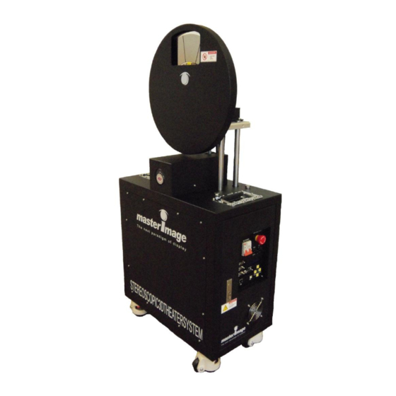
MI-2100R Installation & Operations Manual 3 System Overview 3.1 Key Product Components Filter Head Assembly & Polarization Filter Disk (PFD) Lifting Rail Up/Down Drive Motor System Control Panel Power Cable Lockable Wheels... -
Page 9: Control Panel
MI-2100R Installation & Operations Manual 3.2 Control Panel EMERGENCY Stop Button AC POWER Breaker RUN/STOP Switch PFD Position Control Switch Status LED Projector Sync input and GPIO Automation S/W version info RS-232C Current Time Automation Status TTL Sync input... -
Page 10: General Operating Principles
MI-2100R Installation & Operations Manual 3.3 General Operating Principles... -
Page 11: Installation And Configuration
2. Carefully remove the crate fasteners and crate top and sides using an 8mm socket and power tools. 3. Loosen the shipping straps and remove the protective wrap. 4. Insure all items are included: MI-2100R, cover, installation kit box, spare polarizing filer disk. MI-2100R Installation Kit Box 4.1.1 Unpacking and preparing the MI-2100R’s rolling wheels... -
Page 12: Orienting The Mi-2100 In Front Of The Digital Projector
MI-2100R Installation & Operations Manual 4.2 Orienting the MI-2100 in front of the Digital Projector There are four ways the filter head and main base can be oriented in order to best "fit" the space of the projection booth and projector. -
Page 13: Orientation 2 - Standard Left
MI-2100R Installation & Operations Manual 4.2.2 Orientation 2 - Standard Left With overhanging lenses, as commonly found in Christie projectors, the system may be set with the control panel facing the left side of the projector in order to be more convenient to the operator or to deal with floor space issues. -
Page 14: Orientations 3 & 4 - Reversed Filter Head Right And Left
MI-2100R Installation & Operations Manual 4.2.3 Orientations 3 & 4 - Reversed Filter Head Right and Left. In rare cases where the lens, projector, floor space or port window do not allow for "standard positioning" of the filter head, the filter head can be removed and "reversed" in order to work in the unique spacing requirements and to get the filter disk as close to the lens as required (1/4"... -
Page 15: Positioning And Configuring The Mi-2100R
4.3 Positioning and Configuring the MI-2100R Position and configure the MI-2100R as described in the procedures below. 4.3.1 MI-2100R positioning 1. Position the MI-2100R centrally with the projector lens and adjust the filter wheel height using UP/DOWN switch. Adjustable height Note: This switch can only be used when the filter is not spinning. - Page 16 Result: When in position, the MI-2100R filter wheel should be parallel to the projector lens from both the top and side views. Insure all motor mount screws and nuts are tight.
-
Page 17: Fine-Adjusting The Image Position On The Mi-2100R Filter
Do not make position adjustments with the filter turning. 1. Project an image onto the screen 2. Fine-adjust the position of the image on the MI-2100R filter so that it is centered just below the edge of the filter’s area. -
Page 18: Locking The Mi-2100R's Wheels In Place
Push the orange ring to the right to bring each footpad down and secure the MI-2100R. Note: If the MI-2100R is on an uneven floor all four foot pads must be down to ensure stability. Releasing the footpads to move the MI-2100R... -
Page 19: Connections
4.4 Connections 1. Make sure that the MI-2100R’s power is off. 2. Connect the supplied Sync cable to the MI-2100R and the GPIO port of the projector, as shown in the illustration above. 3. Check that the red Emergency Stop button was not pressed during system unpacking or... -
Page 20: Projector File Setup
MI-2100R Installation & Operations Manual 4.5 Projector File Setup It is necessary to configure the projector’s 3D control file to work with the MI-2100R. The procedures below describe configuring the control files for Series I and Series II projectors. Follow the instructions for the appropriate projector. -
Page 21: Series Ii Projectors
In certain installations, where space is restricted in front of the projector or if the lens protrudes a long way, it may be necessary to install the MI-2100R the opposite way around, that is, with the PFD motor under the lens. - Page 22 MI-2100R Installation & Operations Manual NEC Series II file settings for external server playback Note: Settings for NEC where the projector Firmware Release Pack is lower than v2.33 are different from both Christie and Barco file configurations. This projector should have the L/R Input Reference field set to Use selected Input port (polarity=true).
- Page 23 MI-2100R Installation & Operations Manual Barco Series II file settings for external server playback Notes: The Barco projectors should have the field L/R Input Reference field set to Use line interleave (First line = Left, second line = right).
-
Page 24: Basic Operation Of The Mi-2100R
MI-2100R Installation & Operations Manual 4.6 Basic Operation of the MI-2100R 4.6.1 System Ready (Standby Condition) With the projector in 3D mode/channel, ensure that the MI-2100R’s Main Power switch is ON and the system is ready to start. Readiness is indicated by: ... -
Page 25: Up/Down Drive Motor
MI-2100R Installation & Operations Manual 4.7 Up/Down Drive Motor 4.7.1 Up/Down Operation In order to raise up the filter wheel before running the 3D system, the operator has to push up the Up/Down switch until the filter wheel is adjusted to the projector lens. -
Page 26: Detailed Setup And Configuration Of The Mi-2100R
MI-2100R Installation & Operations Manual 4.8 Detailed Setup and Configuration of the MI-2100R 4.8.1 Menu Structure 1st Level 2nd Level Item No. Remark (Capital Letter) (Lower Case Letter) Set the local date and time. ‘Enter’ key: HH(hour) => MM(minute) => YYYY(year, 2010~2032) =>... - Page 27 MI-2100R Installation & Operations Manual 4.Home Select PFD synchronization source Position Factory Default Setting: A. Motor A. Motor Use the motor encoder to synchronize PFD rotation. During the setup process for motor encoder synchronization the optical sensor is used. B. Sensor + Motor During operation the motor encoder is used to synchronize PFD rotation.
-
Page 28: Clock Setting
MI-2100R Installation & Operations Manual Configure the necessary settings for Ethernet communication. Factory Default Setting: 7.Ethernet IP : 192. 168. 0. 255 SM: 255. 255. 255. 0 GW: 192. 168. 0. 1 Port: 23 A. Local IP IP XXX.XXX.XXX.XXX Set Local IP address. -
Page 29: Sync Source Selection
MI-2100R Installation & Operations Manual Once the correct time and date have been set, press the ‘Menu’ key twice to return to the standby condition. ‘Menu’ twice 4.8.3 Sync Source Selection 4.8.3.1 Sync Select To set the 3D synchronization input port that is to be used press the ‘Menu’ key twice followed by ‘Enter’... - Page 30 MI-2100R Installation & Operations Manual ‘Down’ twice Optional Sync Source Pin Configuration GPIO Connector DSUB9(GPIO) Comm. DSUB37 Description Comments Direction Pin name Pin number Pin number PRJ_SYNC 9(+) Vertical sync pulse Comparator 24V max, 28(-) 12V threshold (LM2901H) 3D Port Connector DSUB15(3D-Port) Comm.
-
Page 31: Automation Source
4.8.4 Automation Source Options are available to automate the control of the MI-2100R for both 2D and 3D movie presentation. As a default all controls are set to be operated from the user control panel on the... -
Page 32: Home Position Setting
In this condition the rotational synchronization of the PFD is maintained using the encoder pulse from the PFD drive motor. This setting should not be altered for normal operation of the MI-2100R. Note: This setting can be altered on an upgraded MI-2100 as this system contains an optical... -
Page 33: Phase
4.8.6.1 Switch Phase Depending on the installation orientation of the MI-2100R it may be necessary to switch the phase of the 3D signal once the image is viewed on screen. The default setting for this item is “off”, if the image is seen as sudo-3D change this setting to “on”. - Page 34 4.8.6.3 Offset Adjustment During the initial installation of the MI-2100R, after PFD replacement or Factory Default has been reset it is necessary to ‘teach’ the system the 3D synchronization position for the PFD. Note: This operation is not required in an upgraded MI-2100 if the “Home Position” is set to “Sensor”...
- Page 35 MI-2100R Installation & Operations Manual Push up and release the ‘Run/Stop’ switch and the PFD will start to rotate slowly whilst the system detects the 3D synchronization offset position. Adjustment Complete The image on the right above will only be displayed for a couple of seconds, the screen will return to the menu item “C.
-
Page 36: Factory Default
4.8.8 Ethernet Configuration If you wish to use the Ethernet communication option of the MI-2100R for automation then it is necessary to configure the settings to match that of your local area network. - Page 37 MI-2100R Installation & Operations Manual 4.8.8.1 IP Address ‘Enter’ ‘Enter’ In the image to the left the 1 digit in the IP address can be seen as flashing, this can be set to whatever is required by the local network using the ‘Up/Down’...
- Page 38 MI-2100R Installation & Operations Manual In the image to the right above the 1 digit in the Gateway can be seen as flashing, this can be set to whatever is required by the local network using the ‘Up/Down’ keys. Each press of the ‘Enter’ key will advance the flashing digit to the next number in the Gateway;...
-
Page 39: Up/Down Drive Motor
MI-2100R Installation & Operations Manual advance the flashing digit to the next number in the Port; make adjustments as necessary followed by a press of the ‘Menu’ key which will take you back to “D. Port”. Once all of the Ethernet configuration settings have been made to suit the local area network pressing the ‘Menu’... -
Page 40: Installation Checklist
Check SYNC Cable connection between MI-2100R and Projector Check the Projector lens and MI-2100R filter are parallel and that the base wheels are locked. Check location of the projected image on the top center of MI-2100R filter. -
Page 41: Mi-2100R Daily Operation
2. Insure that the projector is set in the required 3D mode – 3D Flat or Scope. 3. On the MI-2100R control panel, turn on the main MI-2100R power switch. 4. Confirm that the operation LCD displays proper system status. -
Page 42: Starting A 3D Show
On the MI-2100R control panel, push down the ‘Run/Stop’ switch to stop the filter wheel. For the next show, the filter wheel must be started again manually using the ‘Run/Stop’ switch. -
Page 43: Maintenance
Any PFD’s without a “PC” label must be changed immediately due to risk of possible material failure. Unplug the MI-2100R power cord and sync cable, and move it out from in front of the projector in order to have good access and lighting to work on the filter head assembly. - Page 44 MI-2100R Installation & Operations Manual twelve outer screws holding it in place followed by the center PFD position guide and screw. 1) PFD 2) PFD Position Guide 3) PFD Position Guide Screw 4) PFD Outer Screws and Washers IMPORTANT: ONLY use a hand screwdriver to loosen and tighten the PFD screws.
- Page 45 MI-2100R Installation & Operations Manual Carefully remove the filter from the drive hub. Set the old filter aside and immediately mark it with a Sharpie as follows: “Used, removed on [add date]”. Wipe any dust off of the filter cover back with a suitable cleaning cloth (not the filter cleaning cloth).
- Page 46 MI-2100R Installation & Operations Manual Note: This film should be dull and easily removed – if the filter is shiny, these pieces have already been removed. iii) Lastly, peel off the sticky film from the clear side of the filter.
- Page 47 MI-2100R Installation & Operations Manual The polarizing filter material side of the PFD must always face the screen. Carefully place the filter on the hub and assemble the PFD Position Guide. To secure the filter, do the following: i) Insert the countersunk PFD Position Guide Screw; do not tighten at this time.
- Page 48 After a successful check, stop the filter, power off the system, and unplug the power cable. 12. Move the MI-2100R back into proper position in front of the projector lens, and check that the filter side of the PFD is facing the screen.
-
Page 49: Cleaning The Filter
MI-2100R Installation & Operations Manual 6.2 Cleaning the filter 6.2.1 Materials Required To ensure that filter is cleaned safely, use materials as specified below: Use only approved micro fiber type polishing cloths. These cloths feel extra soft to the touch with absolutely no abrasive texture. - Page 50 MI-2100R Installation & Operations Manual 1. If possible, unlock the wheels and move the MI-2100R away from the projector lens to an area with bright lighting. If the unit cannot be moved out to an open space, lower the filter below the lens using the ‘Up/Down’...
- Page 51 PFD using bright light such as flash light. If there is any damage on polarizing filter disk, please replace it with spare PFD. Note: If not using the MI-2100R for several days, protect the filter wheel with a clean cover. For any other cleaning questions contact MASTERIMAGE 3D directly at...
-
Page 52: Filter Removal And Turning
MI-2100R Installation & Operations Manual 6.3 Filter Removal and Turning 1. Unplug the MI-2100R power cord and sync cable, and move it out from in front of projector in order to have good access and lighting for work on the filter head assembly. - Page 53 MI-2100R Installation & Operations Manual 1) PFD 2) PFD Position Guide 3) PFD Position Guide Screw 4) PFD Outer Screws and Washers 4. Carefully remove the filter from the drive hub. CAUTION NOTICE Projectionist or Operator should inspect the surface of PFD to check any damage on the PFD using bright light such as flash light.
- Page 54 MI-2100R Installation & Operations Manual Note: The polarizing filter material side of the PFD must always face the screen. 6. Carefully place the filter on the hub and assemble the PFD Position Guide. 15. To secure the filter, do the following: Insert the countersunk PFD Position Guide Screw;...
- Page 55 After a successful check, stop the filter, power off the system, and unplug the power cable. 9. Move the MI-2100R back into proper position in front of the projector lens, and check that the filter side of the PFD is facing the screen.
-
Page 56: Problems/Troubleshooting
7.1.1 Checking and Replacing Fuses If the system is plugged in and the MI-2100R’s LCD display on the control panel does not light up when the power breaker is switched to “ON”, then it is necessary to check the main power fuses. -
Page 57: Up/Down Faults
6. Install the good fuses and any replacements and close the fuse holders and base door. 7. Plug in the MI-2100R and turn on the power breaker. If fuses blow again or if the fuses are fine and not the problem then contact your local service... - Page 58 MI-2100R Installation & Operations Manual 7.3.1.2 Running Condition The image below indicates that the PFD is spinning. The unit is in Normal operating condition with no errors. 7.3.1.3 Emergency State The image below shows the Servopak indication at the time the Emergency Stop button has been pressed, the ‘-‘...
-
Page 59: Error Conditions
MI-2100R Installation & Operations Manual LED will be red, at this time no system operation is possible. To return to the Standby condition, release the Emergency Stop button. 7.3.2 Error Conditions 7.3.2.1 CN1 Connection Problem The images below indicate that there is a connection error with Servopak cable CN1, please check the connection of this cable at both the Servopak and system control board ends. - Page 60 MI-2100R Installation & Operations Manual The LCD display will show as below with a ‘Red’ status LED: 7.3.2.2 CN2 Connection Problem The images below indicate that there is a connection error with Servopak cable CN1, please check the connection of this cable at both the Servopak and system control board ends.
-
Page 61: Technical Specifications
MI-2100R Installation & Operations Manual 8 Technical Specifications 8.1 MI-2100R Dimensions Center of Picture height: 40 3/4” 1034mm 54 1/8” 1374mm Base: 12 1/2” Depth 315mm 21 5/8” Width 550mm 22 1/2” Height 572mm Filter wheel Assembly: 8 1/16” Depth... -
Page 62: Product Specifications
MI-2100R Installation & Operations Manual 8.2 Product Specifications Item Unit SPEC Voltage 200~230V Electrical Current Hertz 50/60 Height (MAX) 1452 Height (MIN) 1112 Dimensions Width Depth Weight 62.7 Operating 10 to 40 Temperature 4:2, 24 fps 2880 Filter Speed 6:2, 24 fps... -
Page 63: Appendix A - Turning The Filter Head - Optional Step
Orientations 3 & 4 - Reversed Filter Head Right and Left. 1. Raise the filter motor at least 8cm from its bottom stop position. 2. Power off and unplug the MI-2100R. 3. Clip tie wrap, slide down cable sheath and undo motor power and signal cables. - Page 64 MI-2100R Installation & Operations Manual 4. Remove the filter and motor assembly. 5. In order to reinstall the turned filter head the cable will have to be moved in order to be feed through the hole in the silver mounting base. Clip the tie wrap and feed the cables as shown below.
- Page 65 & down (see Up/Down Drive Motor) and moving the bracket in its slide in order to position the filter close to the lens at the correct height (see Orienting the MI-2100R in front of the Digital Projector).
-
Page 66: Appendix B - Mi-2100R Automation
MI-2100R Installation & Operations Manual Appendix B – MI-2100R Automation Outline i) MI-2100R Wiring & Automation Control Panel Layout. - Page 67 MI-2100R Installation & Operations Manual GPIO Automation. DSUB9(GPIO) Comm. DSUB3 Direction Description Comments Pin name number number No connection PRJ_COM_nRUN 12(+) PFD RUN command Comparator 24V max, 31(-) PRJ_SYNC 9(+) Vertical sync pulse threshold 28(-) (LM2901H) PRJ_COM_nUP...
- Page 68 MI-2100R Installation & Operations Manual TTL Automation DSUB9(TTL) Comm. DSUB9 Direction Pin name Description Comments number number No connection Transmitter RS-232 Driver Receiver (Max :±25V) (ST3232EC No connection Ground No connection No connection AUTO4_SYNC TTL Level SYNC input...
- Page 69 MI-2100R Installation & Operations Manual 3D Port Automation. DSUB15(3D-Port) Comm. DSUB15 Direction Pin name Description Comments number number V12A +12V Max:1A Ground Ground AUTO2_TXD Transmitter RS-232 Driver Receiver (Max: ±25V) AUTO2_RXD (ST3232ECT AUTO2_3D_ 6(+) MODEP 3D Mode State AUTO2_3D_ ...
-
Page 70: Ii) Mi-2100R Ethernet Automation
MI-2100R Installation & Operations Manual ii) MI-2100R Ethernet Automation Function This section covers the requirements for Ethernet automation in detail and explains the process for the writing of macros from commonly found digital cinema servers in the market. Only attempt these steps if you familiar with server configuration settings. If you are unsure of the processes involved please contact the respective manufacturer of your equipment for further information. - Page 71 The MI-2100R has now been successfully added into the server configuration. It is now possible to create the macro files to enable the server to control the MI-2100R. The files required are: MasterImage Start, MasterImage Stop, MasterImage 2D, MasterImage 3D &...
- Page 72 MI-2100R Installation & Operations Manual Within the ‘Automation Cue’ tab press the ‘+’ button to start a new macro, replace the default ‘Test_Macro’ text with the labels for the MI macros. i.e. MI Start. After the item has been created press ‘OK’ and you will be taken back to the main Macro Editor screen.
- Page 73 MI-2100R Installation & Operations Manual Highlight the ‘Input/Output’ option and ‘Send Message’, and then press the ‘Add’ button; the following configuration window will appear: In this window choose the device ‘MasterImage’ from the ‘Device name’ dropdown list and type in the ‘Message label’...
- Page 74 MI-2100R Installation & Operations Manual Repeat this step for the remaining four macros entering the corresponding message text: MasterImage Stop Stop\n MasterImage 2D PFD DOWN\n MasterImage 3D PFD UP\n MasterImage Up/Down Stop PFD Stop\n Note: At the end of each command it is necessary to add the text ‘\n’ to complete the command.
- Page 75 MI-2100R Installation & Operations Manual The ‘MasterImage_cueslib’ file will be found in the ‘Library’ section of the Macro Editor and the macros will be seen within that file.
-
Page 76: B) Qube Server Configuration
MI-2100R Installation & Operations Manual b) Qube Server Configuration. To create automation macros for the MI-2100R in the Qube server it is necessary to edit two XML files within the servers’ configuration. The files in question are located in the path C:/Program Files/Qube Cinema/XP and are named automationdevices.xml and automationcues.xml... - Page 77 Finally the automationcues.xml file can be edited so that the MI-2100R device is associated with the command names that have been created; this allows the cues to be seen in the Qube graphical interface.
- Page 78 MI-2100R Installation & Operations Manual The information added to this file should be: <Cue name="Start 3D"> <Actions> <InvokeMethod name="Start" device="MasterImage"/> </Actions> </Cue> <Cue name="Stop 3D"> <Actions> <InvokeMethod name="Stop" device="MasterImage"/> </Actions> </Cue> <Cue name="3D Position"> <Actions> <InvokeMethod name="3Dposition" device="MasterImage"/> </Actions> </Cue>...
-
Page 79: C) Gdc Server Configuration
MI-2100R Installation & Operations Manual c) GDC Server Configuration The steps described below are specific to the GDC SX-2001 server, if information is required for differing models please contact GDC directly. In the SMS Main Menu press the ‘Control Panel’ button and logon as ‘Maintenance Access’. - Page 80 MI-2100R Installation & Operations Manual It is necessary to add the MI-2100R as a device within the GDC server configuration. Select the ‘Devices’ tab and press the ‘Add’ button.
- Page 81 Name the new device ‘MasterImage’, ensure the ‘Type’ selection is set to ‘NETWORKSOCKET’ and press ‘OK’. In the next screen we enter the configuration settings for the MI-2100R for IP Address and Port Number. In the ‘Transport’ option select ‘TCP’ and in the ‘Linefeed Type’ select ‘CR’ and ensure the ‘Status’...
- Page 82 MI-2100R Installation & Operations Manual In the last step it is necessary to program the control macros in the server. Press the ‘Edit Control Cues’ button and you will see the following screen. Press the ‘Add’ button to create a new event, in this case name the event ‘START’.
- Page 83 MI-2100R Installation & Operations Manual Press the ‘Enter’ button and enter the command value for the event, again in this case, ‘START’. Once this has been saved by pressing the ‘Enter’ button, go back and make entries for the remaining four macros that are required.
- Page 84 MI-2100R Installation & Operations Manual Once all event actions have been created press the ‘Save’ button followed by ‘Yes’.
-
Page 85: Power & Signal Line Connection
MI-2100R Installation & Operations Manual Power & Signal LINE Connection i) MI-2100R Wiring Diagram Module Wiring Diagram... - Page 86 MI-2100R Installation & Operations Manual Automation Signal Input/ Output...
-
Page 87: Sequence Timing
MI-2100R Installation & Operations Manual Sequence timing Automatic Control Timing Chart using GPIO Automatic Control Timing Chart using Serial Communication... - Page 88 Operation Timing (1) Up Automatic Operation Mode delivery time (2) Down Automatic Operation Mode delivery time (3) MI-2100R Filter Up Position time for suitable Projector Lens height (4) MI-2100R Filter Down Position time for 2D Movie Playing Adjust 3D Fitter Position...
-
Page 89: Appendix C - Firmware Upgrade Process
Appendix C – Firmware Upgrade Process a. Software Installation. In order to upgrade the MI-2100R firmware version it is necessary to first install the DfuSe software package from S T Microelectronics to your computer, follow the instructions below to complete this process. - Page 90 MI-2100R Installation & Operations Manual The setup process will now indicate the folder in which the software will be installed, this can be changed if necessary but it is advised to leave the settings as default. Pressing the ‘Next’ button will start the installation process.
- Page 91 MI-2100R Installation & Operations Manual b. Hardware Preparation. In order for the S T Microelectronics DfuSe software to communicate with the MI-2100R it is necessary to place the system into DFU mode. With the system power breaker in the ‘Off’ position, press and hold any one of the four yellow ‘Menu’...
- Page 92 MI-2100R Installation & Operations Manual c. Software Connection and Firmware Upgrade. From the Start menu select the ‘DfuSe Demonstration’ program from within the S T Microelectronics folder. The software will open in a disconnected mode, click on the drop-down arrow highlighted above to see a list of available devices.
- Page 93 Press the ‘Open’ button and the firmware file will load to the DfuSe software program, this is indicated in the green bar at the bottom of the software window. Press the ‘Upgrade’ button to begin the upgrade process of the MI-2100R, a final warning stage will be given, press ‘Yes’ to continue the upgrade.
- Page 94 MI-2100R Installation & Operations Manual d. Confirmation of Successful Upgrade. Power ‘Off’ and ‘On’ the AC Power breaker of the MI-2100R and ensure that the LCD display now indicates the newly installed firmware version.
-
Page 95: Appendix D - Installation Record Form
The form below is an example of the installation record form that you fill out once you have completed setting up and configuring the MI-2100R. For a copy of the form to be filled out, please contact your equipment provider or email support@masterimage3d.com. -
Page 96: Appendix E - Regular Maintenance Work
MI-2100R Installation & Operations Manual Appendix E – Regular Maintenance Work The below table show the least regular maintenance points carried out by operator in cinema. To guarantee reliable system operation, weekly, monthly and yearly routine maintenance points should be conducted like manual description or other technical bulletin that MASTERIMAGE released. - Page 97 MI-2100R Installation & Operations Manual End of Manual Page is intentionally blank.
- Page 98 MI-2100R Installation & Operations Manual...
Need help?
Do you have a question about the MI-2100R and is the answer not in the manual?
Questions and answers