AudioCodes MediaPack MP-108 User Manual
Mediapack series, cpe & access gateway products, analog voip gateways, sip
Hide thumbs
Also See for MediaPack MP-108:
- User manual (238 pages) ,
- Installation manual (48 pages) ,
- Installation instructions (5 pages)
Table of Contents
Advertisement
Quick Links
Download this manual
See also:
Installation Manual
Advertisement
Table of Contents

Subscribe to Our Youtube Channel
Related Manuals for AudioCodes MediaPack MP-108


Summary of Contents for AudioCodes MediaPack MP-108
- Page 1 MediaPack SIP User’s Manual Version 4.6 Document #: LTRT-65405...
- Page 2 Notice This document describes the AudioCodes MediaPack series Voice over IP (VoIP) gateways. Information contained in this document is believed to be accurate and reliable at the time of printing. However, due to ongoing product improvements and revisions, AudioCodes cannot guarantee accuracy of printed material after the Date Published nor can it accept responsibility for errors or omissions.
-
Page 3: Table Of Contents
MediaPack SIP User’s Manual Contents Table of Contents Overview ........................17 Introduction .............................17 Gateway Description........................17 SIP Overview ..........................18 MediaPack Features........................19 1.4.1 General Features ........................19 1.4.2 MP-1xx Hardware Features ....................19 1.4.3 MP-11x Hardware Features....................19 1.4.4 SIP Features ...........................20 MediaPack Physical Description................23 MP-1xx Physical Description ......................23 2.1.1 MP-1xx Front Panel ........................23 2.1.1.1... - Page 4 MediaPack SIP 5.2.3 Disabling the Embedded Web Server..................48 Accessing the Embedded Web Server...................48 5.3.1 Using Internet Explorer to Access the Embedded Web Server..........49 Getting Acquainted with the Web Interface ..................49 5.4.1 Main Menu Bar........................50 5.4.2 Saving Changes........................50 5.4.3 Entering Phone Numbers in Various Tables................50 Protocol Management........................51 5.5.1 Protocol Definition Parameters ....................51...
- Page 5 MediaPack SIP User’s Manual Contents 5.6.5 Changing the MediaPack Username and Password ............146 Status & Diagnostics........................147 5.7.1 Gateway Statistics ........................147 5.7.1.1 IP Connectivity......................147 5.7.1.2 Call Counters ......................148 5.7.1.3 Call Routing Status .....................150 5.7.2 Monitoring the MediaPack Channels ..................151 5.7.3 Activating the Internal Syslog Viewer ...................153 5.7.4 Device Information ........................154 Software Update ...........................155...
- Page 6 MediaPack SIP 8.11.4 Remote IP Extension between FXO and FXS ..............189 8.11.4.1 Dialing from Remote Extension ..................189 8.11.4.2 Dialing from other PBX line, or from PSTN ..............190 8.11.4.3 FXS MediaPack Configuration (using the Embedded Web Server)......190 8.11.4.4 FXO MediaPack Configuration (using the Embedded Web Server) ......191 Networking Capabilities..................
- Page 7 15.7.4.2 Trap Managers Configuration via the ini File..............237 15.7.4.3 Trap Mangers Configuration via SNMP..............237 15.8 SNMP Manager Backward Compatibility..................239 15.9 AudioCodes’ Element Management System ................239 16 Configuration Files....................241 16.1 Configuring the Call Progress Tones and Distinctive Ringing File..........241 16.1.1 Format of the Call Progress Tones Section in the ini File ............241 16.1.2 Format of the Distinctive Ringing Section in the ini File ............243...
- Page 8 MediaPack SIP B.11.6 Using Command Line Switches ....................266 B.12 Managing Client Templates......................267 Appendix C RTP/RTCP Payload Types and Port Allocation ........269 Packet Types Defined in RFC 3551 .....................269 Defined Payload Types.........................269 Default RTP/RTCP/T.38 Port Allocation..................270 Appendix D Accessory Programs and Tools ............271 TrunkPack Downloadable Conversion Utility................271 D.1.1 Converting a CPT ini File to a Binary dat File...............272...
- Page 9 MediaPack SIP User’s Manual Contents List of Figures Figure 1-1: Typical MediaPack VoIP Application .....................18 Figure 2-1: MP-108 Front Panel ........................23 Figure 2-2: MP-124 Front Panel ........................23 Figure 2-3: MP-104/FXS Rear Panel Connectors ....................25 Figure 2-4: MP-124 (FXS) Rear Panel Connectors..................26 Figure 2-5: MP-118 Front Panel Connectors ....................27 Figure 2-6: MP-118 Rear Panel Connectors ....................28 Figure 3-1: Desktop or Shelf Mounting......................30...
- Page 10 MediaPack SIP Figure 5-34: VLAN Settings Screen .......................125 Figure 5-35: Security Settings Screen......................127 Figure 5-36: Voice Settings Screen........................134 Figure 5-37: Fax / Modem / CID Settings Screen ..................136 Figure 5-38: RTP Settings Screen........................139 Figure 5-39: Hook-Flash Settings Screen ......................141 Figure 5-40: Configuration File Screen......................144 Figure 5-41: Regional Settings Screen......................145 Figure 5-42: Change Password Screen ......................146 Figure 5-43: IP Connectivity Screen.......................147...
- Page 11 MediaPack SIP User’s Manual Contents Figure D-4: Prerecorded Tones Screen ......................274 Figure D-5: File Data Window ........................275 Figure D-6: Initial Settings Screen........................276 Figure D-7: Recording Screen –Automatic Mode...................277 Figure D-8: Recording Screen after Automatic Detection ................278 Figure D-9: Recording Screen - Manual Mode....................279 Figure D-10: Call Progress Tone Properties ....................280 Figure D-11: Call Progress Tone Database Matches..................280 Figure D-12: Full PBX/Country Database Match....................280...
- Page 12 MediaPack SIP List of Tables Table 2-1: Front Panel Buttons on the MP-1xx ....................24 Table 2-2: Indicator LEDs on the MP-1xx Front Panel..................24 Table 2-3: MP-10x Rear Panel Component Descriptions ................25 Table 2-4: Indicator LEDs on the MP-10x Rear Panel ..................25 Table 2-5: MP-124 Rear Panel Component Descriptions ................26 Table 2-6: Indicator LEDs on the MP-124 Rear Panel ..................26 Table 2-7: Definition of MP-11x Front Panel LED Indicators................27...
- Page 13 MediaPack SIP User’s Manual Contents Table 5-45: IP Connectivity Parameters......................148 Table 5-46: Call Counters Description (continues on pages 149 to 150)............149 Table 5-47: Call Routing Status Parameters....................150 Table 5-48: Channel Status Color Indicators ....................151 Table 5-49: Auxiliary Files Descriptions ......................159 Table 5-50: Configuration Files ini File Parameters ..................160 Table 7-1: Vendor Specific Information Field ....................167 Table 7-2: Structure of the Vendor Specific Information Field ...............167...
- Page 14 MediaPack SIP Reader’s Notes MediaPack SIP User’s Manual Document #: LTRT-65405...
- Page 15 Trademarks AC logo, Ardito, AudioCoded, AudioCodes, AudioCodes logo, IPmedia, Mediant, MediaPack, MP- MLQ, NetCoder, Stretto, TrunkPack, VoicePacketizer and VoIPerfect, are trademarks or registered trademarks of AudioCodes Limited. All other products or trademarks are property of their respective owners. Customer Support Customer technical support and service are provided by AudioCodes’...
- Page 16 MediaPack SIP Where ‘network’ appears in this manual, it means Local Area Network (LAN), Note: Wide Area Network (WAN), etc. accessed via the gateway’s Ethernet interface. FXO (Foreign Exchange Office) is the interface replacing the analog Note: telephone and connects to a Public Switched Telephone Network (PSTN) line from the Central Office (CO) or to a Private Branch Exchange (PBX).
-
Page 17: Overview
MediaPack SIP User’s Manual 1. Overview Overview Introduction This document provides you with the information on installation, configuration and operation of the MP-124 24-port, MP-108 8-port, MP-104 4-port, MP-102 2-port, MP-118 8-port, MP-114 4- port and MP-112 2-port VoIP media gateways. As these units have similar functionality (with the exception of their number of channels and some minor features), they are collectively referred to in the manual as the MediaPack. -
Page 18: Sip Overview
MediaPack SIP The layout diagram (Figure 1-1), illustrates a typical MediaPack VoIP application. Figure 1-1: Typical MediaPack VoIP Application SIP Overview SIP (Session Initialization Protocol) is an application-layer control (signaling) protocol used on the MediaPack for creating, modifying, and terminating sessions with one or more participants. These sessions can include Internet telephone calls, media announcements and conferences. -
Page 19: Mediapack Features
MediaPack SIP User’s Manual 1. Overview MediaPack Features This section provides a high-level overview of some of the many MediaPack supported features. 1.4.1 General Features • Superior, high quality Voice, Data and fax over IP networks. • Toll quality voice compression. •... -
Page 20: Sip Features
MediaPack SIP • Restart button on the back panel that restarts the MP-11x gateway, and is also used to restore the MP-11x parameters to their factory default values. 1.4.4 SIP Features The MediaPack SIP gateway complies with the IETF RFC 3261 standard. •... - Page 21 MediaPack SIP User’s Manual 1. Overview INFO method <draft-choudhuri-sip-info-digit-00.txt>. INFO method, compatible with Cisco gateways. NOTIFY method <draft-mahy-sipping-signaled-digits-01.txt>. • SIP URL: sip:”phone number”@IP address (such as 122@10.1.2.4, where “122” is the phone number of the source or destination phone number) or sip:”phone_number”@”domain name”, such as 122@myproxy.com.
- Page 22 MediaPack SIP Reader’s Notes MediaPack SIP User’s Manual Document #: LTRT-65405...
-
Page 23: Mediapack Physical Description
MediaPack SIP User’s Manual 2. MediaPack Physical Description MediaPack Physical Description This section provides detailed information on the hardware, the location and functionality of the LEDs, buttons and connectors on the front and rear panels of the MP-1xx (refer to Section below) and MP-11x (Section on page 27) gateways. -
Page 24: Mp-1Xx Front Panel Buttons
MediaPack SIP 2.1.1.1 MP-1xx Front Panel Buttons Table 2-1 lists and describes the front panel buttons on the MP-1xx. Table 2-1: Front Panel Buttons on the MP-1xx Type Function Comment Press the reset button with a paper clip or any other similar Reset the MP-1xx pointed object, until the gateway is reset. -
Page 25: Mp-1Xx Rear Panel
MediaPack SIP User’s Manual 2. MediaPack Physical Description 2.1.2 MP-1xx Rear Panel 2.1.2.1 MP-10x Rear Panel Figure 2-3 illustrates the rear panel layout of the MP-104. For descriptions of the MP-10x rear panel components, refer to Table 2-3. For the functionality of the MP-10x rear panel LEDs, refer Table 2-4. -
Page 26: Rear Panel
MediaPack SIP 2.1.2.2 MP-124 Rear Panel Figure 2-4 illustrates the rear panel layout of the MP-124. For descriptions of the MP-124 rear panel components, refer to Table 2-5. For the functionality of the MP-124 rear panel LEDs, refer Table 2-6. Figure 2-4: MP-124 (FXS) Rear Panel Connectors Table 2-5: MP-124 Rear Panel Component Descriptions Item #... -
Page 27: Mp-11X Physical Description
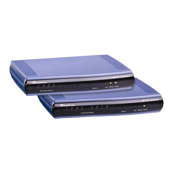
MediaPack SIP User’s Manual 2. MediaPack Physical Description MP-11x Physical Description 2.2.1 MP-11x Front Panel Figure 2-5 illustrates the front layout of the MP-118 (almost identical on MP-114 and MP-112). Table 2-7 lists and describes the front panel LEDs on the MP-11x. MP-11x gateways feature almost identical front panel LEDs;... -
Page 28: Mp-11X Rear Panel
MediaPack SIP 2.2.2 MP-11x Rear Panel Figure 2-6 illustrates the rear layout of the MP-118 (almost identical on MP-114 and MP-112). Table 2-8 lists and describes the rear panel connectors and button on the MP-11x. Figure 2-6: MP-118 Rear Panel Connectors Table 2-8: MP-11x Rear Panel Component Descriptions Item Component Description... -
Page 29: Installing The Mediapack
Open the carton and remove packing materials. Remove the MP-1xx gateway from the carton. Check that there is no equipment damage. Check, retain and process any documents. Notify AudioCodes or your local supplier of any damage or discrepancies. Retain any diskettes or CDs. 3.1.1.1 Package Contents Ensure that in addition to the MP-1xx, the package contains: •... -
Page 30: Mounting The Mp-1Xx
MediaPack SIP 3.1.2 Mounting the MP-1xx The MP-1xx can be mounted on a desktop or on a wall (only MP-10x), or installed in a standard 19-inch rack. Refer to Section 3.1.3 on page for cabling the MP-1xx. 3.1.2.1 Mounting the MP-1xx on a Desktop No brackets are required. -
Page 31: Installing The Mp-124 In A 19-Inch Rack
MediaPack SIP User’s Manual 3. Installing the MediaPack Use the screws found in the devices’ package to attach the short bracket to the side of the device. Remove the two screws on the other side of the device nearest the front panel. Position the long bracket so that the holes in the bracket line up with the two empty screw holes on the device. -
Page 32: Mounting The Mp-10X On A Wall
MediaPack SIP Figure 3-3: MP-124 with Brackets for Rack Installation 3.1.2.4 Mounting the MP-10x on a Wall The MP-10x is mounted on a wall by the addition of two short (equal-length) supplied brackets. The MP-102 with brackets for wall mount is shown in Figure 3-4. -
Page 33: Cabling The Mp-1Xx
MediaPack SIP User’s Manual 3. Installing the MediaPack 3.1.3 Cabling the MP-1xx Verify that you have the cables listed under column ‘Cable’ in Table 3-1 before beginning to cable the MP-1xx according to the column ‘Cabling Procedure’. For detailed information on the MP-1xx rear panel connectors, refer to Section 2.1.2 on page 25. -
Page 34: Figure 3-6: Rj-11 Phone Connector Pinout
MediaPack SIP Figure 3-6: RJ-11 Phone Connector Pinout RJ-11 Connector and Pinout 1 2 3 4 Not connected Ring Not connected Figure 3-7: 50-pin Telco Connector (MP-124/FXS only) Pin Numbers Figure 3-8: MP-124 in a 19-inch Rack with MDF Adaptor 19-inch Rack FRONT INPUT 24 line cords... -
Page 35: Connecting The Mp-1Xx Rs-232 Port To Your Pc
MediaPack SIP User’s Manual 3. Installing the MediaPack Table 3-2: Pin Allocation in the 50-pin Telco Connector Phone Channel Connector Pins Phone Channel Connector Pins 1/26 13/38 2/27 14/39 3/28 15/40 4/29 16/41 5/30 17/42 6/31 18/43 7/32 19/44 8/33 20/45 9/34 21/46... -
Page 36: Figure 3-10: Lifeline Splitter Pinout & Rj-11 Connector For Mp-10X/Fxs
MediaPack SIP Figure 3-10: Lifeline Splitter Pinout & RJ-11 Connector for MP-10x/FXS 1 2 3 4 Lifeline Tip Ring Lifeline Ring To cable the MP-10x/FXS Lifeline phone, take these 3 steps: Connect the Lifeline Splitter to port 4 (on the MP-104/FXS or MP-108/FXS) or to port 2 (on the MP-102/FXS). -
Page 37: Table 3-3: Mp-104/Fxs Lifeline Setup Component Descriptions
MediaPack SIP User’s Manual 3. Installing the MediaPack Table 3-3: MP-104/FXS Lifeline Setup Component Descriptions Item # Component Description B: To PSTN wall port. Phone to Port 1. Lifeline to Port 4. PSTN to Splitter (B). Phone to Port 1. Lifeline phone to Splitter (A). -
Page 38: Installing The Mp-11X
Open the carton and remove the packing materials. Remove the MP-11x gateway from the carton. Check that there is no equipment damage. Check, retain and process any documents. Notify AudioCodes or your local supplier of any damage or discrepancies. Retain any diskettes or CDs. 3.2.2 Package Contents Ensure that in addition to the MP-11x, the package contains: •... -
Page 39: 19-Inch Rack Installation Package
MediaPack SIP User’s Manual 3. Installing the MediaPack 3.2.3 19-inch Rack Installation Package Additional option is available for installing the MP-11x in a 19-inch rack. The 19-inch rack installation package contains a single shelf (shown in Figure 3-12 below) and eight shelf-to- device screws. -
Page 40: Mounting The Mp-11X On A Desktop
Installing the MP-11x in a 19-inch Rack The MP-11x is installed in a standard 19-inch rack by placing it on a shelf preinstalled in the rack. This shelf can be ordered separately from AudioCodes. Figure 3-14: MP-11x Rack Mount Table 3-5: MP-11x Rack Mount... -
Page 41: Cabling The Mp-11X
MediaPack SIP User’s Manual 3. Installing the MediaPack 3.2.5 Cabling the MP-11x Cable your MP-11x according to each section of Table 3-6. For detailed information on the MP- 11x rear panel connectors, refer to Table 2-8 on page 28. Table 3-6: Cables and Cabling Procedure Cable Cabling Procedure Connect the Ethernet connection on the MP-11x directly to the network using a... -
Page 42: Cabling The Mp-11X Lifeline
MediaPack SIP 3.2.5.2 Cabling the MP-11x Lifeline The Lifeline (connected to port #1) provides a wired analog POTS phone connection to any PSTN or PBX FXS port when there is no power, or the when network connection fails. Users can therefore use the Lifeline phone even when the MP-11x is not powered on or not connected to the network. -
Page 43: Getting Started
227). • The embedded Command Line Interface (refer to Section on page 223). • AudioCodes’ Element Management System (EMS) (refer to Section 15.9 on page and to AudioCodes’ EMS User’s Manual or EMS Product Description). To upgrade the MediaPack (load new software or configuration files onto the gateway) use the Software Upgrade wizard, available through the Web Interface (refer to Section 5.8.1... -
Page 44: Assigning An Ip Address Using Http
MediaPack SIP 4.2.1 Assigning an IP Address Using HTTP To assign an IP address using HTTP, take these 8 steps: Disconnect the MediaPack from the network and reconnect it to your PC using one of the following two methods: Use a standard Ethernet cable to connect the network interface on your PC to a port on a network hub / switch. -
Page 45: Configure The Mediapack Basic Parameters
MediaPack SIP User’s Manual 4. Getting Started Add client configuration for the MediaPack, refer to Section B.11.1 on page 263. Use the reset button to physically reset the gateway causing it to use BootP; the MediaPack changes its network parameters to the values provided by the BootP. Configure the MediaPack Basic Parameters To configure the MediaPack basic parameters use the Embedded Web Server’s ‘Quick Setup’... - Page 46 MediaPack SIP ‘Registration Time’ seconds; The MediaPack sends a REGISTER request according to the ‘Authentication Mode’ parameter. For detailed information on the parameters ‘Registration Time’ and ‘Authentication Mode’, refer to Table 5-2 on page Select the coder (i.e., vocoder) that best suits your VoIP system requirements. The default coder is: G.7231 30 msec.
-
Page 47: Configuring The Mediapack
MediaPack SIP User’s Manual 5. Configuring the MediaPack Configuring the MediaPack The Embedded Web Server is used both for gateway configuration, including loading of configuration files, and for run-time monitoring. The Embedded Web Server can be accessed from a standard Web browser, such as Microsoft™ Internet Explorer, Netscape™ Navigator, etc. Specifically, users can employ this facility to set up the gateway configuration parameters. -
Page 48: Limiting The Embedded Web Server To Read-Only Mode
MediaPack SIP The first time a browser request is made, the user is requested to provide his Administrator or Monitoring username and password to obtain access. Subsequent requests are negotiated by the browser on behalf of the user, so that the user doesn’t have to re-enter the username and password for each request, but the request is still authenticated (the Embedded Web Server uses the MD5 authentication method supported by the HTTP 1.1 protocol). -
Page 49: Using Internet Explorer To Access The Embedded Web Server
MediaPack SIP User’s Manual 5. Configuring the MediaPack 5.3.1 Using Internet Explorer to Access the Embedded Web Server Internet explorer’s security settings may block access to the gateway’s Web browser if they’re configured incorrectly. In this case, the following message is displayed: Unauthorized Correct authorization is required for this area. -
Page 50: Main Menu Bar
Submenu bar - appears on the top of screens and contains submenu options. • Main action frame - the main area of the screen in which information is viewed and configured. • Corporate logo – AudioCodes’ corporate logo. For information on how to remove this logo Section 10.5 on page 206. •... -
Page 51: Protocol Management
MediaPack SIP User’s Manual 5. Configuring the MediaPack Protocol Management Use this menu to configure the gateway’s SIP parameters and tables. Those parameters contained within square brackets are the names used to Note: configure the parameters via the ini file. 5.5.1 Protocol Definition Parameters Use this submenu to configure the gateway’s specific SIP protocol parameters. -
Page 52: Table 5-1: Protocol Definition, General Parameters (Continues On Pages 52 To 55)
MediaPack SIP Configure the general parameters under Protocol Definition according to Table 5-1. Click the Submit button to save your changes. To save the changes so they are available after a power fail, refer to Section on page 161. Table 5-1: Protocol Definition, General Parameters (continues on pages 52 to 55) Parameter Description PRACK Mode... - Page 53 MediaPack SIP User’s Manual 5. Configuring the MediaPack Table 5-1: Protocol Definition, General Parameters (continues on pages 52 to 55) Parameter Description Asserted Identity Mode Disable [0] = None (default). Adding PAsserted Identity [1]. [AssertedIdMode] Adding PPreferred Identity [2]. The Asserted ID mode defines the header that is used in the generated INVITE request. The header also depends on the calling Privacy: allowed or restricted.
- Page 54 MediaPack SIP Table 5-1: Protocol Definition, General Parameters (continues on pages 52 to 55) Parameter Description Enable SIPS Enables secured SIP (SIPS) connections over multiple hops (MP-11x only). Disable [0] (default). [EnableSIPS] Enable [1]. When SIPTransportType = 2 (TLS) and EnableSIPS is disabled, TLS is used for the next network hop only.
- Page 55 MediaPack SIP User’s Manual 5. Configuring the MediaPack Table 5-1: Protocol Definition, General Parameters (continues on pages 52 to 55) Parameter Description Retransmission Parameters SIP T1 Retransmission Timer The time interval (in msec) between the first transmission of a SIP message and the first [msec] retransmission of the same message.
-
Page 56: Proxy & Registration Parameters
MediaPack SIP 5.5.1.2 Proxy & Registration Parameters Use this screen to configure parameters that are associated with Proxy and Registration. To configure the Proxy & Registration parameters, take these 4 steps: Open the ‘Proxy & Registration’ parameters screen (Protocol Management menu > Protocol Definition submenu >... -
Page 57: Table 5-2: Proxy & Registration Parameters (Continues On Pages 57 To 60)
MediaPack SIP User’s Manual 5. Configuring the MediaPack Table 5-2: Proxy & Registration Parameters (continues on pages 57 to 60) Parameter Description Enable Proxy Don’t Use Proxy [0] = Proxy isn’t used, the internal routing table is used instead (default). [IsProxyUsed] Use Proxy [1] = Proxy is used. - Page 58 MediaPack SIP Table 5-2: Proxy & Registration Parameters (continues on pages 57 to 60) Parameter Description Third Redundant Proxy IP IP addresses of the third redundant Proxy you are using. Address Enter the IP address as FQDN or in dotted format notation (for example 192.10.1.255). You can also specify the selected port in the format: <IP Address>:<port>.
- Page 59 MediaPack SIP User’s Manual 5. Configuring the MediaPack Table 5-2: Proxy & Registration Parameters (continues on pages 57 to 60) Parameter Description Registrar IP Address IP address and optionally port number of Registrar server. Enter the IP address in dotted format notation, for example 201.10.8.1:<5080>. [RegistrarIP] Note 1: If not specified, the REGISTER request is sent to the primary Proxy server (refer to ‘Proxy IP address’...
- Page 60 MediaPack SIP Table 5-2: Proxy & Registration Parameters (continues on pages 57 to 60) Parameter Description Send All INVITE to Proxy No [0] = INVITE messages, generated as a result of Transfer or Redirect, are sent directly to the URL (according to the refer-to header in the REFER message or contact [SendInviteToProxy] header in 30x response) (default).
-
Page 61: Coders
MediaPack SIP User’s Manual 5. Configuring the MediaPack 5.5.1.3 Coders From the Coders screen you can configure the first to fifth preferred coders (and their corresponding ptimes) for the gateway. The first coder is the highest priority coder and is used by the gateway whenever possible. -
Page 62: Table 5-3: Ini File Coder Parameter
MediaPack SIP Table 5-3: ini File Coder Parameter Parameter Description Enter the coders in the format: CoderName=<Coder>,<ptime>. CoderName For example: CoderName = g711Alaw64k,20 CoderName = g711Ulaw64k,40 CoderName = g7231,90 Note 1: This parameter (CoderName) can appear up to 10 times. Note 2: The coder name is case-sensitive. -
Page 63: Dtmf & Dialing Parameters
MediaPack SIP User’s Manual 5. Configuring the MediaPack 5.5.1.4 DTMF & Dialing Parameters Use this screen to configure parameters that are associated with DTMF and dialing. To configure the dialing parameters, take these 4 steps: Open the ‘DTMF & Dialing’ screen (Protocol Management menu > Protocol Definition submenu >... - Page 64 MediaPack SIP Table 5-4: DTMF & Dialing Parameters (continues on pages 63 to 65) Parameter Description Use Out-of-Band DTMF Use out-of-band signaling to relay DTMF digits. [0] = DTMF digits are sent in-band (default). [IsDTMFUsed] [1] = DTMF digits are sent out-of-band according to the parameter ‘Out-of-band DTMF format’.
- Page 65 MediaPack SIP User’s Manual 5. Configuring the MediaPack Table 5-4: DTMF & Dialing Parameters (continues on pages 63 to 65) Parameter Description Digit Mapping Rules Digit map pattern. If the digit string (dialed number) has matched one of the patterns in the digit map, the gateway stops collecting digits and starts to establish a call with the [DigitMapping] collected number...
-
Page 66: Configuring The Advanced Parameters
MediaPack SIP 5.5.2 Configuring the Advanced Parameters Use this submenu to configure the gateway’s advanced control protocol parameters. 5.5.2.1 General Parameters Use this screen to configure general control protocol parameters. To configure the general parameters under Advanced Parameters, take these 4 steps: Open the ‘General Parameters’... -
Page 67: Table 5-5: Advanced Parameters, General Parameters (Continues On Pages 67 To 70)
MediaPack SIP User’s Manual 5. Configuring the MediaPack Configure the general parameters under ‘Advanced Parameters’ according to Table 5-5. Click the Submit button to save your changes. To save the changes so they are available after a power fail, refer to Section on page 161. - Page 68 MediaPack SIP Table 5-5: Advanced Parameters, General Parameters (continues on pages 67 to 70) Parameter Description Enable DID Wink Disable [0] = DID is disabled (default). Enable [1] = Enable DID. [EnableDIDWink] If enabled, the MediaPack can be used for connection to EIA/TIA-464B DID Loop Start lines.
- Page 69 MediaPack SIP User’s Manual 5. Configuring the MediaPack Table 5-5: Advanced Parameters, General Parameters (continues on pages 67 to 70) Parameter Description Silence Detection Method Silence detection method. None [0] = Silence detection option is disabled. [FarEndDisconnectSilenceM Packets Count [1] = According to packet count. ethod] Voice/Energy Detectors [2] = According to energy and voice detectors (default).
- Page 70 MediaPack SIP Table 5-5: Advanced Parameters, General Parameters (continues on pages 67 to 70) Parameter Description Max Number of Active Calls Defines the maximum number of calls that the gateway can have active at the same time. If the maximum number of calls is reached, new calls are not established. [MaxActiveCalls] The default value is max available channels (no restriction on the maximum number of calls).
-
Page 71: Supplementary Services
MediaPack SIP User’s Manual 5. Configuring the MediaPack 5.5.2.2 Supplementary Services Use this screen to configure parameters that are associated with supplementary services. For detailed information on the supplementary services, refer to Section on page 169. To configure the supplementary services’ parameters, take these 4 steps: Open the ‘Supplementary Services’... -
Page 72: Table 5-6: Supplementary Services Parameters (Continues On Pages 72 To 74)
MediaPack SIP Table 5-6: Supplementary Services Parameters (continues on pages 72 to 74) Parameter Description Enable Hold No [0] = Disable the Hold service (default). Yes [1] = Enable the Hold service. [EnableHold] If the Hold service is enabled, a user can activate Hold (or Unhold) using the hook-flash. On receiving a Hold request, the remote party is put on-hold and hears the hold tone. -
Page 73: Message Waiting Indication
MediaPack SIP User’s Manual 5. Configuring the MediaPack Table 5-6: Supplementary Services Parameters (continues on pages 72 to 74) Parameter Description Enable Caller ID No [0] = Disable the Caller ID service (default). Yes [1] = Enable the Caller ID service. [EnableCallerID] If the Caller ID service is enabled, then, for FXS gateways, calling number and Display text are sent to gateway port. -
Page 74: Keypad Features
MediaPack SIP Table 5-6: Supplementary Services Parameters (continues on pages 72 to 74) Parameter Description Stutter Tone Duration Duration (in msec) of the played stutter dial tone that indicates waiting message(s). The default is 2000 (2 seconds). The range is 1000 to 60000. [StutterToneDuration] The Stutter tone is played (instead of a regular Dial tone) when a MWI is received. -
Page 75: Table 5-7: Keypad Features Parameters
MediaPack SIP User’s Manual 5. Configuring the MediaPack To save the changes so they are available after a power fail, refer to Section on page 161. The method used by the gateway to collect dialed numbers is identical to the Note: method used during a regular call (i.e., max digits, interdigit timeout, digit map, etc.). -
Page 76: Configuring The Number Manipulation Tables
MediaPack SIP 5.5.3 Configuring the Number Manipulation Tables The VoIP gateway provides four Number Manipulation tables for incoming and outgoing calls. These tables are used to modify the destination and source telephone numbers so that the calls can be routed correctly. The Manipulation Tables are: •... -
Page 77: Table 5-8: Number Manipulation Parameters
MediaPack SIP User’s Manual 5. Configuring the MediaPack Click the Submit button to save your changes. To save the changes so they are available after a power fail, refer to Section on page 161. Table 5-8: Number Manipulation Parameters Parameter Description Destination Prefix Each entry in the Destination Prefix fields represents a destination telephone number... -
Page 78: Table 5-9: Number Manipulation Ini File Parameters (Continues On Pages 78 To 79)
MediaPack SIP Table 5-9: Number Manipulation ini File Parameters (continues on pages 78 to 79) Parameter Description Manipulates the destination number for Tel to IP calls. NumberMapTel2IP NumberMapTel2IP = a,b,c,d,e,f,g = Destination number prefix = Number of stripped digits from the left, or (if brackets are used) from the right. A combination of both options is allowed. -
Page 79: Dialing Plan Notation
MediaPack SIP User’s Manual 5. Configuring the MediaPack Parameter Description SourceNumberMapTel2IP = a,b,c,d,e,f,g,h SourceNumberMapTel2IP = Source number prefix = Number of stripped digits from the left, or (if in brackets are used) from right. A combination of both options is allowed. = String to add as prefix, or (if in brackets are used) as suffix. - Page 80 MediaPack SIP For example: • [5551200-5551300]# represents all numbers from 5551200 to 5551300 • [2,3,4]xxx# represents four-digit numbers that start with 2, 3 or 4 • 54324 represents any number that starts with 54324 • 54324xx# represents a 7 digit number that starts with 54324 •...
-
Page 81: Configuring The Routing Tables
MediaPack SIP User’s Manual 5. Configuring the MediaPack 5.5.4 Configuring the Routing Tables Use this submenu to configure the gateway’s IP Tel and Tel IP routing tables and their associated parameters. 5.5.4.1 General Parameters Use this screen to configure the gateway’s IP Tel and Tel IP routing parameters. To configure the general parameters under Routing Tables, take these 4 steps: Open the ‘General Parameters’... -
Page 82: Operation
MediaPack SIP Table 5-10: Routing Tables, General Parameters (continues on pages 81 to 82) Parameter Description IP to Tel Remove Routing No [0] = Don't remove prefix (default) Table Prefix Yes [1] = Remove the prefix (defined in the IP to Hunt Group Routing table) from a telephone number for an IP Tel call, before forwarding it to Tel. -
Page 83: Tel To Ip Routing Table
MediaPack SIP User’s Manual 5. Configuring the MediaPack 5.5.4.2 Tel to IP Routing Table The Tel to IP Routing Table is used to route incoming Tel calls to IP addresses. This routing table associates a called / calling telephone number’s prefixes with a destination IP address or with an FQDN (Fully Qualified Domain Name). -
Page 84: Figure 5-12: Tel To Ip Routing Table Screen
MediaPack SIP Tel to IP routing can be performed either before or after applying the number Tip: manipulation rules. To control when number manipulation is done, set the Tel to IP Routing Mode parameter (described in Table 5-11). To configure the Tel to IP Routing table, take these 6 steps: Open the ‘Tel to IP Routing’... - Page 85 MediaPack SIP User’s Manual 5. Configuring the MediaPack Table 5-11: Tel to IP Routing Table Parameter Description Destination IP Address In each of the IP Address fields, enter the IP address (and optionally port number) that is assigned to these prefixes. Domain names, such as domain.com, can be used instead of IP addresses.
-
Page 86: Ip To Hunt Group Routing
MediaPack SIP 5.5.4.3 IP to Hunt Group Routing The IP to Hunt Group Routing Table is used to route incoming IP calls to groups of channels called hunt groups. Calls are assigned to hunt groups according to any combination of the following three options (or using each independently): •... -
Page 87: Table 5-12: Ip To Hunt Group Routing Table
MediaPack SIP User’s Manual 5. Configuring the MediaPack In the ‘IP to Tel Routing Mode’ field, select the IP to Tel routing mode (refer to Table 5-12). In the ‘Routing Index’ drop-down list, select the range of entries that you want to edit (up to 24 entries can be configured). -
Page 88: Internal Dns Table
MediaPack SIP 5.5.4.4 Internal DNS Table The internal DNS table, similar to a DNS resolution, translates hostnames into IP addresses. This table is used when hostname translation is required (e.g., ‘Tel to IP Routing’ table). Two different IP addresses can be assigned to the same hostname. If the hostname isn’t found in this table, the gateway communicates with an external DNS server. -
Page 89: Reasons For Alternative Routing
MediaPack SIP User’s Manual 5. Configuring the MediaPack 5.5.4.5 Reasons for Alternative Routing The Reasons for Alternative Routing screen includes two tables (Tel IP and IP Tel). Each table enables you to define up to 4 different release reasons. If a call is released as a result of one of these reasons, the gateway tries to find an alternative route to that call. -
Page 90: Table 5-14: Reasons For Alternative Routing Ini File Parameter
MediaPack SIP Table 5-14: Reasons for Alternative Routing ini File Parameter Parameter Name in ini File Parameter Format AltRouteCauseTel2IP = <SIP Call failure reason from IP> AltRouteCauseTel2IP For example: AltRouteCauseTel2IP = 408 (Response timeout). AltRouteCauseTel2IP = 486 (User is busy). Note: This parameter can appear up to 4 times. -
Page 91: Configuring The Profile Definitions
MediaPack SIP User’s Manual 5. Configuring the MediaPack 5.5.5 Configuring the Profile Definitions Utilizing the Profiles feature, the MediaPack provides high-level adaptation when connected to a variety of equipment (from both Tel and IP sides) and protocols, each of which require a different system behavior. -
Page 92: Table 5-15: Ini File Coder Group Parameters
MediaPack SIP many coder payloads are combined into one RTP (voice) packet. Note 1: The ptime packetization period depends on the selected coder name. Note 2: If not specified, the ptime gets a default value. Note 3: The ptime specifies the maximum packetization time the gateway can receive. Repeat steps 3 and 4 for the second to fifth coders (optional). -
Page 93: Tel Profile Settings
MediaPack SIP User’s Manual 5. Configuring the MediaPack 5.5.5.2 Tel Profile Settings Use the Tel Profile Settings screen to define up to four different Tel Profiles. These Profiles are used in the ‘Endpoint Phone Number’ table to associate different Profiles to gateway’s endpoints, thereby applying different behavior to different MediaPack ports. -
Page 94: Table 5-16: Ini File Tel Profile Settings
MediaPack SIP Configure the Profile’s parameters according to your requirements. For detailed information on each parameter, refer to the description of the screen in which it is configured as an individual parameter. In the ‘Coder Group’ drop-down list, select the coder group you want to assign to that Profile. You can select the gateway’s default coders (refer to Section 5.5.1.3 on page 61) or one of... -
Page 95: Ip Profile Settings
MediaPack SIP User’s Manual 5. Configuring the MediaPack 5.5.5.3 IP Profile Settings Use the IP Profile Settings screen to define up to four different IP Profiles. These Profiles are used in the Tel to IP and IP to Hunt Group Routing tables to associate different Profiles to routing rules. -
Page 96: Table 5-17: Ini File Ip Profile Settings
MediaPack SIP the coder groups you defined in the Coder Group Settings screen (refer to Section 5.5.5.1 page 91). Repeat steps 2 to 6 for the second to fifth IP Profiles (optional). Click the Submit button to save your changes. To save the changes so they are available after a power fail, refer to Section on page 161. -
Page 97: Configuring The Endpoint Phone Numbers
MediaPack SIP User’s Manual 5. Configuring the MediaPack 5.5.6 Configuring the Endpoint Phone Numbers From the Endpoint Phone Numbers screen you can enable and assign telephone numbers, hunt groups (optional) and profiles to the VoIP gateway ports. To configure the Endpoint Phone Numbers table, take these 4 steps: Open the ‘Endpoint Phone Numbers Table’... - Page 98 MediaPack SIP Table 5-18: Endpoint Phone Numbers Table Parameter Description Hunt Group ID In each of the Hunt Group ID fields, enter the hunt group ID (1-99) assigned to the channel(s). The same hunt group ID can be used for more than one channel and in more than one field.
-
Page 99: Configuring The Hunt Group Settings
MediaPack SIP User’s Manual 5. Configuring the MediaPack 5.5.7 Configuring the Hunt Group Settings The Hunt Group Settings Table is used to determine the method in which new calls are assigned to channels within each hunt group. If such a rule doesn’t exist (for a specific hunt group), the global rule, defined by the Channel Select Mode parameter (Protocol Definition >... -
Page 100: Table 5-19: Channel Select Modes
MediaPack SIP Table 5-19: Channel Select Modes Mode Description By phone number Select the gateway port according to the called number (refer to the note below). Cyclic Ascending Select the next available channel in ascending cycle order. Always select the next higher channel number in the hunt group. -
Page 101: Configuring The Endpoint Settings
MediaPack SIP User’s Manual 5. Configuring the MediaPack 5.5.8 Configuring the Endpoint Settings The Endpoint Settings screens enable you to configure port-specific parameters. 5.5.8.1 Authentication The Authentication Table (normally used with FXS gateways) defines a username and password combination for authentication for each MediaPack port. The ‘Authentication Mode’... -
Page 102: Automatic Dialing
MediaPack SIP 5.5.8.2 Automatic Dialing Use the Automatic Dialing Table to define telephone numbers that are automatically dialed when a specific port is used. To configure the Automatic Dialing table, take these 6 steps: Open the ‘Automatic Dialing’ screen (Protocol Management menu > Endpoint Settings submenu >... -
Page 103: Caller Id
MediaPack SIP User’s Manual 5. Configuring the MediaPack 5.5.8.3 Caller ID Use the Caller Display Information screen to send (to IP) Caller ID information when a call is made using the VoIP gateway (relevant to both FXS and FXO). The person receiving the call can use this information for caller identification. -
Page 104: Generate Caller Id To Tel
MediaPack SIP Table 5-22: Caller ID ini File Parameter Parameter Name in ini File Parameter Format CallerDisplayInfo<channel> = <Caller ID string>,<Restriction> CallerDisplayInfoX 0 = Not restricted (default). 1 = Restricted. For example: CallerDisplayInfo0 = Susan C.,0 CallerDisplayInfo2 = Mark M.,1 Note 1: The numbering of channels starts with 0. -
Page 105: Call Forward
MediaPack SIP User’s Manual 5. Configuring the MediaPack To save the changes so they are available after a power fail, refer to Section on page 161. Table 5-23: Authentication ini File Parameter Parameter Name in ini File Parameter Format EnableCallerID_<Port> = <Caller ID> EnableCallerID_X Caller ID: = Disabled (default). -
Page 106: Table 5-24: Call Forward Table
MediaPack SIP Table 5-24: Call Forward Table Parameter Description Forward Type Not in use [0] = Don’t forward incoming calls (default). On Busy [1] = Forward incoming calls when the gateway port is busy. Immediate [2] = Forward any incoming call to the Phone number specified. No reply [3] = Forward incoming calls that are not answered with the time specified in the ‘Time for No Reply Forward’... -
Page 107: Configuring The Fxo Parameters
MediaPack SIP User’s Manual 5. Configuring the MediaPack 5.5.9 Configuring the FXO Parameters Use this screen to configure the gateway’s specific FXO parameters. To configure the FXO parameters, take these 4 steps: Open the ‘FXO Settings’ screen (Protocol Management menu > FXO Settings > FXO Settings option);... - Page 108 MediaPack SIP Table 5-25: FXO Parameters (continues on pages 107 to 109) Parameter Description Waiting For Dial Tone No [0] = Don’t wait for dial tone. Yes [1] = Wait for dial tone (default). [IsWaitForDialTone] Used for IP MediaPack/FXO gateways, when ‘One Stage Dialing’ is enabled. If ‘wait for dial tone’...
-
Page 109: 5.5.10 Configuring The Voice Mail (Vm) Parameters
MediaPack SIP User’s Manual 5. Configuring the MediaPack Table 5-25: FXO Parameters (continues on pages 107 to 109) Parameter Description DisconnectOnBusyTone No [0] = Call isn’t released (FXO gateway). [Disconnect on Busy Tone] Yes [1] = Call is released (on FXO gateways) if busy or reorder (fast busy) tones are detected on the gateway’s FXO port (default). -
Page 110: Table 5-26: Voice Mail Parameters
MediaPack SIP Table 5-26: Voice Mail Parameters Parameter Description General Voice Mail Interface Enables the VM application on the MediaPack and determines the communication method used between the PBX and the gateway. [VoiceMailInterface] None [0] (default). DTMF [1]. SMDI [2]. Wait For Dial Time N/A. -
Page 111: 5.5.11 Protocol Management Ini File Parameters
MediaPack SIP User’s Manual 5. Configuring the MediaPack 5.5.11 Protocol Management ini File Parameters Table 5-27 describes the SIP Protocol Management parameters that can only be configured via the ini file. Table 5-27: Protocol Management, ini File Parameters (continues on pages 111 to 113) ini File Parameter Valid Range and Description Name... - Page 112 MediaPack SIP Table 5-27: Protocol Management, ini File Parameters (continues on pages 111 to 113) ini File Parameter Valid Range and Description Name Defines the metering tone (12 kHz or 16 kHz) that is detected by FXO gateways and MeteringType generated by FXS gateways.
- Page 113 MediaPack SIP User’s Manual 5. Configuring the MediaPack Table 5-27: Protocol Management, ini File Parameters (continues on pages 111 to 113) ini File Parameter Valid Range and Description Name Serial parameters (applicable only to the VM SMDI application) Determines the value of the RS-232 baud rate. SerialBaudRate The valid range is: any value.
-
Page 114: Advanced Configuration
MediaPack SIP Advanced Configuration Use this menu to set the gateway’s advanced configuration parameters (for advanced users only). Those parameters contained within square brackets are the names used to Note: configure the parameters via the ini file. 5.6.1 Configuring the Network Settings From the Network Settings you can: •... -
Page 115: Table 5-28: Network Settings, Ip Settings Parameters (Continues On Pages 128 To 131)
MediaPack SIP User’s Manual 5. Configuring the MediaPack To save the changes so they are available after a power fail, refer to Section on page 161. Table 5-28: Network Settings, IP Settings Parameters (continues on pages 128 to 131) Parameter Description IP Networking Mode Enables / disables the Multiple IPs mechanism. - Page 116 MediaPack SIP Table 5-28: Network Settings, IP Settings Parameters (continues on pages 128 to 131) Parameter Description DHCP Settings Enable DHCP Disable [0] = Disable DHCP support on the gateway (default). Enable [1] = Enable DHCP support on the gateway. [DHCPEnable] After the gateway is powered up, it attempts to communicate with a BootP server.
-
Page 117: Configuring The Application Settings
MediaPack SIP User’s Manual 5. Configuring the MediaPack 5.6.1.2 Configuring the Application Settings To configure the Application Settings parameters, take these 4 steps: Open the ‘Application Settings’ screen (Advanced Configuration menu > Network Settings > Application Settings option); the ‘Application Settings’ screen is displayed. Figure 5-29: Application Settings Screen Configure the Application Settings according to Table... -
Page 118: Syslog Servers
MediaPack SIP Table 5-29: Network Settings, Application Settings Parameters Parameter Description Syslog Settings Syslog Server IP address IP address (in dotted format notation) of the computer you are using to run the Syslog Server. [SyslogServerIP] The Syslog Server is an application designed to collect the logs and error messages generated by the VoIP gateway. -
Page 119: Configuring The Snmp Managers Table
MediaPack SIP User’s Manual 5. Configuring the MediaPack 5.6.1.3 Configuring the SNMP Managers Table The SNMP Managers table allows you to configure the attributes of up to five SNMP managers. To configure the SNMP Managers Table, take these 6 steps: Access the ‘Application Settings’... -
Page 120: Configuring The Web And Telnet Access List
MediaPack SIP 5.6.1.4 Configuring the Web and Telnet Access List Use this screen to define up to ten IP addresses that are permitted to access the gateway’s Web and Telnet interfaces. Access from an undefined IP address is denied. This security feature is inactive (the gateway can be accessed from any IP address) when the table is empty.
Need help?
Do you have a question about the MediaPack MP-108 and is the answer not in the manual?
Questions and answers