Table of Contents
Advertisement
Quick Links
Advertisement
Table of Contents

Related Manuals for Canon DADF-Q1


Summary of Contents for Canon DADF-Q1
- Page 1 Service Manual Feeder DADF-Q1 Aug 24 2007...
- Page 3 Canon will release technical information as the need arises. In the event of major changes in the contents of this manual over a long or short period, Canon will issue a new edition of this manual.
-
Page 4: Symbols Used
Introduction Symbols Used This documentation uses the following symbols to indicate special information: Symbol Description Indicates an item of a non-specific nature, possibly classified as Note, Caution, or Warning. Indicates an item requiring care to avoid electric shocks. Indicates an item requiring care to avoid combustion (fire). Indicates an item prohibiting disassembly to avoid electric shocks or problems. - Page 5 Introduction The following rules apply throughout this Service Manual: 1. Each chapter contains sections explaining the purpose of specific functions and the relationship between electrical and mechanical systems with refer- ence to the timing of operation. In the diagrams, represents the path of mechanical drive; where a signal name accompanies the symbol , the arrow indicates the direction of the electric signal.
-
Page 7: Table Of Contents
Contents Contents Chapter 1 Specifications 1.1 Product Specifications ..........................1- 1 1.1.1 ADF Specifications ..............................1- 1 1.2 Names of Parts ............................1- 2 1.2.1 External View................................1- 2 1.2.2 Cross Section ................................1- 3 1.3 Using the Machine ............................1- 3 1.3.1 Original Set Indicator ............................... 1- 3 Chapter 2 Functions 2.1 Basic Construction............................2- 1 2.1.1 Overview of Electrical Circuit........................... - Page 8 Contents 2.7.3 Alarm Code ................................2- 51 2.8 Power Supply ............................2- 51 2.8.1 Overview ................................2- 51 Chapter 3 Parts Replacement Procedure 3.1 Removing from the Host Machine ......................3- 1 3.1.1 Feeder..................................3- 1 3.1.1.1 Disconnecting the DADF................................3- 1 3.2 External Covers ............................3- 1 3.2.1 External Covers ...............................3- 1 3.2.1.1 External Covers ..................................
- Page 9 Contents 3.4.5 Delivery Roller ............................... 3- 18 3.4.5.1 Disconnecting the DADF................................ 3- 18 3.4.5.2 Removing the Front Cover..............................3- 18 3.4.5.3 Removing the Main Cover ..............................3- 18 3.4.5.4 Removing the Delivery Roller ..............................3- 19 3.4.6 Pickup Rollor ................................. 3- 20 3.4.6.1 Removing the Pickup Roller..............................
- Page 10 Contents 4.3.1.4 Correcting the Skew................................4- 14 4.3.1.5 Horizontal Registration Adjustment............................4- 17 4.3.1.6 Original Stop Position Adjustment ............................4- 19 4.3.1.7 Stream Reading Speed Adjustment............................4- 21 4.3.2 Adjustment at Time of Parts Replacement ......................4- 21 4.3.2.1 Outline....................................4- 21 4.3.2.2 Replacing the EEPROM ................................
-
Page 11: Chapter 1 Specifications
Chapter 1 Specifications... - Page 13 Contents Contents 1.1 Product Specifications..............................1-1 1.1.1 ADF Specifications ..................................1-1 1.2 Names of Parts ................................1-2 1.2.1 External View ....................................1-2 1.2.2 Cross Section ....................................1-3 1.3 Using the Machine .................................1-3 1.3.1 Original Set Indicator................................... 1-3...
-
Page 15: Product Specifications
Chapter 1 1.1 Product Specifications 1.1.1 ADF Specifications 0011-1972 T-1-1 Item Description Remarks Original pickup auto Original placement original tray face-up manual feeder face-down: against rear end Original separation top separation Original type Sheet Original weight original tray 50 to 216g/m2 However, if large-size double-sided, 100 g/m2;... -
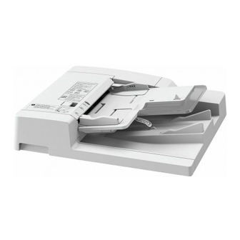
Page 16: Names Of Parts
Chapter 1 Book original supported (mobile hinge assembly; up/down) Tracing paper mode Silent mode stamp Communication with host IP communication 2 machine Power supply 24 VDC, 13 VDC From printer unit by way of reader unit. Weight 21.5 kg (approx.) Not including delivery tray. -
Page 17: Cross Section
Chapter 1 1.2.2 Cross Section 0011-1993 [1] [2] [3] [4] [5] [6] [7] [8] [10] [11] [12] [18] [17] [16] [15] [14] [13] [23] [22] [21] [20] [19] F-1-2 Reversing roller B member [13] Delivery roller B member Reversing roller B [14] Delivery roller Reversing flapper... -
Page 19: Chapter 2 Functions
Chapter 2 Functions... - Page 21 Contents Contents 2.1 Basic Construction .................................2-1 2.1.1 Overview of Electrical Circuit ..............................2-1 2.1.2 Inputs to ADF Controller PCB ..............................2-2 2.1.3 Outputs from ADF Controller PCB ............................. 2-4 2.2 Basic Operation................................2-4 2.2.1 Outline......................................2-4 2.2.2 Outline......................................2-6 2.2.3 CW Pickup/Delivery ..................................2-7 2.2.4 Pre-Reversal/Reversal/Delivery..............................
-
Page 23: Basic Construction
Chapter 2 2.1 Basic Construction 2.1.1 Overview of Electrical Circuit 0011-2223 The machine's electrical mechanisms are controlled by the ADF controller PCB (microcomputer CPU). The CPU interprets signals from sensors and the host ma- chine, and generates appropriate signals to drive such loads as motors and solenoids at such times as programmed in advance. ADF controller PCB Motor (Q1) -
Page 24: Inputs To Adf Controller Pcb
Chapter 2 2.1.2 Inputs to ADF Controller PCB 0011-2225 -Inputs to ADF Controller PCB(1/2) ADF controller PCB J12-3 Pulses according to the PI 1 Belt motor clock rotation speed of the belt BTCLK sensor motor. J12-6 Pulses according to the PI 2 Separation motor rotation speed of the... - Page 25 Chapter 2 -Inputs to ADF Controller PCB(2/2) ADF controller PCB J14-B1 Reference signal for TNSAJ paper detection Reversal sensor When paper is present, '0'. J149 J144 J13-8 Reference signal for Pre-registration RGBSAJ paper detection RGBS roller paper sensor When paper is present, '0'. Reference signal for Post registration RGASAJ...
-
Page 26: Outputs From Adf Controller Pcb
Chapter 2 2.1.3 Outputs from ADF Controller PCB 0011-2226 -Outputs from ADF Controller PCB(1/1) ADF controller PCB +24V J10-3 When '0', Separation clutch the separation clutch CLD* J102 goes on. +24V J9-1 When '0', the solenoid Reversal solenoid SL1D* goes on. +24V J9-3 Stopper plate solenoid... - Page 27 Chapter 2 Diagram of Drive ADF controller PCB PI 2 PI 11 PI 1 PI 5 F-2-5...
-
Page 28: Outline
Chapter 2 Sensor Arrangement ADF controller PCB PI 2 PI 11 PI 1 PI 5 F-2-6 2.2.2 Outline 0011-2233 The DADF operates in either of the following three modes; the DADF operates in response to instructions from the copier, executing appropriate modes to suit the copier's operations. -
Page 29: Cw Pickup/Delivery
Chapter 2 2.2.3 CW Pickup/Delivery 0011-2234 The following is an outline of the flow of originals. Pickup F-2-7 Scan F-2-8 Delivery F-2-9 2.2.4 Pre-Reversal/Reversal/Delivery 0011-2235 The following is an outline of the flow of originals: Picking up Pre-reversing Feeding Copying the 1st side Moving To next page... -
Page 30: Manual Feeder Pickup/Delivery
Chapter 2 From previous page Reversing Copying the 2nd side Delivering F-2-11 2.2.5 Manual Feeder Pickup/Delivery 0011-2237 The following is an outline of the flow of originals: Picking up Stopping Switching back Copying Delivering F-2-12... -
Page 31: Document Detection
Chapter 2 2.3 Document Detection 2.3.1 Outline 0011-2238 The DADF is equipped with the following five types of mechanisms of detection: T-2-2 Item Description Sensor used (notation) Presence/absence of an original Identifies the presence/absence of an original on the original tray. Original sensor (S6) Original size 1 Identifies the size of the original placed in the original tray (as to being... -
Page 32: Original Size Detection 1
Chapter 2 ADF controller PCB (light-emitting side) (light-receiving side) When an original is detected When no original is detected ADF controller PCB ADF controller PCB (light-emitting side) (light-emitting side) Light is blocked. (light-receiving side) (light-receiving side) Original F-2-14 2.3.3 Original Size Detection 1 0011-2242 In original size detection 1, the original trailing edge sensor is used (S7), which is designed to identify the original in the original tray as being small-size or large- size. -
Page 33: Original Size Detection 2
Chapter 2 ADF controller PCB If the original is identified If the original is identified as being large-size as being small-size ADF controller PCB ADF controller PCB Reflected light detected Reflected light absent Original Original F-2-15 2.3.4 Original Size Detection 2 0011-2243 a. - Page 34 Chapter 2 Default size SSW0 SSW1 SSW2 SSW3 SSW4 B5, B4 STMT, LTRR, LGL LTR, 279.4X431.8mm (11"X17") The registration roller clock sensor (PI5) is used to measure the length of originals with reference to the revolutions made by the clock plate mounted to the slave roller of the registration roller.
- Page 35 Chapter 2 Inch-Configuration (unit: mm) Default size Original length Original width STMT 120 to 180 213 to 220.9 LTRR 259 to 309 FOOLSCAP 310 to 343 343 to 396 196 to 256 274.4 to 284.4 279.4X431.8 (11"X17") 412 to 472 A size outside of the above ranges will be identified as a non-default size.
-
Page 36: Detecting The Presence/Absence Of An Original In The Manual Feeder
Chapter 2 Slide guide lock F-2-18 Be sure to adjust the slide guide to suit the original size when making copies. Otherwise, the original is likely to move askew. c. Slide Guide Positioning Member The rail of the slide guide is provided with notches to make sure that the slide guide stops to suit a specific default original size. Some of these points representing differing paper sizes, however, are close enough to allow the slide guide to be set at the wrong point. -
Page 37: Document Pickup/Separation
Chapter 2 Manual set sensor (PI12) Sensor flag Original F-2-20 2.4 Document Pickup/Separation 2.4.1 Outline 0011-2327 The pickup roller unit is butted against the original, and the pickup roller is rotated to pick up an original. The pickup roller unit is moved up/down by the pickup motor (M3), and the pickup roller is rotated by the separation motor (M4) and the separation clutch (CL). - Page 38 Chapter 2 T-2-8 Stop position Operation Related sensor (notation) Home position Waits until the next copying operation. Pickup roller home position sensor (PI7) Wait position Waits until the next pickup position Pickup height sensor 1/2 (PI8/9) Pulse control of pickup motor (M3) Pickup position Picks up originals Pickup height sensor 1/2 (PI8/9)
-
Page 39: Switching The Separation Pressure
Chapter 2 F-2-24 When the leading edge of the 1st original reaches the separation sensor (S4), the pickup motor (M3) starts to rotate to move the pickup roller unit from the surface of the stack of originals. The pickup roller unit stops about 6 mm from the surface of the stack of originals. Separation sensor (S4) F-2-25 When the trailing edge of the 1st original moves past the point of contact [1] of the pickup roller, the pickup roller unit once again moves down to the surface of... -
Page 40: Separation Sensor (S4) And Skew Sensor (S5)
Chapter 2 High F-2-27 2.4.4 Separation Sensor (S4) and Skew Sensor (S5) 0011-2331 The paper path is equipped with a separation sensor (S4) and a skew sensor (S5) to monitor the movement of originals for the following: T-2-9 Item Sensor used (notation) Alarm Separation fault (delay) Separation sensor (S4) -
Page 41: Controlling The Pickup Motor (M3)
Chapter 2 Original moving askew 10 mm or more Skew sensor (S5) Separation sensor (S4) Discrepancy detected in timing F-2-29 2.4.5 Controlling the Pickup Motor (M3) 0011-2333 The following is a diagram of the circuit used to control the pickup motor (M3).The pickup motor is a 4-phase stepping motor, and has the following mechanisms: - turning on/off the motor - controlling the direction of motor rotation - holding the motor at rest... -
Page 42: Sequence Of Operations
Chapter 2 +24R IC16 IC18 SPPWM PI 2 SPLIM LED3 SPMFV SPCLK SEPCLKREF F-2-31 [1] ADF controller PCB [2] Current detection circuit M4: separation motor MI2: separation motor clock sensor When the CPU sends the motor rotation speed signal (SPPWM), the separation motor (M4) starts to rotate in a specific direction. The separation motor clock sensor (PI2) sends the separation motor rotation speed signal (SPCLK) to IC17 (speed control IC). -
Page 43: Controlling The Belt Motor (M2)
Chapter 2 Delivery roller Delivery tray Feeding belt F-2-33 2.5.2 Controlling the Belt Motor (M2) 0011-2386 The following is a diagram of the circuit used to control the belt motor, which is a 4-phase stepping motor. The circuit has the following functions: - turning off/on the motor - controlling the direction of the motor - controlling the speed of motor rotation... -
Page 44: Controlling The Delivery Motor (M5)
Chapter 2 2.5.3 Controlling the Delivery Motor (M5) 0011-2388 The following is a diagram of the circuit used to control the delivery motor (M5), which is a DC motor. The circuit has the following functions: - turning on/off the motor - controlling the speed of motor rotation +24R +3.3v... -
Page 45: Cw Pickup/Delivery Fixed Reading
Chapter 2 2.6.2 CW Pickup/Delivery Fixed Reading 0011-7304 In fixed reading, the original is held in place on the copyboard glass, and is read by the scanner being moved by the host machine. Specifically, a. Single-Sided Original 1) The machine picks up the 1st original, and butts its lead edge against the registration roller to remove the skew. (For details of pickup operation, see 'Original Pickup/Separation.') 1st original Registration roller... - Page 46 Chapter 2 Pre-registration roller paper sensor(S2) 2nd original 1st original F-2-41 In the case of a large-size original, the machine controls the distance between sheets so that only a single original is on the copyboard glass at a time in step 6. 2-24...
- Page 47 Chapter 2 b. Sequence of Operation (single-sided original) F-2-42 2-25...
- Page 48 Chapter 2 c. Mix of Single-Sided Originals 1) The 1st original is picked up, and its lead edge is butted against the registration roller to remove the skew. (For details of pickup operation, see 'Original Pickup/Separation.') 1st original Registration roller F-2-43 2) The machine rotates the registration roller and the transport belt to move the 1st original.
-
Page 49: Cw Pickup/Delivery (Stream Reading)
Chapter 2 d. Sequence of Operation (single-sided originals) F-2-48 2.6.3 CW Pickup/Delivery (stream reading) 0011-7310 In stream reading mode, the host machine keeps its scanner in place, and reads the original being moved over the copyboard glass. The following is an outline of the operation: a. - Page 50 Chapter 2 2) The machine rotates the registration roller and the transport belt to move the original. When the trail edge of the 1st original leaves the pull-off roller, the machine starts pickup of the 2nd original. 2nd original Pull-off roller F-2-50 3) When the lead edge of the 1st original has moved past the post-registration roller paper sensor (S3), the machine moves it over a specific distance using the transport belt and stops it (at standby position).
- Page 51 Chapter 2 b. Sequence of Operation (small-size original) F-2-54 Large-Size Original 1) The 1st original is picked up, and its lead edge is butted against the registration roller to remove the skew. (For details of pickup operation, see 'Original Pickup/Separation.') 2-29...
- Page 52 Chapter 2 1st original Registration roller F-2-55 2) The machine rotates the registration roller and the transport belt to move the original. When the trail edge of the 1st original moves past the pre-registration roller sensor (S2), the machine starts pickup of the 2nd original. (if the original is 279.4 x 431.8 mm (11x17), after the original starts to move in 4) 2nd original Separation sensor(S2)
- Page 53 Chapter 2 d. Sequence of Operation (large-size original) F-2-60 e. Mix of Originals 1) The 1st original is picked up, and its lead edge is butted against the registration roller to remove the skew. (For details of pickup operation, see 'Original 2-31...
- Page 54 Chapter 2 Pickup/Separation.') 1st original Registration roller F-2-61 2) The machine rotates the registration roller and the transport belt to move the 1st original. 2nd original Registration roller Transport belt F-2-62 3) When the lead edge of the 1st original has moved past the post-registration roller sensor (S3) and has been moved over a specific distance by the transport belt, the machine stops the original (standby position).
-
Page 55: Double-Sided Originals (Fixed Reading)
Chapter 2 f. Sequence of Operation (mixed originals) F-2-66 2.6.4 Double-Sided Originals (fixed reading) 0011-7628 a. Fax/SEND (double-sided original) 1) The machine picks up the 1st original, and butts its lead edge against the registration roller to remove the skew. (For details of pickup operation, see 'Original Pickup/Separation.') 1st original Registration roller... - Page 56 Chapter 2 1st original F-2-68 3) As the host machine moves its scanner in reverse, the machine moves the original to the reversing path. 1st original F-2-69 4) The machine turns over the 1st original, and places it on the copyboard glass. 1st original F-2-70 1st original...
- Page 57 Chapter 2 2nd original 1st original F-2-75 2nd original 1st original F-2-76 9) The machine goes back to step 2. above and repeats the subsequent steps. 2-35...
- Page 58 Chapter 2 b. Sequence of Operation (fax/SEND; double-sided original) F-2-77 c. Printing (double-side original) 1) The machine picks up the 1st original, and butts its lead edge against the registration roller to remove the skew. (For details of pickup operation, see 'Original Pickup/Separation.') 2-36...
- Page 59 Chapter 2 1st original Registration roller F-2-78 2) The machine drives the registration roller and the reversing roller for pre-reversal of the original. For the 1st original, the machine uses the reversing roller to move it over a specific distance after its trail edge has moved past the pre-registration roller paper sensor (S2), and stops it.
- Page 60 Chapter 2 Pre-registration roller paper sensor(S2) F-2-83 7) The host machine's scanner starts to scan the original as part of printing operation. At this time, the machine picks up the 2nd original, and executes pre-reversal. (See steps 1 and 2.) 2nd original Scanning (printing)
-
Page 61: Fixed Reading (Continuous; Double-Sided Original)
Chapter 2 d, Sequence of Operation (double-sided original) F-2-88 2.6.5 Fixed Reading (continuous; double-sided original) 0011-7769 a. Fax/SEND (continuous; double-sided original) 2-39... - Page 62 Chapter 2 1) The machine picks up the 1st original, and butts its lead edge against the original roller to remove the skew. (For details of pickup operation, see 'Original Pickup/ Separation.') 1st original Registration roller F-2-89 2) As soon as the original is placed on the copyboard glass, the host machine starts to read it using its scanner. 1st original F-2-90 3) The machine sends the original to the reversing path as the host machine moves its scanner in reverse.
- Page 63 Chapter 2 1st original F-2-95 7) The machine starts to pick up the 2nd original when the trail edge of the 1st original moves past the registration roller. 1st original 2nd original F-2-96 8) The machine places the 2nd original on the copyboard glass and, at the same time, discharges the 1st original. 1st original 2nd original F-2-97...
- Page 64 Chapter 2 b. Sequence of Operation (fax/SEND; double-sided original) F-2-99 c. Printing (double-sided original) 1) The machine picks up the 1st original, and butts its lead edge against the registration roller to remove the skew. (For details of pickup operation, see 'Original Pickup/Separation.') 1st original Registration roller...
- Page 65 Chapter 2 2) The machine places the original on the copyboard glass. 1st original F-2-101 3) The machine sends the original to the reversing path. 1st original F-2-102 4) The machine turns over the 1st original, and places it on the copyboard glass. 1st original F-2-103 1st original...
- Page 66 Chapter 2 1st original F-2-108 8)As soon as the original is placed on the copyboard cover, the host machine uses its scanner to scan and read its face. 1st original F-2-109 9) The machine sends the original in the direction of the delivery roller while the host machine moves its scanner in reverse. 1st original F-2-110 10) The machine discharges the 1st original while placing the 2nd original on the copyboard glass.
- Page 67 Chapter 2 d. Sequence of Operation (printing; double-sided original) F-2-113 2-45...
-
Page 68: Controlling The Reversal Motor (M1)
Chapter 2 2.6.6 Controlling the Reversal Motor (M1) 0011-7324 The following is a diagram of the circuit used to control the reversal motor (M1), which is a 4-phase stepping motor. The circuit has the following functions: - turning off/on the motor - controlling the direction of motor rotation - controlling the speed of motor rotation +24U... -
Page 69: Detecting Jams
Chapter 2 Reversal sensor(S1) F-2-117 4) The machine rotates the transport belt. The original is moved over a specific distance after its trail edge has moved past the reversal sensor (S1), and is then stopped. Reversal sensor(S1) F-2-118 5) The host machine starts printing operation. Copy F-2-119 6) When the host machine's scanner starts to move in reverse, the machine starts to rotate the transport belt and the delivery roller, thus moving the original to the... -
Page 70: List Of Jam Code
Chapter 2 Jam code [1] indicates the presence of a jam in the machine F-2-122 The indicator (LED2) of the machine's controller PCB flashes 4 times to indicate a specific jam type: [EX: if code is 0013] F-2-123 S6 (light-emitting) PI 8, PI 7 PI 4... - Page 71 Chapter 2 Code Sensor type Sensor Description notation 0012 pre-reversal delay 2 At time of pre-reversal, the pre-reversal sensor does not detect an original when the reversal motor stops. 0013 pre-reversal stationary 1 S1,S4 At time of pre-reversal, the separation sensor detects the original when it has been moved over a specific distance (169 mm) after the reversal sensor has gone on.
- Page 72 Chapter 2 Code Sensor type Sensor Description notation 0045 1st sheet registration delay A reversal delay condition (0005) has occurred on the 1st sheet. 0046 1st sheet reversal stationary A reversal stationary condition (0006) has occurred on the 1st sheet. 0047 1st sheet delivery delay PI13...
-
Page 73: Alarm Code
Chapter 2 Code Sensor type Sensor Description notation 0080 image lead edge output timing S2,S3,SW301 At time of stream reading, the image lead edge signal is generated during acceleration over the distance fault from standby position to image lead edge position. 0081 reversal speed setting fault The speed setting of the reversal motor is the minimum speed (100 mm/sec) or lower or is the maximum... - Page 74 Chapter 2 IC15 3.3V IC26 F-2-125 [1] Host machine [2] ADF controller PCB [3] Motors, clutches, solenoids [4] Sensors 2-52...
-
Page 75: Chapter 3 Parts Replacement Procedure
Chapter 3 Parts Replacement Procedure... - Page 77 Contents Contents 3.1 Removing from the Host Machine..........................3-1 3.1.1 Feeder......................................3-1 3.1.1.1 Disconnecting the DADF ....................................3-1 3.2 External Covers................................3-1 3.2.1 External Covers.................................... 3-1 3.2.1.1 External Covers.......................................3-1 3.2.2 Front Cover ....................................3-1 3.2.2.1 Removing the Front Cover....................................3-1 3.2.3 Main Cover ....................................3-1 3.2.3.1 Removing the Main Cover ....................................3-1 3.3 Drive System..................................3-2 3.3.1 Reversal Motor.....................................
- Page 78 Contents 3.4.5 Delivery Roller................................... 3-18 3.4.5.1 Disconnecting the DADF....................................3-18 3.4.5.2 Removing the Front Cover ................................... 3-18 3.4.5.3 Removing the Main Cover.................................... 3-18 3.4.5.4 Removing the Delivery Roller ..................................3-19 3.4.6 Pickup Rollor ..................................... 3-20 3.4.6.1 Removing the Pickup Roller..................................3-20 3.4.7 Separation Rollor ..................................
-
Page 79: Removing From The Host Machine
Chapter 3 3.1 Removing from the Host Machine 3.1.1 Feeder 3.1.1.1 Disconnecting the DADF 0011-2429 1) Turn off the copier. 2) Disconnect the DADF's communication cable [1] from the copier. F-3-4 F-3-1 3) Open the DADF fully. 4) Standing at the rear of the copier, lift the DADF to detach. MEMO: The hinge foot is equipped with a locking mechanism, requiring the DADF to be fully opened for removal. -
Page 80: Drive System
Chapter 3 3.3 Drive System 3.3.1 Reversal Motor 3.3.1.1 Removing the Front Cover 0011-8253 1) Remove the front cover [1]. -Three screws [2] (remove) -One screw [3] (loosen) Hooks F-3-11 F-3-8 3) When you have removed the ADF controller cover, disconnect the con- nector [3] of the ADF controller PCB;... -
Page 81: Removing The Reversal Motor Unit
Chapter 3 3.3.1.3 Removing the Reversal Motor Unit 0011-2444 1) Disconnect the connector J602 [2] from the reversal motor driver PCB [1]. Remove the cable [2] from the cable clamp. 3) Remove the screw [4], and detach the pre-reversal sensor base [3]. F-3-18 Hooks 3) Remove the screw [2], and detach the cover [2];... -
Page 82: Removing The Main Cover
Chapter 3 Freed. Push. F-3-22 3.3.2.2 Removing the Main Cover 0011-8130 1) Open the upper cover, and insert a screwdriver from above the hook; then, remove the two hooks [1]. F-3-25 4) Remove the four screws [1], and detach the main cover [2]. The main cover is fitted with the original tray [3], and cables are connected to it. -
Page 83: Removing The Pickup Motor Unit
Chapter 3 F-3-28 3) Remove the three mounting screws [1], and detach the separation motor unit [2]. F-3-32 Disconnect the pick up motor unit [1] connecter [2] and open/ closed sensor (rear) [3] connecter [4]. F-3-29 F-3-33 3.3.2.4 Removing the Pickup Motor Unit Remove the two mounting screws [1], and detach the pickup motor 0011-2446 1) Disconnect J601 [1] and J602 [2], and free the cable from the edge saddle... -
Page 84: Removing The
Chapter 3 to be fully opened for removal. Lift. F-3-36 F-3-40 2) Free the hook of the pickup assembly cover [2] from the right stay; then, 3.3.3.2 Removing the Front Cover detach it while paying attention to the hooks on the front and rear side 0011-8252 plates. -
Page 85: Removing The Delivery Motor
Chapter 3 F-3-43 F-3-47 3.3.3.4 Removing the Delivery Motor 0011-2485 1) Remove the screw [1] from the bottom of the DADF, and remove the bear- ing [2] and the rod [3]. If you have replaced the delivery motor, be sure to adjust the sensor and the delivery motor. -
Page 86: Removing The Separation Motor Unit
Chapter 3 F-3-51 F-3-54 2) Free the hook of the pickup assembly cover [2] from the right stay; then, 3.3.4.3 Removing the Separation Motor Unit detach it while paying attention to the hooks on the front and rear side plates. 0011-3352 1) Remove the screw [1], and detach the separation motor sensor support plate [2]. -
Page 87: Belt Motor Unit
Chapter 3 3.3.5 Belt Motor Unit 3.3.5.1 Removing the Front Cover 0011-8251 1) Remove the front cover [1]. -Three screws [2] (remove) -One screw [3] (loosen) F-3-58 Hooks F-3-62 3) When you have removed the ADF controller cover, disconnect the con- nector [3] of the ADF controller PCB;... -
Page 88: Removing The Separation Motor Unit
Chapter 3 3.3.5.3 Removing the Separation Motor Unit 0011-8133 1) Remove the screw [1], and detach the separation motor sensor support plate [2]. F-3-69 Detach the fan mtor unit [1] by removing the two screws [2]. F-3-65 2) Disconnect the two connectors [1]. F-3-70 Disconnect the pick up motor unit [1] connecter [2] and open/ closed F-3-66... -
Page 89: Document Feeding System
Chapter 3 F-3-77 F-3-73 2) Free the hook of the pickup assembly cover [2] from the right stay; then, detach it while paying attention to the hooks on the front and rear side 3.4 Document Feeding System plates. 3.4.1 Registration Roller 3.4.1.1 Removing the Front Cover 0011-8203 1) Remove the front cover [1]. -
Page 90: Removing The Registration Roller
Chapter 3 Registration sensor PCB Connector F-3-80 F-3-83 3.4.1.3 Removing the Registration Roller 3) Remove the grip ring [1] and the bearing [2] of the registration roller [3] (front side plate). 0011-3608 1) Remove the two screws [1], and detach the reversing guide [2]. When mounting the reversing guide, do so while forcing it in the direction of the arrow. -
Page 91: Removing The Main Cover
Chapter 3 F-3-87 Hooks F-3-90 3) When you have removed the ADF controller cover, disconnect the con- nector [3] of the ADF controller PCB; then, remove the screw [4], and re- move the grounding wire [5]. Free the harness from the wire saddle [6], and detach the other saddle [7]. -
Page 92: Removing The Reversal Motor Unit
Chapter 3 3.4.2.3 Removing the Reversal Motor Unit 0011-8209 1) Disconnect the connector J602 [2] from the reversal motor driver PCB [1]. Remove the cable [2] from the cable clamp. 3) Remove the screw [4], and detach the pre-reversal sensor base [3]. Only when mounting it. -
Page 93: Feed Belt
Chapter 3 F-3-103 2) Turn the releasing levers (left/ right) [1] outward after removing the two fixing screws [2] each. F-3-99 3.4.3 Feed Belt 3.4.3.1 Removing the Front Cover 0011-8210 1) Remove the front cover [1]. -Three screws [2] (remove) -One screw [3] (loosen) F-3-104 F-3-100... -
Page 94: Separation Belt
Chapter 3 F-3-111 2) Free the hook of the pickup assembly cover [2] from the right stay; then, detach it while paying attention to the hooks on the front and rear side plates. F-3-107 3.4.4 Separation Belt 3.4.4.1 Removing the Front Cover 0011-8204 1) Remove the front cover [1]. -
Page 95: Removing The Separation Belt
Chapter 3 to it. Take extra care when removing it not to damage the cables. F-3-118 5) Loosen the screw [3] on the separation pressure adjusting lever [2] of the separation roller [3]. F-3-114 3.4.4.3 Removing the Separation Belt 0011-3610 1) Remove the two screws, and loosen the separation unit. -
Page 96: Delivery Roller
Chapter 3 F-3-126 F-3-122 8) Remove the E-ring [2] at the rear of the separation roller [1] to detach the separation belt [3]. F-3-127 F-3-123 3.4.5 Delivery Roller 3.4.5.1 Disconnecting the DADF 0011-8141 1) Turn off the copier. 2) Disconnect the DADF's communication cable [1] from the copier. F-3-128 3.4.5.3 Removing the Main Cover 0011-8140... -
Page 97: Removing The Delivery Roller
Chapter 3 3.4.5.4 Removing the Delivery Roller 0011-2487 1) Remove the screw [1] from the bottom of the DADF, and remove the bear- ing [2] and the rod [3]. [3] [1] F-3-133 2) Remove the four screws [1], and detach the hinge (right) [2]. Hooks F-3-130 3) When you have removed the ADF controller cover, disconnect the con-... -
Page 98: Pickup Rollor
Chapter 3 F-3-141 13) Shift down the delivery lower guide [1], and slide out the delivery roller [2] together with the manual feed tray [3]. F-3-137 7) Remove the screw [1], and detach the delivery sensor support plate [2] on the delivery assembly rear side plate side. -
Page 99: Separation Rollor
Chapter 3 F-3-148 3.4.7.2 Removing the Main Cover 0011-8143 1) Open the upper cover, and insert a screwdriver from above the hook; then, remove the two hooks [1]. Free the claws, and detach the cover. F-3-144 3) Remove the resin E-ring [1]; then, remove the roller arm [2], and detach the pickup roller [3]. -
Page 100: Removing The Separation Roller
Chapter 3 Freed. Push. Free the claws, and detach the cover. F-3-151 4) Remove the four screws [1], and detach the main cover [2]. F-3-154 3) Remove the two screws [1], and detach the sensor stay [2]. The main cover is fitted with the original tray [3], and cables are connected 4) Remove the three screws [3], and detach the three guide plates [5] from to it. - Page 101 Chapter 3 F-3-157 6) Remove the grip ring [1] on the front side plate side, and pull out the clutch F-3-161 ring [2]. 9) Remove the E-ring [1], and pull out the shaft [2]. F-3-158 7) Remove the screw [2] of the gear support plate (front) [1]; then, shift the gear support plate (front) [10] to the left to pull out the clutch [3] to the F-3-162 front.
-
Page 102: Feeding (Pull-Off) Roller
Chapter 3 F-3-169 F-3-165 3.4.8.2 Removing the Main Cover 13) Remove the separation roller. 0011-8201 1) Open the upper cover, and insert a screwdriver from above the hook; then, remove the two hooks [1]. When mounting the one-way gear, be sure that the protrusion faces inside. One-way gear Protrusion F-3-166... -
Page 103: Removing The Feeding (Pull-Off) Roller
Chapter 3 Freed. Push. F-3-175 3) Remove the gear support plate of the front side plate. 4) Remove the E-ring [2], gear [3], parallel pin [4], grip ring [5], and bear- ing [6] of the feeding (pull-off) roller [1] (front side plate). F-3-172 4) Remove the four screws [1], and detach the main cover [2]. -
Page 104: Manual Feed Registration Roller
Chapter 3 Freed. Push. F-3-181 F-3-178 5) Move the side guides (front) [1]/(rear) [2] to the inside; then, remove the two screws [3], and detach it. F-3-182 3.4.10.2 Removing the Main Cover 0011-8198 1) Open the upper cover, and insert a screwdriver from above the hook; then, remove the two hooks [1]. -
Page 105: Removing The Manual Feed Registration Roller
Chapter 3 3.4.10.3 Removing the Manual Feed Registration Roller 0011-3588 1) Remove the three screws [1], and disconnect the connector [2]; then, re- move the solenoid unit [3] from the delivery assembly front side plate. Hooks F-3-187 2) Remove the two screws [1], and detach the manual feed registration sen- sor PCB assembly [2]. - Page 106 Chapter 3 F-3-190 5) Remove the E-ring [2] and the bearing [3] of the manual feed registration roller [1] (delivery assembly rear plate); then, pull out the manual feed registration roller [1]. F-3-191 3-28...
-
Page 107: Chapter 4 Maintenance
Chapter 4 Maintenance... - Page 109 Contents Contents 4.1 User Maintenance ................................4-1 4.1.1 User maintenance item................................. 4-1 4.2 Maintenance and Inspection............................4-1 4.2.1 Periodically Replaced Parts ................................. 4-1 4.2.1.1 Periodiccally Replaced Parts...................................4-1 4.2.2 Durables ....................................... 4-1 4.2.2.1 Durables ..........................................4-1 4.2.3 Periodical Servicing ..................................4-2 4.2.3.1 Scheduled Servicing Chart ....................................4-2 4.2.4 Cleaning .......................................
- Page 110 Contents 4.3.4.3 Version of the Software ....................................4-29 4.3.4.4 Checking the Original Width ..................................4-29 4.4 Troubleshooting................................4-30 4.4.1 Error Code....................................4-30 4.4.1.1 E402 ..........................................4-30 4.4.1.2 E404 ..........................................4-31 4.4.1.3 E405 ..........................................4-31 4.4.1.4 E410 ..........................................4-31 4.4.1.5 E420 ..........................................4-32 4.5 Outline of Electrical Components ..........................
-
Page 111: User Maintenance
Chapter 4 4.1 User Maintenance 4.1.1 User maintenance item 0011-7839 T-4-1 Substan Item Period opportune or every Copyboard glass 10,000 documents Cleaning Copyboard glass retainer Feeding belt opportune Vertical size plate 4.2 Maintenance and Inspection 4.2.1 Periodically Replaced Parts 4.2.1.1 Periodiccally Replaced Parts 0011-2659 This machine dose not have the periodiccally replaced parts. -
Page 112: Periodical Servicing
Chapter 4 4.2.3 Periodical Servicing 4.2.3.1 Scheduled Servicing Chart 0011-2664 T-4-3 Ref. Part name every 100,000 every 200,000 Remarks or 6 mo or 1 yr Original training edge sensor (S7) Cleaning Actual volume Original sensor (S6) Cleaning Separation paper sensor (S4) Cleaning Skew paper sensor (S5) Cleaning... -
Page 113: Cleaning
Chapter 4 Display Adjust Function Option Test < 1/1 > < READY > FEED 00000061 L-FEED 00000123 S-FEED 00001763 TTL-MF 00000001 + /- F-4-2 Expected service life shows the central value of a group of evaluation data points. Parts Numbers may subject to change because of design 4.2.4 Cleaning 4.2.4.1 Outline 0011-3621... -
Page 114: Cleaning The Registration Roller
Chapter 4 For A4, Rail Slide guide Butt the end of paper. F-4-5 Match the edge of paper. Slide guide Rail For LTR, F-4-6 5) Press the push switch (SW2) on the ADF controller PCB to end the operation. 4.2.4.3 Cleaning the Registration Roller 0011-3624 If the dirt is limited, 1) Remove the screw, and detach the ADF controller cover. -
Page 115: Copyboard Glass
Chapter 4 Screw Reversal guide Screw F-4-9 When mounting the reversing guide, do so while forcing it in the direction of the arrow. If not mounted properly, it can trigger jams. F-4-10 3) Remove the ADF controller cover, and set the DIP switch (SW1) ADF controller PCB as follows. F-4-11 4) Press the push switch (SW2) on the ADF controller PCB. -
Page 116: Belt Assembly
Chapter 4 F-4-14 4.2.4.5 Belt Assembly 0011-2669 1)Dry wipe the original feeding belt while moving it in the direction of the arrow. If the dirt is excessive, wipe it with a cloth moistened with a solution of mild detergent; then, dry wipe it. F-4-15 4.2.4.6 Original Trailing Edge Sensor 0011-2670... -
Page 117: Pre-Registration Roller Paper
Chapter 4 Do not use a solvent (alcoholfamily or ketone family) to clean the prism face. It is made of acrylic resin, and contact with solvent can discolor it, adversely affecting its operation. 1) Open the pickup assembly upper cover. 2) Open the registration guide, and put the blower brush between the separation stay and the separation guide to clean. -
Page 118: Post-Registration Roller Paper
Chapter 4 Surfaces to clean F-4-21 4.2.4.10 Post-Registration Roller Paper 0011-2680 Do not use a solvent (alcoholfamily or ketone family) to clean the prism face. It is made of acrylic resin, and contact with solvent can discolor it, adversely affecting its operation. -
Page 119: Manual Feed Registration
Chapter 4 F-4-24 4) Open the DADF fully. 5) While opening the pickup middle guide found to the left of the feeding belt, aim a blower brush against the prism of the reflecting face of the reversal sensor in view in the rear to clean. F-4-25 4.2.4.12 Manual Feed Registration 0011-2686... -
Page 120: Pull-Off Roller
Chapter 4 F-4-28 3) Press the push switch (SW2) on the ADF controller PCB. - The separation assembly will start. 4) Moisten t the copy paper obtained in step 1) with alcohol. 5) Keep the copy paper against the pickup slot to clean. The pull-off roller is also driven. -
Page 121: Registration Roller
Chapter 4 F-4-32 4.2.4.16 Registration Roller 0011-9297 1) Open the upper cover, and open the feeding guide. 2) Remove the reversing guide. 3) Remove the ADF controller cover, and set the DIP switch (SW1) on the ADF controller PCB as indicated. F-4-33 4) Press the push switch (SW2) on the ADF controller PCB. -
Page 122: Manual Feed Roller, Support Member
Chapter 4 F-4-36 4.2.4.19 Manual Feed Roller, Support Member 0011-2703 1) Open the manual feed tray. 2) Clean the manual feed (delivery) roller [1] and the support member [2] with lint-free paper or a cloth moistened with alcohol. F-4-37 4.2.4.20 Delivery Roller, Support Member 0011-2704 1) With the manual feed tray closed, clean the delivery (manual feed) roller [1] and the support member [2] with lint-free paper or a cloth moistened with alcohol. -
Page 123: Adjustment
Chapter 4 F-4-42 F-4-39 3) Clean the manual feed registration roller [3] with lint-free paper or a cloth mounted with alcohol. F-4-43 F-4-40 4) Shift up the DADF, and open the delivery lower guide [4]; then, clean the manual feed registration roller member [5] with lint-free paper or a cloth moistened with alcohol. -
Page 124: Correcting The Skew
Chapter 4 10mm 10mm Right angle F-4-49 If A>0, turn the adjusting screw counterclockwise. If B>0, turn the adjusting screw clockwise. 5) Tighten the fixing nut to secure the adjusting screw. F-4-46 2) Place the test chart [1] in the original tray, and make a Direct copy in 4.3.1.4 Correcting the Skew stream reading mode. - Page 125 Chapter 4 - The original will be delivered to the delivery tray. Registration roller mounting plate Original Upper cover Screw F-4-58 3) At the end of adjustment, tighten the fixing screw of the registration roller mounting plate. 4) Set the DIP switch (SW1) on the ADF controller PCB back to its initial setting, and mount the ADF controller cover.
- Page 126 Chapter 4 DSP1 SW4SW3SW2 F-4-63 5) Open the DADF slowly, and check to make sure that A and B indicated in F-4-67 the Figure is 2 mm or less. Close the DADF, and press the push switch (SW2) on the ADF controller once. - The original will be delivered to the delivery tray.
-
Page 127: Horizontal Registration Adjustment
Chapter 4 F-4-72 4) Press the push switch (SW2) on the ADF controller PCB twice. F-4-76 - A single press on the push switch (SW2) causes the original to be picked up and stopped on the copyboard glass. (CW rotation) Another press will reverse the original and stop it on the copyboard glass. - Page 128 Chapter 4 - The original will be delivered to the delivery tray. If the Value Is Not As Indicated If the value is not as indicated, adjust the position of the original tray. 1) Loosen the tray fixing screw, and adjust the position of the original tray. Screw F-4-80 2) Set the DIP switch (SW1) on the ADF controller PCB as indicated.
-
Page 129: Original Stop Position Adjustment
Chapter 4 Butted. Screw Manual feed tray Copy paper Manual feed tray F-4-89 F-4-92 4) Press the push switch (SW2) on the ADF controller PCB once. If C>3.1 mm, shift the original tray toward the rear. - A single press on the push switch (SW2) causes the original to be picked If C<3.1 mm, shift the original tray toward the front. - Page 130 Chapter 4 b. Pickup from the Manual Feed Tray Then, close the DADF slowly. 1) Remove the screw [1], and detach the ADF controller cover [2]. Original F-4-100 2) Set the DIP switch (SW1) on the ADF controller PCB as indicated. D=11±1mm F-4-97 6) To adjust the original stop position, use the push switches SW3 and SW4...
-
Page 131: Stream Reading Speed Adjustment
Chapter 4 A single press on each switch will shift the original stop position by 0.5 <If Shorter on Chart> When the correct position is attained (after switch operation), press the push switch SW2. - The original will be delivered, and the new setting will be stored in memory. -
Page 132: Adjusting The Sensors And The
Chapter 4 DSP1 SW4SW3SW2 F-4-109 F-4-108 3) Set the DIP switch (SW1) on the ADF controller PCB as indicated. 2) Mount the EEPROM removed in step 1) to the new ADF controller PCB. MEMO: The EEPROM on the new ADF controller PCB is not used yet. F-4-110 3) Turn on the copier, and check to make sure that error code E420 is not in- dicated. -
Page 133: Auxiliary Adjustmant
Chapter 4 Condition DSP1 indication Check or replace Switch DSP1 Sensor or motor in question indication Separation sensor (S4) Alarm 1 Skew sensor (S5) Pre-registration roller paper sensor (S2) Alarm 2 Post-registration paper sensor (S3) Reversal sensor (S1) Pre-last original paper sensor (S8) Faulty Delivery motor (M5) 2) At the end of the operation, press the push switch (SW2) on the ADF con-... - Page 134 Chapter 4 4) Press the push switch (SW2) on the ADF controller PCB. - The copy paper will be picked up and stopped on the copyboard glass. - DSP1 will start to flash to indicate the current value. F-4-114 DSP1 SW4SW3SW2 Butted.
-
Page 135: Adjusting The Speed Of The Feeding Belt
Chapter 4 6) At the end of operation, press the push switch (SW2) on the ADF control- 2) Set the DIP switch (SW1) on the ADF controller PCB as indicated. ler PCB once again. - The copy paper will be delivered, and the adjustment value will be stored in memory. -
Page 136: Checking The Sensor Output
Chapter 4 2) Pres the push switch (SW2). - DSP 1 displays the current volume by flushing. DSP1 SW4SW3SW2 F-4-122 F-4-124 T-4-19 F-4-123 DSP1 Adjust DSP1 DSP1 Adjust indicat ment Switc indicati Switc indicati ment Switch value* Adjustment value* value* A-E2 A-F7 A-0C... -
Page 137: Hinge Spring Pressure Adjustment
Chapter 4 Sensor in question (notation) Sensor in question (notation) DIS1 DSP1 Original trailing edge sensor (S7) Manual feed registration roller paper sensor (S9) Separation sensor (S4) Pre-reversal sensor (PI4) Skew sensor (S5) Original paper sensor (PI13) Pre-registration roller paper sensor (S2) Manual feed set sensor (PI12) Post-registration roller paper sensor(S3) ADF closed/open sensor... - Page 138 Chapter 4 F-4-131 2) Close the ADF gradually and stop it just before the point where it closes with its own weight (just before the hinge becomes unable to retain the ADF). F-4-135 b. HInge (right) 1) Unscrew a screw [1] and detach the delivery motor clock sensor mount [2].
-
Page 139: Other
Chapter 4 4.3.4 Other T-4-24 Switch DSP1 Description 4.3.4.1 Outline 0011-3589 1-X1-X2-Y1-Y2 Previous (latest) T-4-23 2-X1-X2-Y1-Y2 2nd most recent Item Description Jam history Indicates the most recent 3 jams. 3-X1-X2-Y1-Y2 3rd most recent Software version Indicates the version of the software. 5) At the end of the check, press the push switch (SW2) on the ADF control- Document width detection A document width detection switch (SW301) -
Page 140: Troubleshooting
Chapter 4 3) Press the push switch (SW2) on the ADF controller PCB. - DSP1 will go on or flash to indicate the width of the original each time the position of the side guide is changed. DSP1 SW4SW3SW2 F-4-147 T-4-25 DSP1 indication Default size DSP1 indication... -
Page 141: E404
Chapter 4 ADF controller PCB 5) Try replacing the belt motor driver PCB. Is the problem corrected? YES: Replace the belt motor drive PCB. NO: Replace the ADF controller PCB. 4.4.1.2 E404 0011-3665 1) Set the DIP switch (SW1) on the ADF controller PCB as indicated. F-4-149 Does the delivery motor (M5) rotate when the push switch (SW2) is pressed? (To stop the operation, press the push switch (SW2) once again.) -
Page 142: E420
Chapter 4 Pickup roller height sensor 1 (PI8) 3) Se the meter range to 10 VDC. Does the voltage between J14-A8 (+) and J14-A7 (-) on the ADF controller PCB alternate between 0 and 5 V when the pickup roller unit (rear) is moved up/down by hand? NO: Replace the pickup roller height sensor 1 (PI8). -
Page 143: Motors, Clutches, And Solenoids
Chapter 4 T-4-26 Name Notation Description Photointerrupter PI 1 Belt motor clock detection PI 2 Separation motor clock detection PI 3 Left cover open/closed detection (rear) PI 4 Pre-reversal paper detection PI 5 Registration roller rotation detection PI 6 Left cover open/closed detection (front) PI 7 Pickup roller home position detection PI 8... -
Page 144: Pcbs
Chapter 4 Name Notation Description Belt motor cooling fan 4.5.3 PCBs 0011-7883 F-4-155 T-4-29 Reference Name ADF controller PCB Reversal motor driver PCB Belt motor driver PCB Pickup tray PCB Indication LED PCB 4.6 Variable Resistors (VR), Light-Emitting Diodes (LED), and Check Pins by PCB 4.6.1 Outline 0011-7884 Of the LEDs and check pins found in the machine, those used in the field are discussed:... - Page 145 Chapter 4 T-4-30 Setting Description Normal Operation Single-Sided Intermittent Feed Press the push switch SW2 on the ADF controller PCB; thereafter, each press on the push switch SW2 will send the original intermittently. Double-Sided Intermittent Feed Press the push switch SW2 on the ADF controller PCB; thereafter, each press on the push switch SW2 will send the original intermittently.
- Page 146 Chapter 4 Setting Description Separation Motor (M4), Clutch (CL) Drive Press the push switch (SW2) on the ADF controller PCB to start it; another press will stop While in operation, each press on the push switch SW3 changes the speed of motor rotation to 100mm/sec.
-
Page 147: Reversal Motor Driver Pcb/ Belt Motor Driver Pcb
Chapter 4 Setting Description Registration Roller Cleaning If the dirt is limited, Place 10 sheets of copy paper in the original tray, and press the push switch on the ADF controller PCB. The operation will end automatically. Registration Roller Cleaning If the dirt is appreciable, Press the push switch SW2 on the ADF controller PCB. -
Page 148: Service Tools
Chapter 4 4.7 Service Tools 4.7.1 Special Tools 0011-3716 You will need the following special tool when servicing the machine in addition to the standard tools set. T-4-31 Tool name Tool No. Shape Rank* Remarks Digital FY9-2002-000 For making Multimeter electrical checks MEMO: *Use the following as a guide:... -
Page 149: Chapter 5 Error Code
Chapter 5 Error Code... - Page 151 Contents Contents 5.1 Service Error Code.................................5-1 5.1.1 E402 ......................................5-1 5.1.2 E404 ......................................5-1 5.1.3 E405 ......................................5-1 5.1.4 E410 ......................................5-1 5.1.5 E420 ......................................5-1...
-
Page 153: Service Error Code
Chapter 5 5.1 Service Error Code 5.1.1 E402 0011-7873 Cause The belt motor (M2) is faulty. The belt motor clock sensor (PI1) is faulty. The ADF controller PCB is faulty. Detection When the belt motor drive signal is generated, no clock signal is detected for 100 msec. 5.1.2 E404 0011-7874 Cause... - Page 155 Aug 24 2007...
Need help?
Do you have a question about the DADF-Q1 and is the answer not in the manual?
Questions and answers