Canon DADF-M1 Service Manual
Feeder
Hide thumbs
Also See for DADF-M1:
- Service manual (171 pages) ,
- Portable manual (70 pages) ,
- General timing chart/general circuit diagram (16 pages)
Table of Contents
Advertisement
Quick Links
Advertisement
Table of Contents

Related Manuals for Canon DADF-M1


Summary of Contents for Canon DADF-M1
- Page 1 Service Manual Feeder DADF-M1 Aug 23 2007...
- Page 3 Canon will release technical information as the need arises. In the event of major changes in the contents of this manual over a long or short period, Canon will issue a new edition of this manual.
-
Page 4: Symbols Used
Introduction Symbols Used This documentation uses the following symbols to indicate special information: Symbol Description Indicates an item of a non-specific nature, possibly classified as Note, Caution, or Warning. Indicates an item requiring care to avoid electric shocks. Indicates an item requiring care to avoid combustion (fire). Indicates an item prohibiting disassembly to avoid electric shocks or problems. - Page 5 Introduction The following rules apply throughout this Service Manual: 1. Each chapter contains sections explaining the purpose of specific functions and the relationship between electrical and mechanical systems with refer- ence to the timing of operation. In the diagrams, represents the path of mechanical drive; where a signal name accompanies the symbol , the arrow indicates the direction of the electric signal.
-
Page 7: Table Of Contents
Contents Contents Chapter 1 Specifications 1.1 Product Specifications ..........................1- 1 1.1.1 Specifications ................................1- 1 1.2 Names of Parts ............................1- 2 1.2.1 External View................................1- 2 1.2.2 Cross Section ................................1- 2 1.3 Using the Machine ............................1- 3 1.3.1 Original Placement Indicator ........................... 1- 3 1.3.2 Warning and Action to Take ............................ - Page 8 Contents 3.1 Removing from the Host Machine ......................3- 1 3.1.1 Feeder..................................3- 1 3.1.1.1 DADF-M1 ....................................3- 1 3.2 External Covers ............................3- 1 3.2.1 Front Cover ................................3- 1 3.2.1.1 Removing the Front Cover............................... 3- 1 3.2.2 Rear Cover................................3- 2 3.2.2.1 Removing the Rear Cover ...............................
- Page 9 Contents 3.4.9.2 Removing the Read Roller 1..............................3- 9 3.4.10 Platen Roller ................................ 3- 12 3.4.10.1 Removing the Platen Roller ..............................3- 12 3.4.11 Platen Roller Roll Upstream ..........................3- 12 3.4.11.1 Before Removing the Platen Roller Roll Upstream ......................3- 12 3.4.11.2 Removing the Platen Roller Roll Upstream..........................
- Page 10 Contents 4.2.4.2 Rollers and Guides .................................. 4- 5 4.2.4.3 Sensors....................................4- 9 4.2.4.4 Applying Silicone Oil to the Reading Glass (copyboard glass) ....................4- 11 4.3 Adjustment ............................... 4- 13 4.3.1 Basic Adjustment ..............................4- 13 4.3.1.1 Overview ....................................4- 13 4.3.1.2 Angle Guide (angle of opening at 90 deg) ..........................
-
Page 11: Chapter 1 Specifications
Chapter 1 Specifications... - Page 13 Contents Contents 1.1 Product Specifications..............................1-1 1.1.1 Specifications ....................................1-1 1.2 Names of Parts ................................1-2 1.2.1 External View ....................................1-2 1.2.2 Cross Section ....................................1-2 1.3 Using the Machine .................................1-3 1.3.1 Original Placement Indicator ............................... 1-3 1.3.2 Warning and Action to Take................................ 1-3...
-
Page 15: Product Specifications
Chapter 1 1.1 Product Specifications 1.1.1 Specifications 0002-7206 T-1-1 Item Description Remarks Pickup method auto pickup/delivery Original type sheet, book Original weight Black-and-White If longer than 432 mm, single-sided sheet: must be fed AB: 42 to 128 g/m2 individually: 60 to 90 inch: 50 to 128 g/m2 g/m2 double-sided sheet: 50 to 128 g/m2... -
Page 16: Names Of Parts
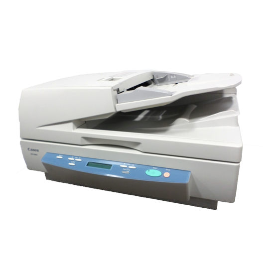
Chapter 1 Operating environment same as host machine temperature humidity *1: To enable extra-length mode, use the following service mode item: COPIER>OPTION>USER>MF-LG-SET; to enable, select '1'; to disable, select '0',which is the default. 1.2 Names of Parts 1.2.1 External View 0002-7211 F-1-1 1 Feeder cover... -
Page 17: Using The Machine
Chapter 1 1.3 Using the Machine 1.3.1 Original Placement Indicator 0002-7214 The original placement indicator goes on when an original is placed in the original tray, and it flashes to indicate the presence of a jam. Original placement indication F-1-3 1.3.2 Warning and Action to Take 0002-7215 If the original placement indicator starts to flash while an original is being moved, suspect a jam, and go through the following:... -
Page 19: Chapter 2 Functions
Chapter 2 Functions... - Page 21 Contents Contents 2.1 Basic Construction .................................2-1 2.1.1 Overview of the Electrical Circuitry............................2-1 2.1.2 Inputs to the ADF Controller PCB............................... 2-2 2.1.3 Outputs from the ADF Driver PCB ............................. 2-3 2.2 Basic Operation................................2-4 2.2.1 Routes of Drive .................................... 2-4 2.2.2 Overview of Operation Modes..............................2-4 2.2.3 Normal Rotation Pickup/Reversal Operation (single-sided original ->...
-
Page 23: Basic Construction
Chapter 2 2.1 Basic Construction 2.1.1 Overview of the Electrical Circuitry 0002-7181 The machine is not equipped with a controller PCB, and its electrical mechanisms are controlled by the reader controller PCB, which serves as a CPU (IC1). The CPU interprets signals from sensors and the host machine to generate signals used to drive DC loads (e.g., motor, solenoid) with the help of the CPU (IC9) of the ADF driver PCB. -
Page 24: Inputs To The Adf Controller Pcb
Chapter 2 2.1.2 Inputs to the ADF Controller PCB 0002-7187 Inputs to the ADF Driver PCB (1/1) ADF driver PCB J1401 J1401 Registration REG_S if paper is present, '1'. sensor J102 Release HP RE_HP_S if release motor is for lock, '1' sensor ;... -
Page 25: Outputs From The Adf Driver Pcb
Chapter 2 2.1.3 Outputs from the ADF Driver PCB 0002-7192 Outputs from the ADF Driver PCB (1/1) ADF driver PCB +24V J111 Stamp solenoid 1 STMP_SOL when '1', SL1 goes ON +24V J901 Locking solenoid 2 R_SOL when '1', SL2 goes ON. +24V J1001 Pickup clutch... -
Page 26: Basic Operation
Chapter 2 2.2 Basic Operation 2.2.1 Routes of Drive 0002-7230 The machine is a document feeder exclusively designed for stream reading mode, and it uses 4 motors and 1 clutch to control the movement of originals. T-2-1 Name Description Pickup motor (M1) picks up/feed originals Feed motor (M2) feeds originals. - Page 27 Chapter 2 1. Normal rotation picks up an original, and delivers it after it has single-sided original -> single-sided pickup/delivery been read. print single-sided original -> double-sided print extra-length original>single-sided print 2. Normal picks up an original, and reverses and double-sided original ->...
-
Page 28: Normal Rotation Pickup/Reversal Operation (Single-Sided Original -> Signal-Side Print)
Chapter 2 2.2.3 Normal Rotation Pickup/Reversal Operation (single-sided original -> signal-side print) 0002-7281 The following shows the flow of originals: Original Picking up the 1st sheet. Delivering the 1st sheet. Reading the 2nd sheet. Arching the 1st sheet. Standing by for reading the 1st sheet. -
Page 29: Normal Rotation Pickup/Delivery Operation (Double-Sided Original -> Double-Sided Print)
Chapter 2 2.2.4 Normal Rotation Pickup/Delivery Operation (double-sided original -> double-sided print) 0002-7298 The following shows the flow of originals: 1. Low speed double-sided mode a. Small-Size Original Picking up the 1st sheet. Moving the 1st sheet. Arching the 1st sheet. Turning over the 1st sheet. - Page 30 Chapter 2 Idly moving the 1st sheet. Reading the back of the Moving the 2nd sheet. 1st sheet. Picking up the 2nd sheet. Delivering the 1st sheet. Moving the 1st sheet. Reading the face of the 2nd sheet. Arching the 2nd sheet. Turning over the 1st sheet.
- Page 31 Chapter 2 b. Large size Original Picking up the 1st sheet. Moving the 1st sheet. Turning over the 1st sheet. Arching the 1st sheet. Standing by for reading Arching the 1st sheet. the 1st sheet. Reading the 1st sheet. Reading the face of the 1st sheet.
- Page 32 Chapter 2 Reading the back of Idly moving the 1st sheet. the 1st sheet. Moving the 2nd sheet. Delivering the 1st sheet. Picking up the 2nd sheet. Reading the 2nd sheet. Arching the 2nd sheet. Idly moving the 1st sheet. F-2-9 2.
- Page 33 Chapter 2 Original Picking up the 1st sheet. Moving the 1st sheet. Arching the 2nd sheet. Arching the 1st sheet. Turning over the 1st sheet. Arching the 1st sheet. Standing by for reading the 1st sheet. Reading the face of the 1st sheet. Picking up the 2nd sheet.
- Page 34 Chapter 2 Reading the back of the Idly moving the 1st sheet. 1st sheet. Moving the 2nd sheet. Moving the 2nd sheet. Arching the 3rd sheet. Moving the 1st sheet. Arching the 2nd sheet. Reading the 2nd sheet. Delivering the 1st sheet. Turning over the 1st sheet.
-
Page 35: Normal Rotation Pickup/Reversal Delivery (Double-Died Original -> Double-Sided Print)
Chapter 2 2.2.5 Normal Rotation Pickup/Reversal Delivery (double-died original -> double-sided print) 0002-7301 The following shows the flow of originals: Original Picking up the 1st sheet. Turning over the 1st sheet. Arching the 1st sheet. Arching the 1st sheet. Idly moving the 1st sheet. Idly moving 1st sheet. - Page 36 Chapter 2 Arching the 1st sheet. Standing by for reading the 1st sheet. Reading the face of the 1st sheet. Moving the 2nd sheet. Delivering the 1st sheet. Idly moving the 2nd sheet. F-2-13 2-14...
-
Page 37: Idle Feed/Reversal Pickup/Delivery (Single-Sided Original Of Mixed Configurations -> Single-Sided Print)
Chapter 2 2.2.6 Idle Feed/Reversal Pickup/Delivery (single-sided original of mixed configurations -> single-sided print) 0002-7299 The following show the flow of originals: Original Picking up the 1st sheet. Turning over the 1st sheet. Arching the 1st sheet. Arching the 1st sheet. Idly moving the 1st sheet. - Page 38 Chapter 2 Picking up the 1st sheet. Turning over the 1st sheet. Standing by for reading Arching the 1st sheet. the 1st sheet. Reading the face of the Reading the 1st sheet. 1st sheet. Reading the 1st sheet. Moving the 1st sheet. Separating the 2nd sheet.
-
Page 39: Document Detection
Chapter 2 Moving the 1st sheet. Delivering the 1st sheet. Arching the 2nd sheet. Idly moving the 2nd sheet. Turing over the 1st sheet. Arching the 2nd sheet. Moving the 1st sheet. Idly moving the 1st sheet. (while locking the platen upstream roller locked in place) Moving the 2nd sheet. -
Page 40: Checking The Presence/Absence Of An Original
Chapter 2 Item Description Sensor used (notation) Cross-feed checks the width of the original placed in the original pickup tray. original width volume direction (VR1) identification between A4R/A5R and LTRR/STMTR AB/inch sensor b. Mix of Different Configurations/Extra-Length If the originals are of different configurations or are of extra length, the following 3 detection mechanisms are used: T-2-4 Item Description... - Page 41 Chapter 2 ADF driver PCB Trailing edge of the original (small size) Trailing edge of the original Read standing by position (large size) F-2-18 When an original is placed on the original tray, the light-blocking plate operates in keeping with the detecting lever of the LGL sensor to block the light of the photo interrupter.
- Page 42 Chapter 2 ADF controller PCB Slide guide (rear) Gear Slide guide (front) F-2-20 The track of the slide guide is given a groove so that the slide may stop at specific default sizes. Some sizes, however, are extremely close to each other, possibly causing the slide to stop at the wrong point.
- Page 43 Chapter 2 F-2-21 B. Mix of Different Configurations, Extra-Length The machine measures the length of time (distance) from when the read sensor goes on to when it goes off; it then uses the result of the detection (length) and the result of detection made on the original tray to identify the size of the original.
- Page 44 Chapter 2 A4R/INCH Post-separation Width (volume; mm) sensor sensor LGL sensor Detection size (AB) 172>/= width Inch-Configuration T-2-7 Post-separation Width (volume; mm) A4R/INCH sensor sensor LGL sensor Detection size (inch) 12X18 width>289 289>/=width>269 269>/=width>247 LTRR 247>/= width>200 STMT LTRR 200>/= width>172 STMT 172>/=width STMTR...
- Page 45 Chapter 2 T-2-9 LGL sensor 247>/= width>200 LTRR The following conditions are used for making the final decision: T-2-10 length>318 318>/=width>248 LTRR 248>/=length STMT c.Mix of Different Configurations Mix of AB Configurations T-2-11 Post- A4RE/INCH separation Detection size Length (mm) Width (mm) sensor LGL sensor...
-
Page 46: Document Pickup/Separation
Chapter 2 2.4 Document Pickup/Separation 2.4.1 Basic Sequence of Operation 0002-9454 When the Start key is pressed with an original on the original tray, the machine executes the following sequence of operation to pickup up the original: a. Picking Up the Original When the pickup motor (M1) rotates in reverse and the pickup clutch (CL1) goes on, the pickup roller unit moves down to start pickup operation. -
Page 47: Pickup Unit And The Stopper
Chapter 2 registration roller No2 registration lower roller Reaing Read roller 1 Pressure roller by position Read standing by position F-2-25 e. Stream Reading The machine identifies the point of reading with reference to the pulses generated by the read motor after the read sensor goes on. When the leading edge of the original reaches the point of reading, the machine sends the image leading signal to the host machine so that the latte can start reading operation. -
Page 48: Controlling The Pickup Motor (M1)
Chapter 2 Start key ON Original placement Pickup/feed Reading Original placement sensor (P15) Pickup clutch (CL1) Arching Pickup motor (M1) Reverse rotation Normal rotation Separation rear sensor (PI7) Registration sensor (PI1) Feed motor (M2) Release motor (M4) Read sensor (PI8) Image leading edge signal :Motor reverse rotation... -
Page 49: Document Reversing
Chapter 2 2.5 Document Reversing 2.5.1 Basic Sequence of Operation 0002-9742 a. Picking Up the Original for Reading the 1st Side The platen roller rotates using the drive from the feed motor (M2) for reading the 1st side of the original. The machine keeps count of pulses from the feed motor to monitor the movement of the original;... -
Page 50: Sequence Of Operation
Chapter 2 c. Reversing/Moving the Original 2 The machine rotates the feed motor in normal direction and the delivery reversal motor in reverse to move sheets at the same time. The machine stops the delivery reversal motor when the originals have moved a specific distance. The machine then drives the lock motor for a specific number of pulses to lock the platen upstream roller in place. -
Page 51: Sequence Of Operation
Chapter 2 It then accelerates the delivery reversal motor when the trailing edge of the original leaves the platen downstream roller for delivery. The machine uses the following sequence of operation to deliver the original when the host machine finishes reading it: Delivery reversal Upper roller Read roller 2... -
Page 52: Detecting Jams
Chapter 2 +24V MODE RESET Motor Driver REF1 REF2 ADF driver PCB F-2-39 The CPU (IC9) on the ADF driver PCB receives data (command) from the host machine on printing mode (magnification, operation mode, timing); in response, it generates drive pulses to drive the feed motor (M2). The feed motor (M2) is a stepping motor, and its direction and speed of rotation are changed by changing the order of drive pulses (A, A*, B, B*). -
Page 53: Stamp Operation
Chapter 2 The machine is supplied with 2 types of power by the host machine 24 V and 13 V. The 24-V power is mainly used to drive loads (motor, clutch, solenoid), while the 13-V power is converted into 5 V by IC10 (DC-DC converter) for use by sensors and the ADF controller PCB. Unlike other models, the machine will remain supplied with power even when its feeder cover is opened. - Page 54 Chapter 2 2-32...
-
Page 55: Chapter 3 Parts Replacement Procedure
Chapter 3 Parts Replacement Procedure... - Page 57 Contents Contents 3.1 Removing from the Host Machine..........................3-1 3.1.1 Feeder......................................3-1 3.1.1.1 DADF-M1 ........................................3-1 3.2 External Covers................................3-1 3.2.1 Front Cover ....................................3-1 3.2.1.1 Removing the Front Cover....................................3-1 3.2.2 Rear Cover ....................................3-2 3.2.2.1 Removing the Rear Cover ....................................3-2 3.2.3 Lower Left Cover..................................3-2 3.2.3.1 Removing the Lower Left Cover ..................................3-2...
- Page 58 Contents 3.4.7.2 Removing the No. 2 Registration Roller ................................ 3-8 3.4.8 Delivery Reversing Roller (upper)............................... 3-9 3.4.8.1 Before Removing the Delivery Reversal (upper) ............................3-9 3.4.8.2 Removing the Delivery Reversal (upper) ............................... 3-9 3.4.9 Read Roller 1 ....................................3-9 3.4.9.1 Before Removing the Feed Motor 1 ................................3-9 3.4.9.2 Removing the Read Roller 1...................................
-
Page 59: Removing From The Host Machine
Chapter 3 3.1 Removing from the Host Machine 3.1.1 Feeder 3.1.1.1 DADF-M1 0017-6398 1) Turn off the control panel power switch [1]. 2) Turn off the main power switch [2]. 3) Disconnect the power cable (for the wall outlet) [3]. -
Page 60: Rear Cover
Chapter 3 3.2.4 Feeder Cover 3.2.4.1 Before Removing the Feeder Cover 0017-6411 1) Removing the front cover. (page 3-1)Reference[Removing the Front Cover] 3.2.4.2 Removing the Feeder Cover 0017-6408 1) Remove the E-ring [1]. F-3-8 2) Remove the feeder cover [3]. - 1 screw [1] - 1 positioning pin [2] F-3-5... -
Page 61: Removing The Pickup Motor
Chapter 3 3.3.1.2 Removing the Pickup Motor 0017-6424 1) Remove the pickup motor [3]. - 1 connector [1] - 2 bind screws [2] F-3-14 When mounting it, loosen the screws [1] to put it back to its initial position. 4) Removing the feed roller [3]. - 1 connector [1] F-3-11 - 2 screws [2]... -
Page 62: Pressurization Motor
Chapter 3 F-3-20 3) Remove the 2 screws [1]. F-3-17 2) Remove the delivery reversal motor [2]. - 2 screws [1] F-3-21 4) Remove the delivery reversal motor [3]. - 2 screws [1] - 1 connector [2] F-3-18 3.3.4 Pressurization Motor 3.3.4.1 Before Removing the Pressurization Motor 0017-6476 1) Remove the front cover. -
Page 63: Document Feeding System
Chapter 3 3.4.1.2 Removing the Pickup Roller Unit 0017-6402 1) Remove the pickup roller unit [3]. - 2 resin E-rings [1] - 2 bushings [2] F-3-24 3) Remove the drive unit [2]. - 4 screws [1] F-3-27 3.4.2 Pickup Roller / Feed Roller Be sure to free the harness from the wire saddle [3]. -
Page 64: Separation Plate/Separation Pad
Chapter 3 Moreover, be sure that the separation front guide [7] is mounted so that the spring [1] with a bend being upstream in relation to feed direction. wider side of the sheet [8] is toward the pickup roller side. 3.4.3 Separation Plate/Separation Pad 3.4.3.1 Before Removing the Separation Plate/Separation 0017-6419... -
Page 65: No.1 Registration Roller
Chapter 3 3.4.5 No.1 Registration Roller 3.4.5.1 Before Removing the No. 1 Registration Roller 0017-6441 1) Remove the front cover. (page 3-1)Reference[Removing the Front Cov- 2) Remove the rear cover. (page 3-2)Reference[Removing the Rear Cover] 3.4.5.2 Removing the No. 1 Registration Roller 0017-6446 1) Remove the harness guide [3]. -
Page 66: Removing The No. 2 Registration Roller Roll
Chapter 3 Cover] When mounting it, be sure to loosen the screws [1] and move the feed motor [2] back into its initial position. 3.4.6.2 Removing the No. 2 Registration Roller Roll 2) Remove the feed motor unit [3]. 0017-6491 1) Remove the cover [2]. -
Page 67: Delivery Reversing Roller (Upper)
Chapter 3 3.4.8 Delivery Reversing Roller (upper) 3) Remove the E-ring [1] and the bushing [2]. 3.4.8.1 Before Removing the Delivery Reversal (upper) 0017-6528 1) Remove the front cover. (page 3-1)Reference[Removing the Front Cov- 2) Remove the rear cover. (page 3-2)Reference[Removing the Rear Cover] 3.4.8.2 Removing the Delivery Reversal (upper) 0017-6531 1) Remove the delivery reversal motor unit [2]. - Page 68 Chapter 3 F-3-58 F-3-54 2) Remove the locking motor drive unit [3]. When mounting it, be sure that that timing belt [1] is properly attached to the - 3 screws [1] pulley [2]. - 1 connector [2] F-3-55 3) Remove the cooling fan [3]. - 1 screw [1] F-3-59 - 1 connector [2]...
- Page 69 Chapter 3 [1] [2] F-3-64 11) Release the pressure spring [1]. F-3-61 8) Open the open/close guide [1]; then, remove the feed guide [4]. - 2 screws [2] - 1 connector [3] F-3-65 12) Remove the 2 E-rings [1]. F-3-62 9) Remove the E-ring [1], gear [2], and bushing [3].
-
Page 70: Platen Roller
Chapter 3 F-3-70 2) Remove the platen roller [4]. - 1 belt [1] - 2 resin E-rings [2] - 2 bushings [3] F-3-67 14) Shift up the ADF, and move the reader roller 1 unit [1] as low as it moves. F-3-68 15) Remove the read roller [4]. - Page 71 Chapter 3 F-3-72 2) Remove the cooling fan [3]. - 1 screw [1] - 1 connector [2] F-3-76 5) Open the open/close guide [1]; then, remove the feed guide [4]. - 2 screws [2] - 1 connector [3] F-3-73 3) Loosen the 2 screws [1], and move the feed motor [2] down; then, tighten the 2 screws [1] you have loosened.
-
Page 72: Platen Roller Roll Downstream
Chapter 3 F-3-83 3.4.12 Platen Roller Roll Downstream F-3-80 9) Remove the 2 E-rings [1]. 3.4.12.1 Removing the Platen Roller Roll Downstream 0017-6599 1) Remove the platen downstream roll unit [2]. - 1 screw [1] F-3-81 10) Slide the bushing [1] fitted with a plate toward the rear, and detach the platen guide [2]. -
Page 73: Reversing Roller
Chapter 3 F-3-89 3) Remove the cooling fan [3]. - 1 screw [1] - 1 connector [2] F-3-86 2) Shift up the original pickup tray, and push the delivery reversal lower roll- er [1] in upward direction to detach. F-3-90 4) Loosen the 2 screws [1], and move down the feed motor [2];... -
Page 74: Reversion Roller Roll
Chapter 3 F-3-93 6) Open the open/close guide, Remove the reversing roller [4]. F-3-96 - 2 E-rings [1] - 1 gear [2] 3.4.16.2 Replacing the Open/Close Guide Sheet - 2 bushings [3] 0017-6612 1) Remove the one/close guide sheet; then, attach it while matching the cor- ners of the sheet and the guide. -
Page 75: Electrical System
Chapter 3 3.5 Electrical System 3.5.1 Fan 3.5.1.1 Before Removing the Cooling Fan 0017-6520 1) Removing the rear cover. (page 3-2)Reference[Removing the Rear Cov- 3.5.1.2 Removing the Cooling Fan 0017-6522 1) Removing the cooling fan [3]. - 1 screw [1] - 1 connector [2] F-3-102 3.5.2.3 Mounting the Document Width Volume... -
Page 76: Pressurization Solenoid
Chapter 3 10mm 10mm Right angle F-3-104 2) Set the test chart on the original pickup tray, and execute a 100% magni- fication copy. 3) Lay the test chart on top of the image outputted in step 2) to confirm the image is within the following standard value. -
Page 77: Separation Sensor
Chapter 3 F-3-109 2) Remove the ADF driver PCB [3]. - 5 connectors [1] - 2 screws [2] F-3-112 Be sure to perform sensor adjustment if you have replaced the sensor PCB. F-3-110 3.5.6 Read Sensor 3.5.5 Separation Sensor 3.5.6.1 Before Removing the Read Sensor 0017-6546 1) Remove the front cover. -
Page 78: Delivery Reversal Sensor
Chapter 3 F-3-114 If you have replaced the sensor PCB, be sure to perform sensor adjustment. 3.5.7 Delivery Reversal Sensor 3.5.7.1 Removing the Reversal Sensor 0017-6615 1) Remove the segment A, and detach the open/close guide [1] in the direc- tion of the arrow. -
Page 79: Chapter 4 Maintenance
Chapter 4 Maintenance... - Page 81 Contents Contents 4.1 User Maintenance ................................4-1 4.1.1 Cleaning ....................................... 4-1 4.1.2 Replacement....................................4-1 4.2 Maintenance and Inspection............................4-2 4.2.1 Periodically Replaced Parts ................................. 4-2 4.2.1.1 Periodically Replaced Parts.....................................4-2 4.2.2 Durables ....................................... 4-2 4.2.2.1 Durables ..........................................4-2 4.2.3 Periodical Servicing ..................................4-2 4.2.3.1 Scheduled Servicing Chart ....................................4-2 4.2.4 Cleaning .......................................
-
Page 83: User Maintenance
Chapter 4 4.1 User Maintenance 4.1.1 Cleaning 0002-9919 Advise the user to clean the following parts as necessary or every 10,000 prints without fail. T-4-1 Method Parts Intervals Remarks Wipe it with a cloth moistened Copyboard glass Reader unit parts with water (well wrung) or solution of mild detergent: Platen roller... -
Page 84: Maintenance And Inspection
Chapter 4 F-4-2 Be sure to push in the stamp until a click is felt. A gap can cause paper jams. 4.2 Maintenance and Inspection 4.2.1 Periodically Replaced Parts 4.2.1.1 Periodically Replaced Parts 0003-1674 The machine does not have parts that must be replaced on a periodical basis. 4.2.2 Durables 4.2.2.1 Durables 0003-1675... - Page 85 Chapter 4 T-4-4 Servicing*1 Parts name 80,000 originals or 6 160,000 originals or 12 months month White plate (copyboard cover) Post-separation sensor (prism) Read sensor (prism) Delivery reversal sensor (prism) No. 1 registration roller No. 1 registration roll No. 2 registration roller No.
-
Page 86: Cleaning
Chapter 4 [24] [21] [23] [25] [22] [26] F-4-4 [31] [27] [28] [29] F-4-5 4.2.4 Cleaning 4.2.4.1 Parts of the ADF 0003-1690 1. Platen Roller, Platen Upstream Roll, and Platen Downstream Roll Wipe the platen roller [1] platen upstream roll [2], and platen downstream roll [3] with a cloth moistened with water (well wrung); then, dry wipe them. 2. -
Page 87: Rollers And Guides
Chapter 4 4.2.4.2 Rollers and Guides 0003-1708 1. Original Pickup Tray Wipe the original pickup tray [1] with lint-free paper moistened with alcohol. F-4-7 2. Open/Close Guide (including sheets) and Revering Roll 1) Open the feeder cover, and detach the open/close guide. 2) Wipe the area of the open/close guide (including sheets) [1] coming into contact with paper and the reversing roll [2] found behind the open/close guide with lint-free paper moistened withalcohol. - Page 88 Chapter 4 F-4-10 2) Clean the feeder inside cover [1], feed guide [2], reversing guide [3], delivery guide [4], and registration guide [5] (including sheets) with lint-free paper mois- tened with alcohol. F-4-11 3) Remove the feeder cover and the feeder inside cover; then, clean the roll scraper [1] with lint-free paper moistened with alcohol.
- Page 89 Chapter 4 F-4-12 4. Read Roller 1 and Read Roller 2 1) Remove the 3 screws, and detach the front cover. 2) Detach the feeder cover. 3) Disconnect the connector [1], and remove the 2 screws [2]; then, detach the feed guide [3]. F-4-13 4) Clean the red roller 2 [1] and the read roller [2] with lint-free paper moistened with alcohol.
- Page 90 Chapter 4 Take care so that the lint-free paper will not touch the tip of the static eliminator. F-4-15 3) When done, mount back the inside cover. 6. Read Roll and Roll Scraper 1) Remove the lower left cover. F-4-16 2) Clean the read roll [1] and the roll scraper [2] with lint-free paper moistened with alcohol.
-
Page 91: Sensors
Chapter 4 F-4-18 4.2.4.3 Sensors 0003-2455 1. Delivery Reversal Sensor, Prism 1) Open the feed cover. 2) Remove the open/close guide. 3) Clean the prism [1] found on the back of the open/close guide using an air blower brush. F-4-19 4) Remove the delivery guide. - Page 92 Chapter 4 F-4-22 F-4-23 4) Clean the top face (plastic film) [1] of the prism. F-4-24 The surface of the prism coming in contact with paper is covered with plastic film. Be sure to clean the film. 3. Post-Separation Sensor, Prism 1) Remove the inside cover.
-
Page 93: Applying Silicone Oil To The Reading Glass (Copyboard Glass)
Chapter 4 F-4-25 3) Clean the prism [1] using a cotton swab. F-4-26 4.2.4.4 Applying Silicone Oil to the Reading Glass (copyboard glass) 0003-2473 1. Tools to Prepare i. silicone oil F-4-27 ii. cleaning tissue F-4-28 Memo: silicone oil: FY9-6013-000 cleaning tissue: FC5-4430-000 2. - Page 94 Chapter 4 F-4-29 3. Applying the Silicone Oil 1) Squeeze the silicone oil bottle [1] 2 to 3 times, thereby moistening cleaning tissue [2] with an appropriate amount of it. Avoid inhaling the vapor of the oil. F-4-30 2) Apply the silicone oil to the reading glass [1] with the cleaning tissue. F-4-31 4.
-
Page 95: Adjustment
Chapter 4 justments. 4.3 Adjustment 2) Make the following selections to highlight [SENS-IN]; FEEDER>FUNC- TION>SENS-IN. 3) Press the OK key. 4.3.1 Basic Adjustment In response, the machine will run an automatic adjustment session, and will indicate 'OK!' if it ends normally. 4.3.1.1 Overview 4) When done, end service mode. -
Page 96: Height
Chapter 4 feed direction and the host machine's scanner system: 1) Place the Test Chart in the machine, and make a copy. 2) Check the right angle of the image in relation to the leading edge of the output (i.e., angle A). F-4-33 F-4-36 4.3.1.6 Height... -
Page 97: Angle Guide (Angle Of Opening Of 70 Deg)
Chapter 4 Memo: To adjust the magnification, compare an image made in stream reading mode and an image made in copyboard mode. Unlike other ADFs, you will not be comparing a copy image and its original. 1) Using A4 or LTR paper, prepare a test chart as follows: 10mm 10mm Right angle... -
Page 98: Leading Edge Registration
Chapter 4 - if A > 1 mm, move the volume unit [6] to the front. - if B > 1 mm, move the volume unit [6] to the rear. 10mm 10mm Right angle F-4-43 2) Place the Test Chart in the original pickup tray, and make a copy at a 100% reproduction ratio. -
Page 99: White Level
Chapter 4 (unit: 0.5 mm) (range: -30- to 10; -5 to +5 mm) 6) Make a copy of the Test Chart once again, and see the image is as indicat- 4.3.1.12 White Level 0003-2377 1) Place A4 or LTRR paper on the copyboard glass, and close the machine. Make sure that the paper is not too small. -
Page 100: Motors, Clutches, Solenoids, Pcbs, And Others
Chapter 4 Name Description Notation Connecto Part No. I/O >FEEDER JAM/E code r No. Separation rear sensor detects jam FM2-1022 P005-3 0:paper 0001, 0002, 0042, 0045, 0046, 0094 present Read sensor measure original length, detects jam, controls original reading timing FM2-1022 P001-0 0:paper 0005, 0006, 0094... -
Page 101: Variable Resistors (Vr), Light-Emitting Diodes (Led), And Check Pins By Pcb
Chapter 4 PCB1 F-4-51 4.5 Variable Resistors (VR), Light-Emitting Diodes (LED), and Check Pins by PCB 4.5.1 Overview 0003-5520 Of the LEDs and check pins used in the machine, those needed for servicing the machine in the field are discussed. Do not touch the check pins not indicated in the list. - Page 103 Chapter 5 Error Code...
- Page 105 Contents Contents 5.1 Overview ..................................5-1 5.1.1 Overview...................................... 5-1 5.1.2 Error Code....................................5-1 5.2 User Error Code ................................5-2 5.2.1 Alarm Code ....................................5-2...
-
Page 107: Chapter 5 Error Code
Chapter 5 5.1 Overview 5.1.1 Overview 0004-5175 The CPU of the machine's ADF controller PCB is equipped with a function to monitor the state of the machine, flashing the Original Placement indicator when it finds a fault in the course of a check it runs as programmed. The machine communicates the presence of a fault to its host machine in the form of a code, which is any of the following 3 types;... -
Page 108: User Error Code
Chapter 5 Code Detail code Item Description E413 The level of the locking HP sensor does not change within a specific period of time. Cause: there is a fault in the locking motor or the driver PCB; there is a fault in the locking HP sensor; there has been an increase in the load of the locking cam. - Page 109 Aug 23 2007...