
Related Manuals for Brickcom VD-130A V2 Series


Summary of Contents for Brickcom VD-130A V2 Series
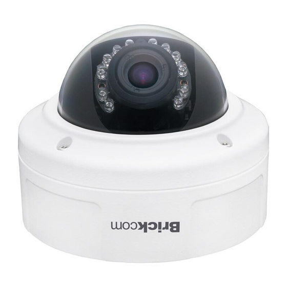
- Page 1 Megapixel Day & Night Vandal Dome Network Camera VD-100A/VD-130A V2 Series User’s Manual Quality Service Group...
- Page 2 Product name: Network Camera (VD-100A series) Release Date: 2010/10 Manual Revision: V1.1 Web site: www.brickcom.com technical@brickcom.com Email: info@brickcom.com © 2010 Brickcom Corporation. All Rights Reserved...
-
Page 3: Table Of Contents
Table of Contents Before You Use This Product ..................1 Regulatory Information ....................2 Chapter 1 - Package Contents ..................3 Chapter 2 - Vandal Dome Network Camera Overview ..........4 Chapter 3 - Device Appearance Description ............... 6 Chapter 4 - LED Behavior ..................... 7 Chapter 5 - Installation .................... - Page 4 8.4.2 E-mail Settings ..................61 8.4.3 Samba Settings ..................62 8.4.4 HTTP Settings..................63 8.4.5 Digital Output (DO) ................64 8.4.6 Video Clip ....................64 8.5 System ......................65 8.5.1 System Log .................... 65 8.5.2 Date and Time ..................67 8.5.3 Device Information .................
-
Page 5: Before You Use This Product
Before You Use This Product In many countries, there are laws prohibiting or restricting the use of surveillance devices. This Network Camera is a high-performance, web-ready camera which can be part of a flexible surveillance system. It is the user’s responsibility to ensure that the operation of this camera is legal before installing this unit for its intended use. -
Page 6: Regulatory Information
Regulatory Information Federal Communication Commission Interference Statement This equipment has been tested and found to comply with the limits for a Class B digital device, pursuant to Part 15 of the FCC Rules. These limits are designed to provide reasonable protection against harmful interference in a residential installation. This equipment generates uses and can radiate radio frequency energy and, if not installed and used in accordance with the instructions, may cause harmful interference to radio communications. -
Page 7: Chapter 1 - Package Contents
Chapter 1 - Package Contents a. Network Camera (VD-100A) b. Dry Bag, Strap Tie c. Product CD d. Location Sticker e. Warranty Card f. Screw Bag g. Terminal Block h. Allen Key i. Easy Installation Guide j. High Power PoE (Optional) -
Page 8: Chapter 2 - Vandal Dome Network Camera Overview
Chapter 2 - Vandal Dome Network Camera Overview The VANDAL DOME SERIES is a full-featured, 3-axis, fixed-dome, network camera. With a megapixel progressive sensor and built-in IR-cut filter/ IR illuminator LEDs/ Auto Light sensor, it can provide 24-hour, indoor surveillance. The VANDAL DOME SERIES features a wide-angle and vari-focal lens, which offers wide view coverage of all angles. -
Page 10: Chapter 3 - Device Appearance Description
Chapter 3 - Device Appearance Description IR LEDs LENS Tilt Screw RJ45 Connector Reset Button DIDO, Audio Terminal Block Video Adjustment Screw Power Terminal Block Conduit Plug and Conduit Hole Focus Control Bar View Angle Control Bar SD/SDHC Card Slot (*) NOTE 1. -
Page 11: Chapter 4 - Led Behavior
Chapter 4 - LED Behavior Function LED Behavior Description Power LED Continuous illumination Power on Power LED Unit Power off Link LED Continuous illumination (Orange) Link Link LED Blinking (Orange) Connecting < DI/DO Diagram >... -
Page 12: Chapter 5 - Installation
Chapter 5 - Installation 5.1 Hardware Installation a. Remove the vandal dome cover: Use the Allen Key to unscrew the four screws and remove the dome cover from the camera device. b. For SD/SDHC card (*) installation: Insert the SD/SDHC card into the SD/SDHC card slot. NOTE –... - Page 13 c. For dry bag installation: Place the dry bag on the camera device and secure it using the strap tier d. Open the conduit hole: The conduit hole will allow for air to circulate through the camera device .Use a screwdriver to unscrew either the conduit plug from the side of the camera device e.
- Page 14 f. For wall installation: i. Chose the location on the wall to place the camera. Attach the location sticker to the desired spot. ii. Drill four holes through the center of the four location holes on the sticker. iii. Hammer the four plastic anchors which are provided in the product package into the four location holes.
- Page 15 g. POE, Power, DIDO, Audio Connection: i. Insert the PoE, DIDO, and Audio cable through conduit hole A or B. ii. Connect the PoE (1), DIDO (2), and Audio (3) Cables to their respective terminals. See the next page for more details regarding the DIDO and Audio connection.
- Page 16 3) DIDO and Audio Connection Please refer to the definition of the terminal blocks below. It is also printed on the motherboard. Terminal Block Pin No. Function Pin 1 Pin 2 Pin 3 Pin 4 DIDO GND Pin 5 Audio OUT Pin 6 DGND Pin 7...
-
Page 17: Camera Connection
5.2 Camera Connection A. Basic Connection (Without PoE) a. Connect the camera device to the Ethernet hub using a RJ45 Ethernet cable. b. Connect the power adaptor to the camera device. B. Power over Ethernet (PoE) Connection a. Connect the camera to a PoE-enabled hub using a single Ethernet cable. - Page 18 C. Adjust the Lens Focus Range and Zoom Viewing a. Adjust the lens angle i. The lens can be rotated to the left or right. ii. Release the tilt screw on both side of the device to rotate the lens up or down.
- Page 19 b. Adjust the view angle and focus range i. Release the viewing angle controller bar and then slide it left or right to adjust the viewing angle. After completion, tighten the viewing angle controller. ii. Release the focus controller bar and slide it left or right to adjust the focus range.
-
Page 20: System Requirements
5.3 System Requirements Operating System: Microsoft Windows XP Home Edition SP2 Microsoft Windows XP Professional SP2 Computer: IBM PC/AT Compatible CPU: Pentium 3GHz or faster Memory: 1024 MB or more Monitor: 1024 x 768 pixels or more, 24-bit True color or better Network Interface: 10/100Mbps Network interface card must be installed Web Browser:... -
Page 21: Software Installation
A. Insert the Installation CD into the CD-ROM driver. Run Auto-Run Tool directly from the CD-ROM to start the installation. When installing the Brickcom software kit for the first time, select a desired language for the interface. The available languages are listed in the scroll box. Click <Install>... - Page 22 B. In the Install Shield Wizard dialog box, click <Next> to continue. C. Read the End-User License Agreement and check the option “I accept the terms of the license agreement”. Click <Next> to continue.
- Page 23 D. Select either “Complete” setup or “Custom” setup to install the system. a. If COMPLETE SETUP is selected: i. All program features will be installed into the default directory. Check the option “Complete” and then click <Next>. ii. Click <Change> to change the appointed folder where installation and program files will be stored.
- Page 24 iii. Select to create shortcuts. Click <Next> to continue. iv. The installation information will be displayed. Click <Next> to continue.
- Page 25 v. To launch EasyConfig or PC-NVR Standard, select the application and click <Finish>. When launching the PC-NVR program, please refer to the PC-NVR user manual. b. If CUSTOM SETUP is selected: i. This option is recommended for advanced users. It can be used to install the system to a preferred directory or to select specific program feature(s).
- Page 26 iii. Select the features to install. Click <Next> to continue. iv. Click <Change> to change the appointed folder where installation and program files will be stored. Click <Next> to continue.
- Page 27 v. Select programs to create shortcuts. Click <Next> to continue. vi. The installation information will be displayed. Click <Next> to continue.
- Page 28 E. To launch EasyConfig or PC-NVR Standard, select the application and click <Finish>. When launching the PC-NVR program, please refer to the PC-NVR user manual.
-
Page 29: Easyconfig
If Custom Setup type was used in the software installation and an EasyConfig icon was not installed on the desktop, the program will be installed under C:\Program Files\Brickcom\EasyConfig unless the program was saved to a preferred directory. A. Click <Start> to continue. The program will automatically search for the camera in the intranet. - Page 31 B. Select either “Simple Mode” or “Professional Mode” to obtain the camera’s IP settings. If “Simple Mode” is selected, EasyConfig will set up the connection automatically. If “Professional Mode” is selected, the user will need to configure the IP settings manually.
- Page 32 C. There may be many cameras in the local network. Differentiate the cameras using their UPnP name. Double click on the camera from the survey list to connect. D. For configuring the IP address settings, select either <Settings remain the same>, <Automatically obtain an IP Address (DHCP)>...
- Page 33 If <Set IP Address configuration manually> is selected, the following pages will be displayed.
- Page 34 Otherwise, this page will not be shown. *If desired, click <Skip> to skip this setting. EasyLinkTM is a unique Brickcom function which allows users to assign a unique EasyLink name to their network camera’s IP address. There is no...
- Page 35 F. When the IP address settings have been configured, the screen will either display a successful or failed connection message. If the connection failed, either try again or quit the installation. a. If “DHCP IP address settings” was selected, the failure page will be displayed as below: b.
- Page 36 c. If the connection was successful, the user will see the message: “Congratulations. The installation of the camera is complete.” When this window is displayed, click <PC-NVR> to start the PC-NVR program, <Live View> to view the live video from the connected IP camera, or <X>...
-
Page 37: Chapter 6 - Accessing The Network Camera
Chapter 6 - Accessing the Network Camera 6.1 Check Network Settings The camera can be connected either before or immediately after the software installation. The Administrator should complete the network settings on the configuration page, including entering the correct subnet mask and IP address of gateway and DNS. -
Page 38: Authentication
6.3 Authentication To access the camera’s live view, open a web browser and enter the IP address of the camera. A dialog window will pop requesting a username and password. As stated on the previous page, for the default username and password for the Administrator are assigned as “admin/admin”. -
Page 39: Installing The Plug-In
6.4 Installing the Plug-In For the initial access to the camera in Windows, the web browser may prompt the administrator for permission to install a new plug-in for on Internet Explorer. Permission request depends on the Internet security settings of the user’s PC or notebook. -
Page 40: Chapter 7 - Live View
Chapter 7 - Live View NOTE - (*) These are optional features. Please refer to the Product List for the full list of optional features available for the product. Live View is the default page that opens when accessing the camera. Live video is displayed directly in the browser window. - Page 41 b. TCP - This protocol guarantees the complete delivery of streaming data and provides better video quality. The downside of using this protocol is that the quality of its real-time effect is less than that of the UDP protocol. c. UDP - This protocol allows for more real-time audio and video streams. However, network packets may be lost due to network burst traffic and images may be broken.
- Page 42 Mute – Turn off the sound. Talk(*) – To communicate through the camera using the computer MIC. Set Default – Reset to default settings. Recording on/off - Displays the status of recording video MIC on /off - Displays the status of the MIC volume Speaker on/off - Displays the status of the Speaker MD on/off - Displays the status of Motion Detection NOTE - The <Camera Control Panel>...
-
Page 43: Chapter 8 - Configuration
Chapter 8 - Configuration Click <Configuration> on the main page to change the camera settings pages. NOTE - Only Administrators can access the Configuration page. 8.1 Camera/Video/Audio 8.1.1 Camera a. Brightness - Drag the slider bar to adjust the image brightness level from -5 to +5. - Page 44 A. Exposure Control a. Sport - Select this option when monitoring rapid moving objects. b. Normal - Select this option for normal monitoring conditions. c. Night Vision - Select this option when monitoring at night or in low light conditions. d.
- Page 45 E. Flicker-Free Eliminate the problem of flicker. Click the Radio button to select outdoor or indoor mode based on the conditions. F. True Day & Night a. Auto - The Network Camera automatically removes the filter by judging the level of ambient light. b.
-
Page 46: Video
8.1.2 Video The Network Camera offers two separate streams for different viewing options. A. Stream 1 & Stream 2 a. Video Codec - The Network Camera offers three choices of video codec standards for real-time viewing: H.264, MPEG-4 and MJPEG. b. - Page 47 NOTE - a higher bitrate will use higher network bandwidth. The video quality can be set between Level 1 to Level 6, with Level 6 producing the best image quality. e. HTTP Transport – If MJPEG is used for Video Codec, users can enable HTTP Transport protocol for video communication.
- Page 48 B. Video Overlay a. Timestamp - To display the date and time on the screen during live view, check “Enable” to enable the timestamp function and select the display position from the drop-down menu. b. Text - To make a note about the camera, check “Enable” and select the display position from the drop-down menu.
- Page 49 C. RTSP Server To utilize RTSP authentication, the user must first set a password for the camera. RTSP (Real-Time Streaming Protocol) controls the delivery of streaming media. By default the port number is set to 554. a. Authentication - Depending on the network security requirements, the camera provides two types of security settings for streaming via RTSP protocol: NONE and DIGEST.
-
Page 50: Audio
8.1.3 Audio A. Stream The administrator can set up two separate streams for the camera for different viewing devices. The administrator can enable or disable the audio function on either stream. If audio enable is selected, select the Audio codec from the drop-down menu. -
Page 51: Multicast
8.1.4 Multicast Multicast sends a video stream to the multicast group address and allows multiple clients to acquire the stream at the same time by requesting a copy from the multicast group address. Therefore, multicast can effectively save Internet bandwidth. The RTSP (Real-Time Streaming Protocol) controls the delivery of streaming media. -
Page 52: Network
8.2 Network 8.2.1 IP Settings This section explains how to configure a wired network connection for the camera. There are several ways to setup the camera over the Internet: (1) obtain an available dynamic IP address assigned by a DHCP server, (2) use a static IP, or use PPPoE (Point-to-point over Ethernet). -
Page 53: Upnp
c. PPPoE (Point-to-point over Ethernet) - Use this mode if connecting to the Internet through a DSL Line. NOTE - To utilize this feature, it requires an account provided by an Internet Service Provider. Enter the user name and password provided by the ISP. -
Page 54: Ddns (Dynamic Domain Name Service)
8.2.3 DDNS (dynamic domain name service) DDNS links a domain name to an IP address, allowing users to easily access their camera even with a changing IP address. Brickcom network cameras are compatible with two DDNS service providers (1) DynDNS, and (2) TZO. -
Page 55: Easylink Tm
8.2.4 EasyLink EasyLinkTM is a unique Brickcom function which allows users to assign a unique domain name to their network camera’s IP address. There is no need to configure the router to open up ports or remember hard-to-memorize IP addresses. -
Page 56: Http/Https
8.2.5 HTTP/HTTPS a. HTTP – (HyperText Transfer Protocol) - This protocol allows for TCP protocol quality without having to open specific ports for streaming. Users inside a firewall can utilize this protocol to allow streaming data through. b. HTTPS - (Hypertext Transfer Protocol over SSL) - This protocol allows authentication and encrypted communication over SSL (Secure Socket Layer). - Page 57 ii. Enter the User name and Password of the camera. iii. Click “Certificate Error” on the top right corner of the window to view the certificate. iv. Click “Install Certificate” and follow the steps to finish the installation.
-
Page 58: Event
8.3 Event 8.3.1 Event Settings When an event (such as unauthorized movement) occurs, the camera can be scheduled to perform certain actions. An Event Type is a set of parameters that defines these actions. This section describes how to configure the camera to perform certain actions when events occur. - Page 59 How to Set Up an Event Schedule Event Schedule describes how and when the camera performs certain actions. a. Check “Enable” and enter a descriptive name for the event schedule. b. Set Event Schedule to define when the event is activated by selecting from Always (24 hours), Schedule or Recurrence pattern.
- Page 60 ii. If Recurrence Pattern is selected, the following page will be displayed. An event schedule can be programmed to recur at different times according to the user’s needs. Select the days for the event schedule to occur. Select a start time and specify the duration. Define what will trigger an event to occur by selecting an option from the Event drop-down list.
- Page 61 i. When <Send to Email> is selected, the following page will be shown: 1) From - Enter the email address of the sender. 2) To - Enter the email address of the recipient. To enter multiple recipients, separate each using a comma. 3) My Name - Enter the sender’s name that will appear in the recipient’s inbox.
-
Page 62: Motion Detection
8.3.2 Motion Detection Motion can be detected by measuring changes in the speed or vector of an object or objects in the monitored area. This section explains how to configure the Network Camera to enable motion detection. a. Detection Setting – Use this setting to enable and define the motion detection windows. -
Page 63: Digital Input (Di)
vi. The chart below the Live View window indicates the activity level of the Motion Detection window. When motion is detected by the camera and exceeds the defined threshold, a red bar will appear. Users can use this feature as a trigger source to send photos or videos to a remote server via email or FTP. -
Page 64: Notifications
8.4 Notifications Use the tools in this section to specify what type of notification will be sent when an event occurs. The camera can send buffered images to an FTP server, Samba, Email, or HTTP. 8.4.1 FTP Settings File Transfer Protocol (FTP) is used as an application component to automatically transfer files for program internal functions. -
Page 65: E-Mail Settings
8.4.2 E-mail Settings Select “Primary Email Server” option from the Server Selection drop down menu to send media files to an email server when an event is triggered. a. SMTP Server - Enter the server host name of the email server. b. -
Page 66: Samba Settings
8.4.3 Samba Settings Select this option to send the media files via a network neighborhood when an event is triggered. a. Server Address - Enter the IP address of the Samba server. b. User Name - Enter the user name of the Samba server. Password - Enter the password of the Samba server. -
Page 67: Http Settings
8.4.4 HTTP Settings Select this option to send the media files via an HTTP notification when an event is triggered. a. URL – Specify the URL to send HTTP requests. The URL is normally written as: http://ip_address/notification.cgi?parameter ip_address – type the IP address or host name of the HTTP host. Parameter –... -
Page 68: Digital Output (Do)
8.4.5 Digital Output (DO) The DO socket allows the IP camera to send output to an external device. While executing the DO notification action, the IP camera drives voltage on the connected DO wire to the triggering voltage level for X number of seconds. -
Page 69: System
8.5 System 8.5.1 System Log a. System Log – Set up the camera to record a system log when an event is triggered. This page displays the system’s log in chronological order. The system log is stored in the camera’s buffer area and will be overwritten when the buffer area is full. - Page 70 Remote Logging - The user can configure the camera to send the system log file to a remote server as a log backup. i. Click to enable remote log and enter the IP address of the remote server. ii. Enter the port number of the remote server. Click Apply to apply settings or Cancel to cancel changes.
-
Page 71: Date And Time
8.5.2 Date and Time a. Manual – Manually enter the date and time. b. Clone from PC – The camera will sync with the time, date and time zone of the computer used to modify the camera settings. Check “Clone” to utilize this option. The read-only date and time of the PC will be displayed. -
Page 72: Device Information
8.5.3 Device Information a. System Information – Displays the complete system information of the camera. b. Network Settings – Displays the complete network settings information of the camera. Video/Audio Settings – Displays the complete video/audio settings information of the camera. -
Page 73: Storage Management(*)
8.5.4 Storage Management(*) a. Storage Management - Storage Management is used to view all the recorded files on the Micro-SD/SDHC card. i. Click Reload to refresh the list of recorded files. ii. Click Remove to safely remove the Micro-SD/SDHC memory card. iii. - Page 74 b. Advanced Settings i. Automatic Recycle(*) – Enable to automatically overwrite older files when the available space remaining on the Micro-SD/SDHC card is less than 100MB. If the Automatic Recycle function is disabled, there must be at least 50MB hard drive space available for the camera to be able to record video files.
-
Page 75: Maintenance
8.6 Maintenance 8.6.1 User Management This section explains how to enable password protection and create multiple accounts. The administrator account name is “admin”, which is permanent and cannot be deleted. a. Click Add to create an account. b. Enter the new user’s name, password and confirm password. Administrators can add up to 10 user accounts. -
Page 76: Language
i. Administrator - user has access to view and change the Configuration page. Users with administrator privilege can change other user’s access rights and user accounts. Click Delete or Update to delete or modify a user’s account. ii. Viewer - user can only access the main page for live viewing. iii. -
Page 77: Firmware Upgrade
8.6.4 Firmware Upgrade This feature allows the user to upgrade the camera firmware. It will take a few minutes to complete the process. NOTE - Do not power off the camera or camera during the upgrade. a. Upgrade - Click Browse… and specify the firmware file. Click Upgrade. The camera will begin upgrading and will reboot automatically when the upgrade is finished. -
Page 78: Reset To Default
8.6.6 Reset to Default Click Apply to restore the network camera to factory default setting. 8.6.7 Reboot This feature will reboot the camera. Click Apply to begin. A message will pop up asking “The device will reboot. Are you sure?” Click “OK” to continue. The camera will take about one minute to reboot.
Need help?
Do you have a question about the VD-130A V2 Series and is the answer not in the manual?
Questions and answers