Table of Contents
Advertisement
Quick Links
Advertisement
Table of Contents

Related Manuals for Brickcom VD-E400Af


Summary of Contents for Brickcom VD-E400Af
- Page 1 Hardware User’s Manual Megapixel Day & Night Vandal Dome Network Camera VD-E400Af...
-
Page 2: Table Of Contents
Table of Contents Before You Use This Product ..................1 Regulatory Information ....................2 Chapter 1 - Package Contents ..................3 Chapter 2 - Vandal Dome Network Camera Overview ..........4 Chapter 3 - Device Appearance Description ............... 5 Chapter 4 - LED Behavior ..................... 6 Chapter 5 - Installation .................... -
Page 3: Before You Use This Product
Before You Use This Product In many countries, there are laws prohibiting or restricting the use of surveillance devices. This Network Camera is a high-performance, web-ready camera which can be part of a flexible surveillance system. It is the user’s responsibility to ensure that the operation of this camera is legal before installing this unit for its intended use. -
Page 4: Regulatory Information
Regulatory Information Federal Communication Commission Interference Statement This equipment has been tested and found to comply with the limits for a Class B digital device, pursuant to Part 15 of the FCC Rules. These limits are designed to provide reasonable protection against harmful interference in a residential installation. This equipment generates uses and can radiate radio frequency energy and, if not installed and used in accordance with the instructions, may cause harmful interference to radio communications. -
Page 5: Chapter 1 - Package Contents
Chapter 1 - Package Contents Network Camera Location Sticker Product CD Warranty Card Easy Installation Guide Screw Bag, Wall-Mount Bracket: VDMD-B-WALL (Optional) h. High Power PoE (Optional) (Please refer to bottom message) Waterproof connector The product is intended to be supplied by a Listed Power Unit marked “L.P.S”(or “Limited Power Source”) and rated output 24V AC, 50/60 Hz, 0.7A minimum or 12V DC, 1A minimum or 48V DC, 0.25A minimum”... -
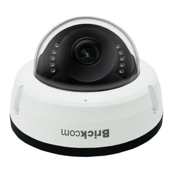
Page 6: Chapter 2 - Vandal Dome Network Camera Overview
IR-cut filter, IR LEDs, auto light sensor, and is designed to provide the 24-hour indoor and outdoor surveillance. The VD-E400Af is designed to provide the high-quality video feed for security system. The embedded high-performance image sensor and CPU allow the camera to stream the real-time, high-resolution video at 30 fps. -
Page 7: Chapter 3 - Device Appearance Description
NOTE- To avoid damaging inner cables, please avoid turning around the rotation set over 3 laps. <Rotation Limitation> Please adjust VD-E400Af Series lens+LEDs in 62.5 degree as picture bellowed for better optical performance and surveillances. -
Page 8: Chapter 4 - Led Behavior
Chapter 4 - LED Behavior Function LED Behavior Description Ethernet Link Continuous illumination (Green) Ethernet Connected Data Link Blinking (Orange) Data Transmitting Chapter 5 - Installation 5.1 Hardware Installation Use the enclosed Allen key to detach the dome cover from the camera device. Put the three waterproof rubbers which are provided in the product package into the location holes. - Page 9 <Hardware Reset > The Reset Button can be used to restore the camera to factory default settings. If the camera experiences a problem, rebooting the camera may correct the problem. If the problem remains, please restore the camera to factory default settings and set it up again.
-
Page 10: Camera Connection
5.2 Camera Connection VD-E400Af is DC12V and PoE compliant, so there are two options for connecting the camera to a power and Ethernet source. The camera can either be connected to a PoE-enabled switch or a non-PoE switch. If using a PoE-enabled switch: Use a single Ethernet cable to connect the camera to the PoE-enabled switch. -
Page 11: System Requirements
5.3 System Requirements Operating System: Microsoft Windows 8.1/8/7/Vista/XP/2000 Computer: IBM PC/AT Compatible CPU: Pentium 3GHz or faster Memory: 1024 MB or more Monitor: 1024 x 768 pixels or more, 24-bit True color or better Network Interface: 10/100Mbps Network interface card must be installed Web Browser: Microsoft Internet Explorer 6.0 SP2 or higher Adobe Reader:... -
Page 12: Software Installation
A. Insert the Installation CD into the CD-ROM driver. Run Auto-Run Tool directly from the CD-ROM to start the installation. When installing the Brickcom software kit for the first time, select a desired language for the interface. The available languages are listed in the scroll box. - Page 13 B. In the Install Shield Wizard dialog box, click <Next> to continue. C. Read the End-User License Agreement and check the option “I accept the terms of the license agreement”. Click <Next> to continue.
- Page 14 D. Click <Change> to change the appointed folder where installation and program files will be stored. Click <Next> to continue. E. Select to create shortcuts. Click <Next> to continue.
-
Page 15: Easyconfig
EasyConfig icon was installed on the desktop. Double click to launch EasyConfig. If Custom Setup type was used in the software installation but an EasyConfig icon was not installed on the desktop, by default the program is installed under “C:\Program Files\Brickcom\EasyConfig”. - Page 16 NOTE - Check <Skip the hardware installation guide> to skip checking the hardware connection. To check the hardware installation settings, do not check the option box. 1. Click <Start> to continue. The program will automatically search for the camera in the intranet.
- Page 18 2. Select either <Simple Mode> or <Professional Mode> to obtain the camera’s IP settings. If <Simple Mode> is selected, EasyConfig will set up the connection automatically. If <Professional Mode> is selected, the user will need to configure the IP settings manually. (*Please refer to point 6 for IP setting configuration.) 3.
- Page 19 4. Click <Live view> to view the live video from the connected IP camera, or <X> in the top right corner of the screen to close the installation window. 5. The internet explore will pop out a window to request username and password. For the first-time use, the default username and password are “admin/admin.”...
- Page 20 7. If <Set IP Address configuration manually> is selected, the following pages will be displayed. 8. When the IP address settings have been configured, the screen will either display a successful or failed connection message. If the connection failed, please try again or quit the installation.
Need help?
Do you have a question about the VD-E400Af and is the answer not in the manual?
Questions and answers