
Related Manuals for Hangar 9 Carden Aircraft Edition 89" Extra 300 Mid-Wing


Summary of Contents for Hangar 9 Carden Aircraft Edition 89" Extra 300 Mid-Wing
- Page 1 Instruction Manual Bedienungsanleitung Carden Edition 89˝ Extra 300 Mid-Wing Manuel d’utilisation Manuale di Istruzioni...
-
Page 2: Using The Manual
Alle Anweisungen, Garantien und anderen zugehörigen Dokumente können im eigenen Ermessen von Horizon Horizon Hobby, Inc. For up-to-date product literature, visit horizonhobby. com and click on the support tab for Hobby, Inc. jederzeit geändert werden. Die aktuelle Produktliteratur finden Sie auf horizonhobby.com unter der this product. -
Page 3: Utilisation Du Manuel
Horizon compatibili o alterare il prodotto in nessuna maniera al di fuori delle istruzioni fornite da Horizon Hobby, Inc. Hobby, Inc. Ce manuel comporte des instructions relatives à la sécurité, au fonctionnement et à l’entretien. Il Questo manuale contiene le istruzioni per un funzionamento e una manutenzione sicuri. -
Page 4: Safety Warnings And Precautions
è opportuno far riferimento appropriate Horizon Hobby office. Komponenten. Sollten Fragen zur Kompatibilität auftreten, à ce manuel ou contactez le service technique Horizon Hobby. alle istruzioni relative al prodotto o ai componenti oppure lesen Sie bitte die Produkt- oder Bedienungsanweisung oder rivolgersi al reparto Horizon Hobby di competenza. -
Page 5: Consignes De Sécurité Concernant L'utilisation
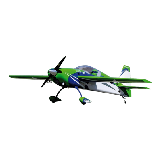
safE opErating rECoMMEndations EMpfEhlUngEn ZUM siChErEn ConsignEs dE séCUrité ConCErnant raCCoMandaZioni pEr opErarE in bEtriEb l’Utilisation siCUrEZZa • Inspect your model before every flight to ensure it is airworthy. • Überprüfen Sie zur Flugtauglichkeit ihr Modell vor jedem • Inspectez votre modèle avant chaque vol. • Controllare attentamente il modello prima di ogni volo per Flug. - Page 6 SpecificationS•Spezifikationen• Large partS Layout•BauteiLe (ohne kLeinteiLe)• SpécificationS•Specifiche eLémentS principaux•Schema dei componenti grandi 89.0 in (2.25m) 1429 sq in (92.2 dm2) 85.0 in (2.15m) 18.0–21.0 lb (8.2–9.5 kg) 2-Stroke Gas/2-Takt Benziner/ 2 temps Essence/2-Tempi Gas 50-62cc Electric Power/Elektro Antrieb/ Moteur électrique (EP)/Motore elettrico 60cc Brushless 4-channel (or greater) with 6 servos, 7 with choke, 5 for EP...
- Page 7 repLacement partS•erSatzteiLe•pièceS de rechange•ricamBi part English deutsch français italiano HAN462501 Fuselage with Hatch Kabinenhaube Fuselage avec capot Fusoliera naca pilota HAN462502 Hatch with Canopy Öffnung mit Kabinenhaube Capot avec verrière Naca pilota HAN462503 Left Wing Panel Tragfläche links Aile gauche Semiala sinistra HAN262504 Right Wing Panel...
- Page 8 aSSemBLy SymBoL guide•montage SymBoLe•guide deS SymBoLeS pour aSSemBLage•guida ai SimBoLi di aSSemBLaggio Apply threadlock Ensure free rotation Use medium CA Use a pencil Schraubensicherungslack verwenden Rotation sicherstellen Mittelflüssigen Verwenden Sie einen Bleistift Sekundenkleber verwenden Utilisez du frein filet Permettez une rotation libre Utilisez un crayon à...
- Page 9 required radio equipment•erforderLiche rc auSrüStung•equipement radio requiS•apparecchiature radio part # English deutsch français italiano SPMAR9110 AR9110 9-Channel DSMX PowerSafe Receiver AR9110 9-Kanal DSMX® PowerSafe™-Empfänger Récepteur DSMX® PowerSafe™ 9 voies AR9110 Ricevitore AR9110 DSMX® PowerSafe™ a 9 canali ® ™ SPM9645 DSMX Remote Receiver DSMX Satellitenempfänger Récepteur satellite DSMX...
- Page 10 eLectric power•eLektroantrieB•moteur eLectrique (ep)•motore eLettrico part # English deutsch français italiano HAN462523 EP Electric Motor Installation Kit Elektromotor-Montagesatz Kit d’installation de moteur électrique EP Kit di installazione per il motore elettrico 60cc Brushless Outrunner Motor 60cc Brushless Outrunner-Motor Moteur électrique Brushless à cage-tournante 60cc Motore outrunner senza spazzole 60cc CSE010007601 Phoenix Ice 2 HV160 Extreme Air BL ESC...
- Page 11 required tooLS•BenötigteS werkzeug•outiLS requiS•attrezzi neceSSari English deutsch français italiano Covering iron Folienbügeleisen Fer à entoiler Ferro da stiro per film di copertura Drill bit: 1/16-inch Bohrer: 1,5 mm Forêt : 1,5 mm Punte per trapano: 1,5 mm Flat file Flachfeile Lime plate Lima piatta Hemostats...
-
Page 12: Before Starting Assembly
bEforE starting assEMbly vor dEM ZUsaMMEnbaU avant dE CoMMEnCEr l’assEMblagE priMa di iniZiarE il Montaggio • Remove parts from bag. • Entnehmen Sie zur Überprüfung jedes Teil der Verpackung. • Retirez toutes les pièces des sachets pour les inspecter. • Togliere tutti i pezzi dalla scatola. • Inspect fuselage, wing panels, rudder and stabilizer for • Überprüfen Sie den Rumpf, Tragflächen, Seiten- und • Inspectez soigneusement le fuselage, les ailes et les... - Page 13 receiver inStaLLation•einBau deS empfängerS•inStaLLation du récepteur•inStaLLazione deL ricevitore 1 (ep onLy• nur eLektro• ep uniquement•SoLo motore eLettrico) 1 (gLow/gaS onLy• nur gLühzünder/Benzin• préChaUffagE/EssEnCE uniquement•SoLo motore gLow/a Benzina) Secure the receiver and receiver batteries in position using hook and loop tape and a hook and loop strap. The receiver is located on the top of the plate, and the batteries underneath the plate.
- Page 14 2 3 Mount two remote receivers inside the fuselage. Use hook and loop tape to secure the receivers to the left and right sides of the fuselage near the locations shown. Mount the switch to the side of the fuselage after removing the covering. Bringen Sie zwei Satellitenempfänger im Inneren des Rumpfes an.
- Page 15 rudder Servo inStaLLation•einBau deS SeitenruderServoS•inStaLLation du Servo de La gouverne de direction•inStaLLazione deL Servo deL timone 1 2 3 4 Place the rudder servo into the opening at the rear of Remove the servo and drill the locations using a pin vise and Thread a servo mounting screw into each hole to cut threads the fuselage with the output shaft facing the rear of the 5/64-inch (2mm) drill bit.
- Page 16 5 6 rudder inStaLLation•einBau deS SeitenruderS• inStaLLation de La dérive•inStaLLazione deL timone 1 2 Secure a 18-inch (457mm) extension to the servo lead using Pass the servo extension into the fuselage. Secure the servo string or dental floss. in the fuselage using the screws provided with the servo.
- Page 17 3 4 rudder Linkage inStaLLation•einBau deS SeitenrudergeStängeS• inStaLLation de La tringLerie de La dérive• installaZionE dEi tiranti dEl tiMonE 1 2 Align the hinges between the rudder and fin. Start the rudder Use a drill to hold the hinge wire. Using the drill will help hinge wire in the bottom hinge.
- Page 18 3 taiL wheeL inStaLLation•einBau deS heckradS• inStaLLation de La rouLette de queue•inStaLLazione deL ruotino di coda 1 2 3 Use the 5 -inch (140mm) adjustable turnbuckle to connect the servo to the rudder horn. Adjust the length of the linkage 4-40 x 1/2-inch 4-40 x 3/4-inch so the rudder is centered when the rudder servo is centered.
- Page 19 4 5 eLevator Servo inStaLLation•einBau deS höhenruderServoS• inStaLLation du Servo de La gouverne de profondeur• installaZionE dEl sErvo dEll’ElEvatorE 1 2 Bend the last loop on each end of the spring so it can be Attach the tail wheel spring between the tiller arm and tail attached to the tiller arm and steering arm.
- Page 20 3 4 5 6 Thread a servo mounting screw into each hole to cut threads Apply a small amount of thin CA to harden the threads made Secure the elevator servo in position using the screws Thread the control horn into position.
- Page 21 7 8 9 Secure the ball link for the rudder in the servo arm so it is Remove the servo arm from the servo. Use the radio system Use the 2-inch (51mm) adjustable turnbuckle to connect the inches (38mm) from the center of the horn.
- Page 22 aiLeron Servo inStaLLation•einBau deS querruderServoS•inStaLLation du Servo d’aiLeron•inStaLLazione deL Servo deLL’aLettone 1 2 3 4 Secure a 12-inch (305mm) extension to the servo lead using Secure the string located in the wing to the end of the Use the string to pull the extension through the wing.
- Page 23 5 6 7 8 Use a pin vise and 5/64-inch (2mm) drill bit to drill the holes Thread a servo mounting screw into each hole to cut threads Apply a small amount of thin CA to harden the threads made Secure the aileron servo in the wing using the screws for the servo mounting screws.
- Page 24 9 10 11 12 Secure the ball link for the aileron on the servo arm so it is Thread the control horn into position. Position the control Remove the servo arm from the servo. Use the radio system Use the 2-inch (51mm) adjustable turnbuckle to connect the inches (32mm) from the center of the horn.
- Page 25 Landing gear inStaLLation•montage deS fahrwerk•inStaLLation du train d’atterriSSage•inStaLLazione deL carreLLo di atterraggio 1 2 3 4 8-32 x 1 inch Secure the landing gear to the fuselage using the four screws prepared in the previous step. The gear must angle forward slightly when installed.
- Page 26 5 6 7 8 Slide the fairing away from the fuselage. Apply a thin bead Slide the fairing back into position. Use low-tack tape to hold Slide a wheel collar on the axle so it is 1/4 inch (6mm) from Place a drop of light machine oil on the axle so the wheel can of silicone adhesive to the landing gear just above the tape the fairing in position until the adhesive fully cures.
- Page 27 9 10 11 4-40 4-40 x 3/4-inch Place the wheel on the axle. Secure the wheel using a wheel Attach the axle to the landing gear using the nut provided Secure the wheel pants to the landing gear. collar.
- Page 28 gaS engine inStaLLation•Benzin motor einBau•inStaLLation du moteur a eSSence•inStaLLazione di un motore a Scoppio 1 2 3 4 1/4-20 x 1 inch When installing the DA-60 with the stock in-cowl muffler, Attach the muffler to the engine using the hardware provided it will be necessary to trim the mount blocks and motor with the engine.
- Page 29 5 6 7 8 Secure the ignition battery using hook and loop straps and Secure the ignition regulator (if required for your engine Remove the covering for the ignition switch mount. Secure Mount the fuel filler dot (HAN116) to the side of the fuselage hook and loop tape.
- Page 30 9 10 11 12 Prepare and install the servos for the throttle and choke in the servo tray. Connect the linkages to the throttle arm and choke lever. The linkages are then connetcted to the servo Assemble the throttle and choke linkages by installing the arm using an L-bend and snap keeper.
- Page 31 13 14 caniSter inStaLL•einBau deS SchaLLdämpferS• inStaLLation du réSonateur•inStaLLazione deLLa tanica 1 2 Guide the vent line through the bottom of the cowl. Führen Sie die Entlüftungsleitung durch die Unterseite der Motorhaube. Install the rubber tubing for the canister mount. This holds the canister in position during flight.
- Page 32 3 4 5 Assemble the MTW TD75K canister exhaust system. Place the clamps over the header and canister, then slide the canister and header into the coupler. Use vise-grips to open the clamps and slide them over the coupler. Slide the canister into the fuselage.
- Page 33 6 7 If using an engine such as the DA-60, drill two holes as shown to allow access to the needle valves so they can be adjusted as needed. Wenn Sie einen Motor wie den DA-60 verwenden, bohren Sie zwei Löcher (siehe Abbildung) für den Zugriff auf die Nadelventile, sodass diese nach Bedarf eingestellt werden können.
- Page 34 ep motor inStaLLation•e-motor einBau•inStaLLation du moteur ep•inStaLLazione deL motore eLettrico 1 2 3 The installation of the EP motor system is optional and will require the purchase of the HAN462523 EP Electric Motor Installation Kit for this setion of the manual. ...
- Page 35 4 5 6 7 M5 x 25 M5 x 25 Secure the motor to the motor mount. Attach the electric motor mount to the firewall using the Befestigen Sie den Motor an der Motorhalterung. hardware provided with the EP installation kit. Insert the bolts and washers through the openings on the side of the Fixez le moteur sur son support.
- Page 36 8 9 10 Secure the batteries to the battery tray. Make sure to use hook and loop tape between the batteries and battery tray to keep them from moving during extreme aerobatic maneuvers. Befestigen Sie die Akkus an der Akkuhalterung. Achten Sie darauf, dass Sie zwischen den Akkus und der Akkuhalterung Klettband anbringen, damit sich die Akkus bei extremen Flugmanövern nicht verschieben.
- Page 37 StaBiLizer inStaLLation•einBau deS höhenLeitwerkS• inStaLLation du StaBiLiSateur•inStaLLazione deLLo StaBiLizzatore 1 2 3 4-40 4-40 x 1/2-inch Slide the stabilizer tube into the stabilizer tube socket. Schieben Sie Leitwerksverbinder in die Öffnung für das Connect the elevator extension and the elevator servo. Guide Secure the stabilizer to the fuselage using the hardware Leitwerkrohr.
-
Page 38: Pilot Installation
wing inStaLLation•montage der tragfLächen•inStaLLation de L’aiLe•montaggio deLL’aLa piLot inStaLLation• einBau deS piLoten• 1 2 3 inStaLLation du piLote• installaZionE dEl pilota 1 8-32 x 1 inch Slide the wing tube into the wing tube socket. Schieben Sie den Flächenverbinder in die Öffnung an der Connect the leads from the receiver and aileron servo. - Page 39 optionaL Side force generatorS•optionaLe Seitenkraftgeneratoren• générateurS de force LatéraLe (Sfg) optionneLS•generatori di forza LateraLe opzionaLi 3 4 The installation of the Side Force Generators is laterale. optional and will require the purchase of the HAN462522 2 for this setion of the manual.
-
Page 40: Center Of Gravity
CEntEr of gravity dEr sChWErpUnkt CEntrE dE gravité centro di gravita’ (Baricentro) An important part of preparing the aircraft for flight is Ein sehr wichtiger Teil in der Flugvorbereitung ist es das Une des étapes importantes de la préparation d’un modèle Un punto importante per preparare l’aereo al volo è... -
Page 41: Control Throws
Control throWs ruderauSSchLäge 1. Turn on the transmitter and receiver of your model. Check the movement of the rudder using the transmitter. When the stick 1. Schalten Sie den Sender und Empfänger ihres Modells ein. Prüfen Sie die Seitenruderaussschläge mit dem Sender. is moved to the right, the rudder should also move right. -
Page 42: Corse Dei Comandi
débattEMEnts CorsE dEi CoMandi 1. Mettez l’émetteur et le récepteur sous tension. Contrôlez les mouvements de la dérive en utilisant votre émetteur. Quand le 1. Accendere trasmettitore e ricevitore del modello. Controllare i movimenti del timone agendo sul trasmettitore. Quando manche est vers la droite, la dérive doit s’orienter vers la droite. -
Page 43: Preflight Checklist
prEflight ChECklist vorflUgkontrollE ChECklist d’avant vol lista dEi Controlli priMa dEl volo • C harge the transmitter, receiver and motor battery for • L aden Sie den Sender- ,Empfänger- und Zündakku für • C hargez la batterie de votre émetteur, de réception • C aricare le batterie di trasmettitore, ricevitore e your airplane. Use the recommended charger supplied Ihr Flugzeug. Verwenden Sie für die RC Anlage bitte et d’allumage. -
Page 44: Daily Flight Checks
daily flight ChECks tägLicher fLug check ContrôlEs systéMatiqUEs Controlli di volo giornaliEri • C heck the battery voltage of the transmitter battery. Do • Ü berprüfen Sie die Spannung des Senderakkus. Fliegen • C ontrôlez la tension de la batterie de l’émetteur. Ne volez • C ontrollare la tensione della batteria del trasmettitore. not fly below the manufacturer’s recommended voltage. Sie nicht wenn die Spannung unterhalb der vom jamais en dessous de la tension minimale recommandée Non volare se la tensione è... -
Page 45: Limited Warranty
By the act at our facility. An Online Service Request is available at Express, and Discover cards. By submitting any item to service by anyone other than a Horizon Hobby authorized of use, setup or assembly, the user accepts all resulting http://www.horizonhobby.com/content/_service-center_ Horizon for service, you are agreeing to Horizon’s Terms and... -
Page 46: Garantie Und Service Informationen
Sollten wir nach 90 Tagen keineEinverständniserklärung zur aus. Rücksendungen durch den Käufer direkt an Horizon oder Exklusive Garantie ¬ Horizon Hobby Inc (Horizon) Muss Ihr Produkt gewartet oder repariert werden, wenden Sie Reparatur vorliegen haben, behalten wir uns vor, das Produkt eine seiner Landesvertretung bedürfen der Schriftform. -
Page 47: Garantie Et Réparations
électroniques et les moteurs. Les Garantie exclusive - Horizon Hobby, Inc. (Horizon) garantit Votre revendeur spécialisé local et le point de vente ne fonctionnement ainsi que des tentatives d’entretien ou de réparations touchant à... - Page 48 Limiti di danno manutenzione e riparazione Garanzia esclusiva - Horizon Hobby, Inc., (Horizon) Horizon non si riterrà responsabile per danni speciali, Se il prodotto deve essere ispezionato o riparato, si prega di garantisce che i prodotti acquistati (il “Prodotto”) sono diretti, indiretti o consequenziali;...
-
Page 49: Instructions For Disposal Of Weee By Users In The European Union
25337 Elmshorn, Germany service@horizonhobby.de Room 506, No. 97 Changshou Rd. +86 (021) 5180 9868 11 Rue Georges Charpak +33 (0) 1 60 18 34 90 China Horizon Hobby – China France Horizon Hobby SAS info@horizonhobby.com.cn Shanghai, China 200060 77127 Lieusaint, France infofrance@horizonhobby.com Room 506, No. -
Page 50: Ama National Model Aircraft Safety Code
aMa national ModEl airCraft safEty CodE Effective January 1, 2011 B. radio controL (rc) (h) Not operate model aircraft while under the influence of 7. Under no circumstances may a pilot or other person touch alcohol or while using any drug which could adversely affect a model aircraft in flight while it is still under power, except a. - Page 52 © 2012 Horizon Hobby, Inc. Hangar 9, DSMX, EC3, EC5, Celectra, PowerSafe, SFG Technology and the Horizon Hobby logo are trademarks or registered trademarks of Horizon Hobby, Inc. The Spektrum trademark is used with permission of Bachmann Industries, Inc. Carden Aircraft and its associated logos and body designs are either trademarks or registered trademarks of Carden Aircraft Corporation and are used under license by Horizon Hobby, Inc.
Need help?
Do you have a question about the Carden Aircraft Edition 89" Extra 300 Mid-Wing and is the answer not in the manual?
Questions and answers