Table of Contents
Advertisement
Quick Links
Specifications
Wingspan: .............. 97.5 in (2476.5mm)
Length: ................... 85 in (2159mm)
Wing Area: ............ 1730.6 sq in (111.65 sq dm)
Weight: ................... 22.5–25.5 lb (10.2 kg–11.5 kg)
Radio: ..................... 4-channel w/8 servos
Engines: ................... 3.8–4.8 cu in
WE GET PEOPLE FLYING
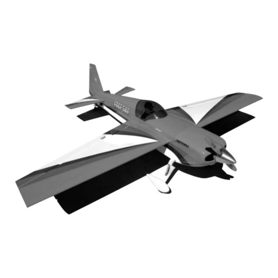
Edge 540
ASSEMBLY MANUAL
• Superior controllability and aerobatic flight characteristics
• Lightweight construction
• Designed by veteran TOC competitor Mike McConville
• 90% built 1/3-scale ARF
• Plug-in wings and stabilizers for easy transport and field assembly
TM
®
Advertisement
Table of Contents

Related Manuals for Hangar 9 Edge 540


Summary of Contents for Hangar 9 Edge 540
- Page 1 ® WE GET PEOPLE FLYING Edge 540 ASSEMBLY MANUAL Specifications Wingspan: ....97.5 in (2476.5mm) Length: ....85 in (2159mm) Wing Area: .... 1730.6 sq in (111.65 sq dm) Weight: ....22.5–25.5 lb (10.2 kg–11.5 kg) Radio: ..... 4-channel w/8 servos •...
-
Page 2: Table Of Contents
Table of Contents Using the Manual ............. . 2 Table of Contents . -
Page 3: Other Items Needed (Not Included In The Kit)
Contents of Kit Large Parts A. Fuselage w/Hatch HAN1151 B. Canopy Hatch HAN1158 C. Right Wing Panel w/Aileron HAN1152 D. Left Wing Panel w/Aileron HAN1153 E. Right Stabilizer w/Elevator HAN1154 F. Left Stabilizer w/Elevator HAN1155 G. Rudder HAN1156 H. Canopy HAN1157 I. -
Page 4: Additional Required Tools And Adhesives
Additional Required Tools and Adhesives Tools Adhesives • 4-40 tap • 6-minute epoxy • 8-32 tap • 30-minute epoxy • Adjustable wrench (small) • Thick CA (cyanoacrylate) glue • Canopy scissors • CA remover/debonder • Drill (drill press preferred) • Pacer Z-42 Threadlock •... -
Page 5: Servo Selection
Servo Selection The servos used for the control surfaces of the Edge 540 must have a minimum of 80 ounce inch of servo torque. In the prototype edges, we used JR8411 servos. On the rudder we used ONE JR8611 servo. Two servos are recommended if using other servos on the rudder. -
Page 6: Section 1 - Aileron Servo Installation
Section 1 – Aileron Servo Installation Required Parts Step 3 Tie a weight to a piece of string. A wheel collar works • Wing panel (right and left) great in this application. Lower the string into the Required Tools and Adhesives wing from the aileron servo opening. - Page 7 Section 1 – Aileron Servo Installation Step 4 Insert the servo with the 24" extension towards the tip of the wing. Use the string to pull the servo lead through the wing. Position the servo so the output shaft is towards the trailing edge of the wing. Use a 1/16”...
-
Page 8: Section 2 - Aileron Control Horn Installation
Section 2 – Aileron Control Horn Installation Required Parts Step 2 Measure exactly 3 " forward from the trailing edge • Wing panel (left and right) of the aileron and make another mark using a felt- • Aileron (left and right) tipped pen. - Page 9 Section 2 – Aileron Control Horn Installation Note: A hardwood block (hard point) is Photo for Step 6 located below the sheeting; you will be drilling through this. Make sure to drill the hole perpendicular to the top of the aileron. It is highly recommended to use a drill press to achieve this.
-
Page 10: Section 3 - Hinging And Sealing The Control Surfaces
The of 30-minute epoxy in order to achieve good Hangar 9 ® Edge 540 control surfaces are predrilled to glue joint penetration. If you notice the epoxy use Robart’s Super Hinge Points. becoming thicker, then mix a new batch! - Page 11 Section 3 – Hinging and Sealing the Control Surfaces Step 3 Step 5 Allow the epoxy to fully cure for at least 6 hours. Carefully attach the aileron to the wing, making sure When cured, work each hinge throughout its full the hinges are inserted in their respective hinge motion several times using your hands.
-
Page 12: Section 4 - Sealing The Hinge Gaps
Section 3 – Hinging and Sealing the Control Surfaces Step 7 When fully cured, move each control surface throughout its travel range several times to break away any epoxy in the hinge. Be sure to deflect the surface fully. Section 4 – Sealing the Hinge Gaps Required Parts Step 1 Cut a piece of Clear UltraCote (not included) for... - Page 13 Section 4 – Sealing the Hinge Gaps Step 2 Step 4 Using a ruler, measure 1/2" from the folded crease Mark and cut the folded covering to an overall length and mark two places with a felt-tipped pen. of 42". This piece will be inserted and ironed down into the hinge bevel on the bottom of the aileron.
-
Page 14: Section 5 - Aileron Linkage Installation
Section 5 – Aileron Linkage Installation Required Parts Note: Hangar 9 ® Titanium Pro-Links feature right-hand threads on one end and left-hand • Aluminum servo arms (4) threads on the other, allowing for easy, • Control horn ball ends (4) accurate adjustment without disconnecting •... - Page 15 Section 5 – Aileron Linkage Installation Step 4 Attach the linkage to the servo horn on the aileron. Adjust the link so the aileron is centered at the same time as the servo. Photo for Step 4 Step 5 Repeat Steps 1 through 4 for the second servo. Step 6 Repeat Steps 1 through 5 for the remaining servos in the opposite wing panel.
-
Page 16: Section 6 - Wing Installation
Section 6 – Wing Installation Required Parts Step 2 Carefully slide the remaining wing panel onto the • Wing panels • Fuselage wing tube that projects from the fuselage. The fit • Wing tube may be tight; use caution when inserting the wing •... -
Page 17: Section 7 - Elevator Construction
Section 7 – Elevator Assembly Required Parts Step 2 Tie the string around the servo lead. Pull the servo • Stabilizer (right and left) lead through the openings in the stabilizer. Install the • Fuselage servo using the hardware provided with the servo. •... - Page 18 Section 7 – Elevator Assembly Note: The technique for installing the control Step 7 horns in the elevators is similar to the aileron Mix a small amount of 30-minute epoxy and lightly control horn installation. coat the inside of the threaded holes and the 8-32 x 2"...
- Page 19 Section 7 – Elevator Assembly Step 10 Step 11 Glue the elevator hinges in place using the same Assemble and install the elevator linkage using a techniques used to hinge the ailerons. The shortened " titanium linkage. hinges will be installed into the stabilizer towards the root.
- Page 20 Section 7 – Elevator Assembly Step 14 Step 15 Drill through the hole in the stabilizer and tap for a Slide the stabilizer onto the fuselage. 4-40 bolt. Install the bolt to secure the tube. Step 16 Slide the remaining stabilizer onto the tubes and against the fuselage.
-
Page 21: Section 8 - Rudder Construction
Section 8 – Rudder Assembly Required Parts Step 4 Thread a hex nut (included with swivel clevis) onto • Rudder the threaded rod and securely tighten against the • Fuselage rudder. Screw a molded swivel link onto the threaded Required Tools and Adhesives rod so the top of the link is 7/8"... -
Page 22: Section 9 - Landing Gear Installation
Section 9 – Landing Gear Installation Required Parts Step 2 Install the landing gear using four 10-32 x 1" socket • Fuselage • Landing gear fairing head bolts, four #10 lock washers and four • 10-32 x 1" socket head bolt (4) 10-32 nylon lock nuts. -
Page 23: Section 10 - Wheel Pant Installation
Section 10 – Wheel Pant Installation Required Parts Step 3 • Wheel (2) • 3/16" wheel collar (4) Use a rotary tool or drill to make a 1/2" hole at the location made in the last step. • #4 washer (2) •... - Page 24 Section 10 – Wheel Pant Installation Step 5 Step 7 Remove the pant and use a 9/64" drill bit to drill the Secure the pant in place using a 4-40 x 1/2" socket location marked in the previous step. head screw, #4 lock washer, and #4 washer. Use threadlock on the screw to prevent it from coming Step 6 loose in flight.
-
Page 25: Section 11 - Tail Wheel Installation
Section 11 – Tail Wheel Installation Required Parts Step 4 Use two #6 x 3/4" sheet metal screws to secure the • Fuselage • Tail wheel assembly tail wheel bracket in place. A hardwood plate is Required Tools and Adhesives positioned in the rear of the fuselage, allowing these •... -
Page 26: Section 12 - Receiver, Battery And Fuel Tank Installation
Section 12 – Receiver, Battery and Fuel Tank Installation Required Parts Step 4 Assemble the tank per the instructions included with • Fuselage the tank. Be sure to use the gas-compatible stopper Required Tools and Adhesives and fuel tubing. • 1/8" light plywood •... -
Page 27: Section 13 - Mounting The Engine And Cowl
The GT80 throttle servo is positioned as shown in The Hangar 9 ® Edge 540 accepts gas engines the top of the engine box. Mount the servo using the ranging from 60 through 80cc. The prototype Edges hardware supplied with the servo. - Page 28 Section 13 – Mounting the Engine and Cowl Step 3 G62 Installation Make up the throttle linkage using a 4-40 rod and Step 1 two ball links. Carefully tap the throttle arm of the carburetor with a 4-40 tap and connect the ball link Remove the metal engine mount (if attached) from to the throttle arm.
- Page 29 Section 13 – Mounting the Engine and Cowl Step 3 Step 2 Mount the throttle servo on the bottom of the engine Use a rotary tool with a cut-off wheel and drum box 3/4" back from the front edge of the box. Use the sander to cut out a large air outlet at the aft edge of hardware supplied with the servo to attach the servo the cowling.
-
Page 30: Section 14 - Hatch Assembly
Section 14 – Hatch Assembly Required Parts Step 3 Install a 1/3-scale pilot figure to the hatch using • Hatch • Canopy Shoo Goo or similar adhesive that will remain • 4-40 x 1/2" screw (4) • #4 washer (4) flexible. -
Page 31: Section 15 - Balancing The Model
Step 5 Step 6 Lightly sand the inside edge of the canopy and Apply a bead of RCZ56 Canopy Glue (ZINJ5007) slightly inside the line drawn on the hatch using around the inside edge of the canopy. Position the medium sandpaper. canopy onto the hatch. -
Page 32: Section 17 - Control Throws
Section 16 – Radio Setup A 7-channel or greater computer radio is highly correct control direction. A servo reverser can be recommended. This allows the following features: used here. Special attention must be taken with the rudder servos so that they don’t fight each •... -
Page 33: Preflight At The Field
If not, don’t attempt to fly! Have your radio equipment checked out by the manufacturer. Setup and Flying by Mike McConville Our new Edge 540 is without a doubt our best cause control surface flutter, and on a large model, aerobatic aircraft yet. When designing this model, I this will most likely cause a crash. -
Page 34: 2004 Official Ama National Model Aircraft Safety Code
The Prototype Model Setup Computer Radio Enhancements All of the recommended settings in this manual A computer radio will allow you to do quite a bit are a result of the flight testing on the prototype of fine-tuning of the feel of the Edge, which will Edges. - Page 35 In a full-scale aerobatic plane, as well as with large models, snaps are different, particularly on the new breed of aerobatic birds like the Edge 540, which have large control surfaces.
- Page 36 Unloading Snaps That’s the whole trick. To start a snap roll, the same method as with a smaller model is used. Pull full up, full rudder and aileron in the same direction. But as soon as the sticks reach the corners, neutralize the elevator, while keeping the rudder and ailerons at full deflection.
- Page 37 Setup: Follow the 3D setup as described in the The Maneuvers manual. Be sure to use Expo. Setting the CG toward Let’s cover the seven 3D maneuvers where the Edge the aft location will help, but I have had great results 540 really excels.
- Page 38 This will help to What it is: The plane drops vertically while in a keep the Edge 540 from teetering back and forth. nose high attitude. Depending on the head wind How it’s done: At near stall airspeed up high,...
- Page 39 Setup: Full 3D throws in elevator and rudder are a The Torque Roll must. An aft CG helps a little. Also gyros provide What it is: The Edge 540 “hovers” vertically in the best aid to stabilize the aircraft. They won’t do place, rotating left around its roll axis.
- Page 40 As soon as the model is diving straight down at low throttle, add full up-elevator. If you do it right, the Edge 540 will instantly transition from a vertical dive to an Elevator. Tip: Add a little throttle just after transition to an Elevator.
- Page 41 Tip: Start a low speed and add power at the same I hope you enjoy your Edge 540 as much as I do! time that you begin to pull full up-elevator. Happy Landings! Recovery: Simply release the elevator, go to full Mike McConville throttle, and fly out upward.
- Page 42 2004 Official AMA National Model Aircraft Safety Code Effective January 1, 2003 Model Flying MUST be in accordance with this Code in order for AMA Liability Protection to apply. GENERAL 7) I will not operate models with pyrotechnics (any device that explodes, burns, or propels a projectile of any kind) 1) I will not fly my model aircraft in sanctioned events, air including, but not limited to, rockets, explosive bombs...
- Page 43 2004 Official AMA National Model Aircraft Safety Code Continued 4) I will operate my model using only radio control Organized RC Racing Event frequencies currently allowed by the Federal 10) An RC racing event, whether or not an AMA Rule Communications Commission.
- Page 44 ® WE GET PEOPLE FLYING © 2004, Horizon Hobby, Inc. 4105 Fieldstone Road Champaign, Illinois 61822 (877) 504-0233 www.horizonhobby.com 6729...
Need help?
Do you have a question about the Edge 540 and is the answer not in the manual?
Questions and answers