Table of Contents
Advertisement
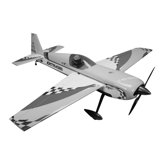
35% Extra 260
Specifications
Wingspan ......................................105 in (2667mm)
Overall Length ............ 98 in (2489mm) with spinner
Wing Area ...........................2003 sq in (129 sq dm)
Flying Weight .......................... 27–30 lb (12–14 kg)
Assembly mAnuAl
Engine Size ...................................... 100–116cc gas
Radio........................................... 4-channel or more
Servos .........................................................8 servos
(9 if using two rudder servos instead of 1)
Spinner Size .............................................. 4
Hardware Included ..............................................Yes
1
/
-inch
2
Advertisement
Table of Contents

Subscribe to Our Youtube Channel
Related Manuals for Hangar 9 Extra 260


Summary of Contents for Hangar 9 Extra 260
- Page 1 35% Extra 260 Assembly mAnuAl Specifications Wingspan ........105 in (2667mm) Engine Size ........100–116cc gas Overall Length .... 98 in (2489mm) with spinner Radio........... 4-channel or more Wing Area ......2003 sq in (129 sq dm) Servos ............8 servos Flying Weight ......27–30 lb (12–14 kg) (9 if using two rudder servos instead of 1) Spinner Size ..........
-
Page 2: Table Of Contents
Table of Contents Using the Manual ..............3 Required Tools and Adhesives . -
Page 3: Using The Manual
Before Starting Assembly Before beginning the assembly of the 35% Extra 260, remove each part from its bag for inspection. Closely inspect the fuselage, wing panels, rudder, and stabilizer for damage. If you find any damaged or missing parts, contact the place of purchase. -
Page 4: Radio And Power Systems Requirements
Radio and Power Systems Requirements • 7-channel computer radio system (minimum) w/receiver • Large Servo Arms (JRPA236) (8 pkgs) • 24-Inch Servo Lead Extension (JRPA102) (5) • JR Charge Jack Switch (JRPA004) (3) • 36-inch Servo Lead Extension (JRPA103) (3) •... -
Page 5: Warranty Period
Warranty Period Exclusive Warranty- Horizon Hobby, Inc., (Horizon) warranties that the Products purchased (the "Product") will be free from defects in materials and workmanship at the date of purchase by the Purchaser. Limited Warranty (a) This warranty is limited to the original Purchaser ("Purchaser") and is not transferable. REPAIR OR REPLACEMENT AS PROVIDED UNDER THIS WARRANTY IS THE EXCLUSIVE REMEDY OF THE PURCHASER. -
Page 6: Questions, Assistance, And Repairs
Questions, Assistance, and Repairs Your local hobby store and/or place of purchase cannot provide warranty support or repair. Once assembly, setup or use of the Product has been started, you must contact Horizon directly. This will enable Horizon to better answer your questions and service you in the event that you may need any assistance. -
Page 7: Safety, Precautions, And Warnings
Safety, Precautions, and Warnings This model is controlled by a radio signal that is subject to interference from many sources outside your control. This interference can cause momentary loss of control so it is advisable to always keep a safe distance in all directions around your model, as this margin will help to avoid collisions or injury. -
Page 8: Aileron Servo Installation
Aileron Servo Installation Required Parts Step 3 • Wing panel (left and right) Tip the wing so the root is facing down and lower the • Ball end w/hardware (4) • Control horn (4) weight through the wing. •... - Page 9 Step 5 Step 7 Use the string to pull the extension through the wing. Tape Thread the control horn onto the control horn screw so the the extension so it will not fall back into the wing. bottom of the horn is 1 inch (25mm) from the surface of the aileron.
- Page 10 Step 10 Step 12 Attach the ball end to the bottom side of the servo Assemble and install the 3-inch (76mm) linkage for the arm using the ball end hardware. The hole used will be outboard aileron servo ONLY at this time. Adjust the -inch (32mm) from the center of the servo arm.
- Page 11 Step 15 Step 18 Turn the dial on the MatchBox to position 2. Repeat for full left aileron. Step 16 Use the MatchBox to adjust the center position of the inboard servo, aligning the servo arm parallel to the hinge line.
-
Page 12: Elevator Servo Installation
Elevator Servo Installation Required Parts Step 3 • Ball end w/hardware (2) • Control horn (2) Assemble the linkage for the elevator using a ball end, • Stabilizer/elevator (left and right) control horn and a 3-inch (76mm) linkage. Thread the horn onto the screw so the bottom of the horn is 3/4-inch •... -
Page 13: Rudder And Rudder Servo Installation
Rudder and Rudder Servo Installation Required Parts Step 2 • Ball end w/hardware (2) • Control horn (2) Assemble the rudder linkage using a 4 -inch (114mm) • Rudder • Fuselage linkage, ball end and control horn. The control horn is then threaded on the control horn screw so the bottom of •... - Page 14 Step 4 Step 6 Attach the ball end to the servo horn using the hardware Drill each of the locations using a drill and 3/32-inch provided with the ball end. The attachment point will be (2.5mm) drill bit. -inch (38mm) from the center of the servo horn.
- Page 15 Step 8 Step 10 Apply a few drops of thin CA into each of the two holes to Attach the tail gear assembly to the bottom of the fuselage harden the wood. This will help in preventing the screws using two #6 x 5/8-inch socket head sheet metal screws.
-
Page 16: Landing Gear Installation
Landing Gear Installation Required Parts Step 2 • Fuselage assembly • Main landing gear Secure the axle to the main landing gear. • #8 washer (4) • 8-32 locknut (4) • Axle w/nut (2) • #4 washer (4) • 4-40 blind nut (4) •... - Page 17 Step 3 Step 5 Attach the wheel to the axle using two 5/32-inch wheel Mark the location for the two screws through the landing collars. The collars are placed on either side of the wheel. gear and onto the wheel pant using a felt-tipped pen. ...
- Page 18 Step 7 Step 8 Use pliers to install the two 4-40 blind nuts in the wheel Secure the wheel pant to the landing gear using two pant as shown. 4-40 x 1/2-inch socket head screws and two #4 washers. Note: Always use threadlock on metal-to-metal fasteners to prevent them from vibrating loose.
-
Page 19: Stabilizer Installation
Stabilizer Installation Required Parts Step 3 • Fuselage assembly • Stabilizer/elevator (2) Secure a 24-inch (610mm) servo extension to the elevator • Stabilizer tube • #4 washer (4) servo lead. Pass the extension into the fuselage, then slide the tube into the fuselage. - Page 20 Step 6 Step 8 Drill a pilot hole in the stabilizer tube using a drill and Secure the position of the tube using a 4-40 x 1/2-inch 1/16-inch (1.5mm) drill bit. socket head screw and #4 washer. The screw will thread into a blind nut that is installed inside the stabilizer.
-
Page 21: Engine Installation (Da100)
Engine Installation (DA100) Required Parts Step 3 • Fuselage assembly Use a drill and 5/16-inch (8mm) drill bit to drill the holes in the firewall for mounting the engine. Required Tools and Adhesives • Threadlock Note: For simplicity the DA will be shown with canister installation and the Evolution with Muffler installation. - Page 22 Step 6 Step 7 Use a hobby knife to trim the covering from the opening Install silicone tubes (8 total) in each of the two canister on the bottom of the fuselage. Leave enough material mounts. that you can use the covering to seal the opening with a covering iron.
- Page 23 Step 8 Step 9 Install throttle servo and attach the linkage (supplied) with Slide the canister mufflers into model and attach the a 4-40 ball link on each end. headers to the engine.
- Page 24 Step 10 Step 11 Secure the ignition module to the engine box. Make Install the switch for the ignition at the front of the the connections between the ignition box and engine fuselage as shown. at this time. ...
- Page 25 Step 14 Step 17 Cut the line between the carburetor and fuel tank to install Make a circular opening under the carb in the cowling so a Fuel Dot (HAN115). This will make fueling the tank the choke butterfly can be manually operated. much easier when the cowl is installed.
-
Page 26: Engine Installation (Evolution 116Gx)
Engine Installation (Evolution 116GX) Required Parts Step 3 • Fuselage assembly Install the tapered aluminum adapter plate to the right side of the engine with a short 1/4-20 bolt and AC nut through Required Tools and Adhesives the top mounting hole and don't tighten yet. •... - Page 27 Step 3 Step 7 Cut the top of the motor box to mount the throttle servo as Use a drill and 5/16-inch (8mm) drill bit to drill the holes photos and install it top down. in the firewall for mounting the engine. ...
- Page 28 Step 9 Step 12 Install the (supplied) throttle linkage. Use 30-minute epoxy to glue in cover plate to the fuselage for pipe tunnel. Step 10 Attach the fuel line from the fuel tank to the carburetor. Make sure the line is from the clunk and not the vent line. Cut the line between the carburetor and fuel tank to install a Fuel Dot (HAN115).
- Page 29 Step 14 Make any necessary cutouts to clear the engine components in the cowl. Remove a section from the bottom of the cowling near the mufflers for cooling outlet as shown. This opening is necessary to allow cooling air to pass through the cowling to prevent overheating of your engine.
-
Page 30: Receiver Installation
Receiver Installation Required Parts • Fuselage assembly • Hook and loop strap (4) Required Tools and Adhesives • Threadlock • Hobby knife • Receiver • Switch harness • 1/4-inch (6mm) foam) • Receiver battery • Ignition battery • 24-Inch Servo Lead Extension (JSP98040) (3) •... - Page 31 Step 4 Step 7 Use a hobby knife to remove the covering from the holes Secure any switches to the fuselage using the hardware in the sides of the fuselage for the two radio switches. provided with the switches. ...
-
Page 32: Pilot And Canopy Installation
Pilot and Canopy Installation Required Parts Step 3 • Fuselage assembly • Pilot bust Trim the instrument panel from the decal sheet. Apply the • Canopy decal in position in the cockpit. Required Tools and Adhesives Step 4 •... -
Page 33: Radio Setup
Step 6 Slip a piece of waxed paper between the hatch and fuselage. Use canopy glue to attach the canopy to the canopy hatch. Use painter's tape to keep the canopy in position until the glue fully cures. Radio Setup A 7-channel or greater computer radio is highly recommended. -
Page 34: Control Throws
Computer Radio Enhancements A computer radio will allow you to do quite a bit of fine-tuning to the feel of the Extra 260, which will make aerobatics even easier. -
Page 35: Recommended Center Of Gravity (Cg)
Rates and Expos Use Expo to soften the feel of the model. On high 3D Use low rate settings for all flying except for 3D rates, use quite a bit of expo. The goal on 3D rates is to aerobatics. For precision flying or general sport hot- get the model to feel the same around neutral as it does dogging, the low rate throws are perfect, even for snap on low rates. -
Page 36: Preflight
If the airframe goes too fast, such as While many smaller models are not critical of proper in a high throttle dive, it may fail. The Extra 260 should be battery use, and are tolerant of improper control linkage flown like a full-scale Extra 260. -
Page 37: Range Test Your Radio
Instructions for Disposal of WEEE by Users in the European Union This product must not be disposed of with other waste. will help to conserve natural resources and ensure that it Instead, it is the user’s responsibility to dispose of their is recycled in a manner that protects human health and waste equipment by handing it over to a designated the environment. -
Page 38: 2007 Official Ama National Model Aircraft Safety Code
2007 Official AMA National Model Aircraft Safety Code GENERAL 8. I will not operate model aircraft carrying pyrotechnic devices which explode burn, or propel a projectile 1. A model aircraft shall be defined as a non-human- of any kind. Exceptions include Free Flight fuses or carrying device capable of sustained flight in the devices that burn producing smoke and are securely atmosphere. - Page 39 2007 Official AMA National Model Aircraft Safety Code Radio Control 7. With the exception of events flown under official AMA rules, no powered model may be flown outdoors closer 1. All model flying shall be conducted in a manner to than 25 feet to any individual, except for the pilot and avoid over flight of unprotected people.
- Page 40 © 2007 Horizon Hobby, Inc. 4105 Fieldstone Road Champaign, Illinois 61822 (877) 504-0233 horizonhobby.com 10492.1...
Need help?
Do you have a question about the Extra 260 and is the answer not in the manual?
Questions and answers