Table of Contents
Advertisement
Quick Links
Advertisement
Table of Contents

Subscribe to Our Youtube Channel
Related Manuals for Advantech ACP-7000


Summary of Contents for Advantech ACP-7000
-
Page 1: Users Manual
ACP-7000 19" RACKMOUNT 7U HEIGHT INDUSTRIAL CHASSIS Users Manual... - Page 2 Copyright This document is copyrighted, 2000, by Advantech Co., Ltd. All rights are reserved. Advantech Co., Ltd. reserves the right to make improve- ments to the products described in this manual at any time without notice. No part of this manual may be reproduced, copied, translated or transmit- ted in any form or by any means without the prior written permission of Advantech Co., Ltd.
-
Page 3: Table Of Contents
Table of Contents Contents Chapter 1 General Information ........1 Introduction ............... 2 Specifications ..............2 Passive Backplane Options ..........3 Power Supply Options............4 System Regulation............. 5 Dimensions................ 6 Figure 1.1: Dimensions ............6 Exploded Diagram............. 7 Figure 1.2: Exploded Diagram-1........... 7 Figure 1.3: Exploded Diagram-2........... - Page 4 Figure 3.1: Alarm Board Layout ......... 26 Alarm board Specification ..........27 Switch Setting ..............31 Thermal Sensor, LED, USB and K/B ......32 Figure 3.2: Thermal Sensor..........32 Figure 3.3: Thermal Sensor Layout........32 Figure 3.4: LED layout............33 Figure 3.5: USB, PS/2 KB Layout ........
-
Page 5: Chapter 1 General Information
General Information Chapter 1 General Information... -
Page 6: Introduction
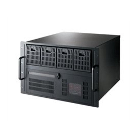
Chapter 1 Introduction 1.1 Introduction ACP-7000 is a high performance, high capacity-computing platform which meets a variety of needs including filing, printing, applications, e- mails and Web server. This powerful departmental server includes a full Disk Array of high availability features for minimizing the system down- time especially in mission-critical CT application and factory manage- ment. -
Page 7: Passive Backplane Options
Operation Temperature:0°C ~ 40°C (32°F ~ 104°F) Storage Temperature: -40° to +60°C (-40° to +140°F) Relative Humidity: 10 ~ 95%@40°C, non-condensing Vibration (operating): 5Hz ~ 500Hz, 1G rams, 2G(non-operating) Shock (non-operating): 30 G with 11m Sec duration, 1/2 sine wave Altitude: 0 to 3048m (0 to 10,000 ft) Slide Rail:General Device C-300 series supported Safety: UL, cUL, CE... -
Page 8: Power Supply Options
+5 V @ UL, cUL- 259,000 810H ATX PFC 240Vac(F 75A+3.3V 9A+3.3 V hours ull-range) @60A+12 @ 3A+12 @25°C V@51A- V @ 4.5 (Full load) 12V@1.5 A-12 V @ 0.15A-5 V 5V@1.5A +5Vsb@1 0.15A+5V sb @ 0.15A ACP-7000 User’s Manual... -
Page 9: System Regulation
1.5 System Regulation Model name Specification Safety ACP-7000BP-00R Without backplane, without Power Supply(20-B/P ver- sion, for redundant power) ACP-7000BP-00N Without backplane, without Power Supply(20-B/P ver- sion, for 2+1 or 3+1 power) ACP-7000BP-46R With 460W ATX PFC Redun- UL.cULCE dant Power Supply without backplane (20-Slot backplane version) ACP-7000BP-57N... -
Page 10: Dimensions
1.6 Dimensions Unit : mm [inch] Figure 1.1: Dimensions ACP-7000 User’s Manual... -
Page 11: Exploded Diagram
1.7 Exploded Diagram Figure 1.2: Exploded Diagram-1 Figure 1.3: Exploded Diagram-2 Chapter 1 General Information... -
Page 12: Figure 1.4: Exploded Diagram 3
Figure 1.4: Exploded Diagram 3 ACP-7000 User’s Manual... -
Page 13: Chapter 2 System Setup
System Setup Chapter 2 System Setup... -
Page 14: System Installation
2.1.2 Removing the top cover and backplane holder First, remove the chassis cover. The top cover is fixed to the chassis by two thumbscrews. Release two thumbscrews on the rear upper location of the chassis. Lift the cover. Figure 2.1: Top Cover ACP-7000 User’s Manual... -
Page 15: Figure 2.2: Front Panel Switches
2.1.3 Chassis Front and Rear Sections The front panel switches behind the door are used for system power, sys- tem reset 1, system reset 2 (option), alarm reset , power switch, USB and PS/2 keyboard. A multi-function key lock locks the door cover; user could lock the door cover by key or without key. -
Page 16: Figure 2.4: Rear View
USB connector: If you want to connect any USB interface device to the system, you could use this connector. PS/2 connector: If you want to connect the PS/2 keyboard, you could use this connector. ACP-7000 User’s Manual... -
Page 17: Figure 2.5: Backplane Holder
ATX M/B I/O cover and sheet metal kit for single or 1+1 redun- dant power. 2.1.4 Drive Bay & SCSI Storage Installation The Standard Drive Bay of the ACP-7000 can hold a slim type CD-ROM, 5.25"(x2) and 3.5" (x1) devices Installation disk drives Remove the top cover Release two thumbscrews to draw out the backplane holder until you have enough space to take out driver bay. -
Page 18: Figure 2.6: Driver Bay
Returning and push the mobile drawer within HDD toward to the SCSI storage until the handle of mobile drawer is moving up. See Figure 2.10 Push the handle of mobile drawer until the end, and then press the latch to the down location. ACP-7000 User’s Manual... -
Page 19: Figure 2.7: 3.5" Mobile Drawer Latch
The Latch has to be on upper location Figure 2.7: 3.5" Mobile Drawer Latch Figure 2.8: 3.5" Mobile Drawer Handle Chapter 2 System Setup... -
Page 20: Figure 2.9: Scsi Sca-2 Hdd
Find the location of PCI or ISA slot, take out the I/O bracket first, and install add-on card. After all the CPU card and add-on cards installation, fix them tightly with backplane holder by screw and fix them well by cardholder. ACP-7000 User’s Manual... -
Page 21: Figure 2.11:5Vsb/Ps_On Cable
5Vsb/PS_ON cable connect to SBC Figure 2.11: 5Vsb/PS_ON cable 2.1.6 ACP-7000BP-00R, ACP-7000BP-00N ACP-7000BP-00R has a momentary switch on the front panel. It is 20-slot backplane version but without backplane and power supply inside; it is with the mechanical design for 1+1 redundant power supply. ACP-7000BP-46R, see Figure 2.12, is without backplane;... -
Page 22: Figure 2.13:Acp-7000Bp-57N/81N
ACP-7000MB-00X, has a momentary switch on the front panel and is for ATX M/B or two ways Server Board. It is without motherboard and power supply inside; and the mechanical design is for ATX single PS/2 type power supply. ACP-7000MB-00R is complete same as ACP- ACP-7000 User’s Manual... -
Page 23: Figure 2.15:Acp-7000Mb-00X
7000MB-00X; but the mechanical design is for 1+1 redundant power supply. For ACP-7000MB-40Z, sees Figure 2.15, it is with 400W ATX PFC PS/2 single power supply. For the ACP-7000MB-46R, see Figure 2.16, you will understand it is with 460W 1+1 redundant power supply inside. -
Page 24: Led Indicators
An audible alarm is activated. To stop the alarm buzzer, press the Alarm Reset button. Inspect the rear section and fan fil- ter immediately. Make sure airflow inside the chassis is smooth and not blocked by dust or other particles. ACP-7000 User’s Manual... -
Page 25: Scsi Storage
2.2.2 Power Status LED The Power Status LED indicates the status of the backplane voltage sig- nals. Description Light No light +3.3V +3.3V signal Normal No output + 5V signal Normal No output +12V +12V signal Normal No output - 5V signal Normal No output -12V... -
Page 26: Figure 2.17:Scsi Storage Cabling
There are three locations of front door with the filter. If the filter is blocked with dust or other particles, you can refer to Figure 2.20 for filter replacement. For each hot-swappable cooling fan is with filter inside. See Figure 2.21. ACP-7000 User’s Manual... -
Page 27: Figure 2.18:System H/S Cooling Fans
Figure 2.18: System H/S Cooling Fans Figure 2.19: SCSI Storage Cooling Fans Figure 2.20: Front Door Filter Chapter 2 System Setup... -
Page 28: Figure 2.21:H/S Cooling Fan Filter
Figure 2.21: H/S Cooling Fan Filter ACP-7000 User’s Manual... -
Page 29: Chapter 3 Alarm Board
Alarm Board Chapter 3 Alarm Board... -
Page 30: Alarm Board Layout
Temperature inside the chassis rises over 50°C(default setting) A problem occurs in one of the backplane voltage levels The detailed layout and specification of the alarm board are as follows: 3.1 Alarm board layout Figure 3.1: Alarm Board Layout ACP-7000 User’s Manual... -
Page 31: Alarm Board Specification
3.2 Alarm board Specification Input Power: +5V, +12V Input Signals: • 7 FAN connectors (Pin 1: GND, Pin 2: +12V, Pin 3: FAN Signal) • One thermal board connector (it can connect up to 8 thermal boards in a roll) •... - Page 32 Pin 9 : ATX ON Pin 10 : DO 4 Pin 11 : GND Pin 12 : DO 3 Pin 13 : Watchdog IN Pin 14 : DO 2 Pin 15 : Watchdog OUT Pin 16 : DO 1 ACP-7000 User’s Manual...
- Page 33 Pin 17 : SPLED Pin 18 : NC Pin 19 : LILED Pin 20 : NC Pin 21 : GND Pin 22 : NC Pin 23 : TX+ Pin 24 : NC Pin 25 : TX- Pin 26 : NC Pin 27 : RX+ Pin 28 : NC Pin 29 : RX-...
- Page 34 Pin 2 : ATX Momentary switch(-) Pin 3 : GND Pin 4 : System Reset Signal Pin 5 : Watch Dog IN Pin 6 : Watch Dog OUT J1 : External Speaker Pin 1 : Buzzer Pin 2 : +5V ACP-7000 User’s Manual...
-
Page 35: Switch Setting
3.3 Switch Setting Table 1: Fan Number Setting FAN NUM- SW1- 1 SW1 - 2 SW1 - 3 SW1 - 4 Table 2: Thermal Board Temperature Setting TEMP INDEX SW 1 - 1 SW 1 - 2 SW 1 - 3 SW 1- 4 TEMP 1 TEMP 2... -
Page 36: Thermal Sensor, Led, Usb And K/B
Pin Definition CN1~2: I2C Sensor board (LM75) Connector Pin 1: +5V Pin 2: Sensor board I2C bus clock Pin 3: Sensor board I2C bus data Pin 4: GND Figure 3.2: Thermal Sensor Figure 3.3: Thermal Sensor Layout ACP-7000 User’s Manual... -
Page 37: Figure 3.4: Led Layout
There is a system LED indicator on the front door. See Figure 3.4 for the connection. Pin Definition CN1: LED Board Connector Pin 1: GND Pin 2: +5V Signal Pin 3: +12V Signal Pin 4: -5V Signal Pin 5: -12V Signal Pin 6: HDD 1 Pin 7: Power Good Signal Pin 8: Power Fail Signal... -
Page 38: Figure 3.5: Usb, Ps/2 Kb Layout
Pin 2: USBD0- Pin 3: USBD0+ Pin 4: USBG0 Pin 5: GND Pin 6: USBV1 Pin 7: USBD1- Pin 8: USBD1+ Pin 9: USBG1 CN3: PS/2 Keyboard Connector CN4: USB Connector Figure 3.5: USB, PS/2 KB Layout ACP-7000 User’s Manual... -
Page 39: Chapter 4 Scsi Storage
Chapter 4 Ducks that Need Love! SCSI Storage Chapter 4 SCSI Storage... -
Page 40: 6-Slot Sca Backplane Layout
Chapter 4 SCSI Storage 4.1 6-slot SCA Backplane Layout Pin Definition J1: On Board Terminator Enable/Disable Enable: Pin 2-3 short Disable: Pin 1-2 short J2: SAF-TE Chip ID Select ID 6: Pin 2-3 short ID 8: Pin 1-2 short J3: SAF-TE Enable/Disable Enable: Pin 2-3 short Disable: Pin 1-2 short J4: Reserved for system JP1: HDD Spin up Option... -
Page 41: Figure 4.1: Sca Backplane Layout
LCD, etc), hot-swapping of hard drivers, and monitoring of enclo- sure components, such as disks, power supplies, temperature, fans, etc.). For ACP-7000, the GEM 318 checks the disks status only, for others as fans, temperature, power supply and voltage are monitored by alarm board. -
Page 42: Raid
ACP-7000 but be careful the length limitation. The max length of your RAID controller has to be under "240mm" to install into ACP-7000. See the figure 4.2 to watch out the limitation.
Need help?
Do you have a question about the ACP-7000 and is the answer not in the manual?
Questions and answers