Table of Contents
Advertisement
Quick Links
Advertisement
Table of Contents

Subscribe to Our Youtube Channel
Related Manuals for Advantech ACP-1320BP


Summary of Contents for Advantech ACP-1320BP
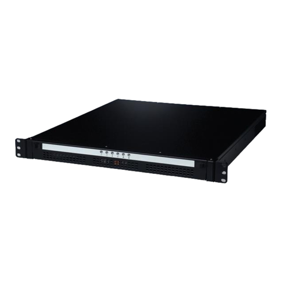
- Page 1 User Manual ACP-1320BP 1U-high Rackmount IPC Chassis with Dual SATA Storage Trays...
- Page 2 No part of this manual may be reproduced, copied, translated or transmitted in any form or by any means without the prior written permission of Advantech Co., Ltd. Information provided in this manual is intended to be accurate and reliable. How- ever, Advantech Co., Ltd.
- Page 3 Because of Advantech’s high quality-control standards and rigorous testing, most of our customers never need to use our repair service. If an Advantech product is defec- tive, it will be repaired or replaced at no charge during the warranty period. For out- of-warranty repairs, you will be billed according to the cost of replacement materials, service time and freight.
- Page 4 Also notify the carrier. Retain the shipping carton and packing material for inspection by the carrier. After inspection, we will make arrange- ments to repair or replace the unit. ACP-1320BP User Manual...
-
Page 5: Declaration Of Conformity
Opera- tion of this equipment in a residential area is likely to cause harmful interference in which case the user will be required to correct the interference at his own expense. ACP-1320BP User Manual... - Page 6 Technical Support and Assistance Visit the Advantech web site at www.advantech.com/support where you can find the latest information about the product. Contact your distributor, sales representative, or Advantech's customer service center for technical support if you need additional assistance. Please have the following information ready before you call: –...
- Page 7 Discard used batteries according to the manufacturer's instructions. Document Feedback To assist us in making improvements to this manual, we would welcome comments and constructive criticism. Please send all such - in writing to: support@advan- tech.com ACP-1320BP User Manual...
-
Page 8: Safety Instructions
The sound pressure level at the operator's position according to IEC 704-1:1982 is no more than 70 dB (A). DISCLAIMER: This set of instructions is given according to IEC 704-1. Advantech disclaims all responsibility for the accuracy of any statements contained herein. - Page 9 PC is on. Take anti-static precautions before making any configuration changes. Other- wise, electrostatic discharges can occur when connecting a jumper or installing a card or other device; these discharges can severely damage sensitive elec- tronic components. ACP-1320BP User Manual...
- Page 10 ACP-1320BP User Manual...
-
Page 11: Table Of Contents
Power Supply Options................3 Table 1.1: Power supply options for BACKPLANE version ..3 Environmental Specifications ..............3 Table 1.2: Environment specifications........3 Dimension of ACP-1320BP............... 4 Figure 1.1 Dimension of ACP-1320BP ........4 Chapter System Setup ........5 Introduction ....................6 Removing the cover .................. - Page 12 Exploded Diagram .................. 24 Figure A.1 Exploded Diagram............ 24 Table A.1: Parts List ..............24 Appendix B Backplane Options ......25 Backplane Options.................. 26 Table B.1: PICMG1.3 Backplane Options ......... 26 Table B.2: PICMG1.0 Backplane Options ......... 26 ACP-1320BP User Manual...
-
Page 13: Chapter 1 General Information
Chapter General Information... -
Page 14: Introduction
And more ACP-1320BP comes with a 300W ATX 1U-high power supply; a 250W power supply is available for customized projects. Streamlined with an efficient cooling design, the in-chassis airflow keeps the system from over-heating. All these outstanding features make ACP-1320BP the best choice for price, performance, and total cost of owner- ship. -
Page 15: Power Supply Options
-20 to 60° C (-4 to 140° F) Temperature 10 to 85% @ 40° C 10 to 95% @ 40° C Humidity non-condensing non-condensing Vibration 0.5G rms (5 ~ 500Hz) 0 to 3,048 m (0 ~ 10,000 ft) Altitude CE compliant Safety ACP-1320BP User Manual... -
Page 16: Dimension Of Acp-1320Bp
Dimensions of ACP-1320BP Figure 1.1 Dimensions of ACP-1320BP ACP-1320BP User Manual... -
Page 17: Chapter 2 System Setup
Chapter System Setup... -
Page 18: Introduction
ACP-1320BP chassis. Please also refer to the Appendix A, Exploded Diagram, for the parts naming in this manual. Removing the cover To remove the cover of the ACP-1320BP, please refer to Figure 2-1. Remove screws; slide cover back; lift cover up. Figure 2.1 Removing the cover... -
Page 19: Installing The Backplane And The Cpu Card
Installing the backplane and the CPU card ACP-1320BP accepts 3-slot backplane. To install the backplane, refer to figures and proceed as follows: Note! To ensure the best air flow inside the chassis, choosing a CPU cooler which is lower than 22 mm is highly recommended. -
Page 20: Installing Add-On Cards
2.5.1 Installing a SATA HDD in the SATA HDD tray ACP-1320BP accepts both SATA and SATA II HDD. It is not necessary to remove ACP-1320BP’s cover when installing a SATA HDD in any of the SATA HDD trays. Figure 2.3 Removing the front bezel of the drive bay... -
Page 21: Installing A 3.5" Hdd/Fdd In The 3.5" Drive Bay And A Slim-Type Cd-Rom/-Rw
Open the front bezel of the drive bay. If you want to install a SATA HDD into SATA tray, it is necessary to remove the front bezel first. The front bezel is attached to the ACP-1320BP with bezel latch, but NOT fixed with screws. - Page 22 Figure 2.5 Small converter for slim-type optical disk drive Figure 2.6 Installing an HDD/FDD and slim-type optical disk in the 3.5” drive ACP-1320BP User Manual...
-
Page 23: Chapter 3 Operation
Chapter Operation... -
Page 24: The Front Panel
Whenever a fault occurs in the system (e.g., fan failure or the chassis is overheated), the audible alarm will be activated. Pressing this button will stop the alarm from beep- ing. Dual USB ports: For connecting a wide range of USB devices for data transfer, backup or input. ACP-1320BP User Manual... -
Page 25: Led Indicators
If the LAN1/LAN2 LED stays GREEN, it means the network connection works nor- mally. When data is transmitting through the network, the LAN LED blinks. When the LAN1/LAN2 LED fails to light up, inspect the LAN cable and the connections. ACP-1320BP User Manual... -
Page 26: Table 3.2: Table 3.2: Sata Hdd Led Indicators Function For Acp 1320
LED is GREEN. If it fails to light up, check if you connected the SATA HDD well. Or please ask the technician to inspect the related cables in the chassis. When the SATA HDD is transmitting some data, the status LED is blinks BLUE. ACP-1320BP User Manual... -
Page 27: Replacing The Cooling Fans
Replacing the Cooling Fans There are two fans close to the rear window of the ACP-1320BP chassis. Un-plug the fan power connector. Remove the two screws, which mount the fan bracket on the chassis, and take it out. Remove the screws, which mount the failed fan to the fan bracket, and take out the fan. -
Page 28: Replacing The Power Supply
Replacing the power supply ACP-1320BP supports a single 1U-high power supply. To change the power supply, refer to Figure 3.4 and proceed as follows: Un-plug the AC inlet from the power supply of ACP-1320BP. Remove the top cover of ACP-1320BP. -
Page 29: Chapter 4 Alarm Board
Chapter Alarm Board... -
Page 30: Introduction
One ‘voltage signal’ connector (connect from the backplane, and support six ± ± voltages: 12 V, 5 V, +3.3V, +5 Vsb) One ‘hard disk LED’ connector (connect from the CPU card or the motherboard) Output Signals: One ‘LED board’ connector One ‘buzzer’ output ACP-1320BP User Manual... -
Page 31: Connectors, Jumper And Pin Definition
Table 4.9: J1, External buzzer Pin 1 Buzzer Pin 2 +5 V Table 4.10: SW1, Fan number select switch Pin 1 Pin 5 Pin 2 FAN_SEL1 Pin 6 FAN_SEL3 Pin 3 Pin 7 Pin 4 FAN_SEL2 Pin 8 RESET ACP-1320BP User Manual... -
Page 32: Switch Settings
The ACP-1320 is configured with a thermal sensor located at the rear plate of the chassis. (see Figure 4.2) Please refer to Figure 4.3 for a diagram of the thermal sen- sor module layout. Figure 4.2 Thermal sensor location ACP-1320BP User Manual... -
Page 33: Figure 4.3 Thermal Sensor Module
+5 V Pin 3 T_SDAT Pin 2 T_SCLK Pin 4 Table 4.13: SW1, Thermal sensor I.D. number setting Sensor I.D. No. SW 1 -1 SW 1 - 2 SW 1 - 3 SW 1 - 4 1 (default) ACP-1320BP User Manual... - Page 34 ACP-1320BP User Manual...
- Page 35 Appendix Exploded Diagram...
-
Page 36: A.1 Exploded Diagram
Power Front door System fan x 1(40*28mm) LED housing Thermal board USB cable Common alarm Switch holder PCB guide rail System Reset Switch Card guide Alarm Reset Switch Fan holder 2 Rack mount bracket Dual system fan(40*28mm) ACP-1320BP User Manual... - Page 37 Appendix Backplane Options...
-
Page 38: B.1 Backplane Options
Backplane Options ACP-1320BP supports a variety of PICMG 1.0/1.3 backplanes. Please contact a local sales representative for detailed information. Table B.1: PICMG1.3 Backplane Options Slots Per Segment Model Name Segment SHB* PCIe x 16 PCIe x 4 PCE-5B03V-01A1E Single PCE-5B03V-00A1E... - Page 39 ACP-1320BP User Manual...
- Page 40 No part of this publication may be reproduced in any form or by any means, electronic, photocopying, recording or otherwise, without prior written permis- sion of the publisher. All brand and product names are trademarks or registered trademarks of their respective companies. © Advantech Co., Ltd. 2008...
Need help?
Do you have a question about the ACP-1320BP and is the answer not in the manual?
Questions and answers