
Related Manuals for Advantech ACP-4320


Summary of Contents for Advantech ACP-4320
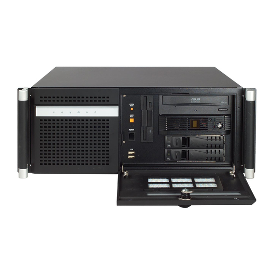
- Page 1 User Manual ACP-4320 4U Industrial Chassis with Dual Front-accessible SAS/SATA HDD Trays...
- Page 2 No part of this manual may be reproduced, copied, translated or transmitted in any form or by any means without the prior written permission of Advantech Co., Ltd. Information provided in this manual is intended to be accurate and reliable. How- ever, Advantech Co., Ltd.
-
Page 3: Safety Instructions
PRIATE SAFETY STANDARDS INCLUDING IEC 60825. CLASS I LASER PRODUCT KLASS I LASER PRODUKT This device complies with Part 15 of the FCC rules. Operation is subject to the following two conditions: (1). this device may not cause harmful interference, and ACP-4320 User Manual... - Page 4 Advantech has come to be known. Your satisfaction is our primary concern. Here is a guide to Advantech’s cus- tomer services.
-
Page 5: Product Warranty
If an Advantech product is defective, it will be repaired or replaced at no charge dur- ing the warranty period. For out-of-warranty repairs, you will be billed according to the cost of replacement materials, service time and freight. - Page 6 ACP-4320 User Manual...
-
Page 7: Table Of Contents
Switch and buttons..............16 Figure 3.1 The switch & buttons on the front panel ....16 3.1.2 LED indicators for System Status ..........16 Figure 3.2 The LEDs on the front panel........16 Table 3.1: LED definition summary ........... 16 ACP-4320 User Manual... - Page 8 Options. 31 Backplane Options.................. 32 Table B.1: PICMG 1.3 Backplane Options ........ 32 Table B.2: PICMG 1.0 Backplane options ......... 32 Motherboard Options ................33 Table B.3: ATX Motherboard Options........33 Table B.4: MicroATX Motherboard Options....... 33 ACP-4320 User Manual viii...
-
Page 9: Chapter 1 General Information
Chapter General Information This chapter provides general information about the ACP-4320. Sections include: ! Introduction ! Specifications ! Power supply options ! Environment specification ! Dimension diagram... -
Page 10: Introduction
Versatile industrial features The ACP-4320 supports either an ATX or a MicroATX motherboard, plus an up-to-15- slot PICMG 1.0 backplane or 12-slot PICMG1.3 express backplane, bringing users flexibility for their system configuration planning. -
Page 11: Power Supply Options
@ 1.2 A, +5 VSB @ 2 A Minimum load +5 V @ 3 A, +3.3 V @ 1 A, +12 V @ 2 A, +5 VSB @ 0.1 A MTBF 100,000 hours @ 25°C Safety UL/TUV/CB/CC ACP-4320 User Manual... -
Page 12: Environment Specifications
10~95% @ 40C, non-condensing non-condensing Vibration (5 ~ 500 MHz) 1G rms Shock 10G (with 11 ms duration, half sine wave) Safety CE compliant Dimension Diagram MB Version BP Version Unit: mm (inch) Figure 1.1 Diagram diagram ACP-4320 User Manual... -
Page 13: Chapter 2 System Setup
Chapter System Setup This chapter introduces the instal- lation process. Sections include: ! Installing the backplane or motherboard ! Installing CPU card or add-on card ! Installing disk drives ! Attaching the ears and handles... -
Page 14: Removing The Top Cover
The following procedures are provided to assist you in installing a motherboard (or backplane), disk drives, and plug-in cards into the ACP-4320. Please also refer to the Appendix A, Exploded Diagram, for the detail parts of the chassis. Removing the Top Cover To remove the top cover, please refer to Figure 2.1. -
Page 15: Table 2.1: Yellow Label Indicating Copper Stub Locations
Connect the wires for the POWER LED, HDD LED and LAN LED from the moth- erboard to the small LED board, which is attached to the front panel of the chas- sis. Note! AIMB-74X series motherboards don't support front LAN LED function. ACP-4320 User Manual... -
Page 16: Figure 2.2 Installing A Backplane
Insert the CPU card (with CPU, CPU cooler, RAM, and necessary cables installed) or add-on card vertically into the proper slot. For full-length CPU card, please make sure that the card bracket has been inserted properly and the ACP-4320 User Manual... -
Page 17: Figure 2.4 Installing A Cpu Card
Figure 2.4 Installing a CPU card Note! Most of Advantech's full-sized CPU cards support the front USB func- tion. However, only the PCA-6184-B, PCA-6186-B, PCA-6188, PCA- 6190 and the later full-sized CPU cards support the front LAN LED func- tion. -
Page 18: Hold-Down Clamp
(see Figure 2.5) Secure the hold-down clamp into its original position. Figure 2.5 Installing rubber cushions and hold-down clamp ACP-4320 User Manual... -
Page 19: Installing Disk Drives
Installing Disk Drives The ACP-4320 comes with two front-accessible SAS/SATA HDD trays; it also sup- ports two 5.25" disk drives and one 3.5"flppy disk drive or an internal SATA/ATA hard disk drive. Note! For the first time installing all disk drives together into the ACP-4320 chassis, we suggest users install the two 5.25"... -
Page 20: Installing A 3.5" Floppy Disk Drive
2.5.4 Installing a SAS/SATA HDD in the front-accessible HDD tray ACP-4320 accepts both SAS and SATA HDDs. It is not necessary to remove top cover when installing a SAS or SATA HDD in any of the front-accessible HDD trays. Left-shift the key latch of one HDD tray to unlock the tray. Hold the handle of the tray and draw it out from the chassis. -
Page 21: Attaching The Ears And Handles
There are a pair of ears and handles in the accessory box. If you need to install the chassis on the rack, refer to Figure 2.8 to fasten them to the front-right and front-left edges with the four screws provided. Figure 2.8 Attaching the ears and handles ACP-4320 User Manual... - Page 22 ACP-4320 User Manual...
-
Page 23: Chapter 3 Operation
Chapter Operation This chapter introduces the sys- tem operation information. Sections include: ! The front panel ! Replacing the cooling fan ! Cleaning the filters ! Replacing the power supply... -
Page 24: The Front Panel
Figure 3.2 The LEDs on the front panel Six LEDs (shown as Figure 3.2) are placed on the front panel of the ACP-4320 chas- sis to indicate the system health and activity. Please refer to Table 3.1 for the LED definition summary. -
Page 25: Led Indicators For Sas/Sata Hdd Power & Status
LED is Green. If it fails to light up, check if you connected the SAS or SATA HDD well. Or please ask the technician to inspect the related cables in the chassis. When the SAS or SATA HDD is transmitting data, the status LED blinks BLUE. ACP-4320 User Manual... -
Page 26: Replacing The Fans
Replacing the Fans There is one fan behind the front plate of ACP-4320 chassis and one fan behind the SAS/SATA drive bay. To replace either of the fans, please refer to Figure 3.3 and pro- ceed as follows: Figure 3.3 Replacing the system cooling fan 3.2.1... -
Page 27: Figure 3.4 Replacing The Fan Behind The Sas/Sata Hdd Back Plane
Clean the filters with a soft brush or wash the dust away from the filters under running water. Then dry it. (see Figure 3.5) Replace the filter inside the unit. ACP-4320 User Manual... -
Page 28: Replacing The Power Supply
Replacing the Power Supply The ACP-4320 supports either 300W/400W single PS/2 or 300W/400W redundant power supplies. To change a failed power supply, please proceed as follows: Replacing the single PS/2 power supply 3.4.1 Changing the single PS/2 power supply Figure 3.6 Changing the single PS/2 power supply Un-plug the power cord from the power supply. -
Page 29: Replacing The Redundant Power Supply Module
Make sure that the new module is the same rating as the damaged one. Slide the power supply module inward until it locks into the right position. Secure the screw and replace the handle. Then plug the power cord and turn on the power switch on the new module. ACP-4320 User Manual... - Page 30 ACP-4320 User Manual...
-
Page 31: Dual-Slot Sas/Sata Backplane
Chapter Dual-Slot SAS/SATA Backplane This chapter introduces the SAS/ SATA HDD backplane information. Sections include: ! Backplane layout ! Connectors & pin definition... -
Page 32: Backplane Layout
Cable connectors for connecting to SAS / SATA RAID card or moth- SATA1 ~ SATA2 erboard Table 4.3: CN46, Power connector Pin1 +12 V Pin3 Pin2 Pin4 Table 4.4: CN14, Fan connector Pin1 Pin3 +5 V Pin2 +12 V ACP-4320 User Manual... -
Page 33: Alarm Board
Chapter Alarm Board This chapter introduces the alarm board and thermal sensor specifi- cations. Sections include: ! Alarm board layout ! Alarm board specifications ! Thermal sensor ! Sensor I.D. number setting... -
Page 34: Alarm Board Layout
Table 5.1: Summary of the connectors, jumper and pin definition CN1: External power connector, standard mini 4-pin power connector Pin 1 +12V @ 2A max. Pin 2 Pin 3 Pin 4 +5V @ 2A max CN4: Thermal sensor (LM75) connector ACP-4320 User Manual... -
Page 35: Switch Settings
The alarm board is designed to connect with up to 7 fans. The user can set the fan number by adjusting the switch, SW1, on the alarm board. Table 5.2: SW1, Fan number setting Fan Number SW 1-1 SW 1- 2 SW 1- 3 SW 1- 4 2 (default) ACP-4320 User Manual... -
Page 36: Thermal Sensor
+5 V Pin 2 T_SCLK Pin 3 T_SDAT Pin 4 Table 5.4: SW1, Thermal sensor I.D. number setting Sensor I.D. Number SW 1 -1 SW 1 - 2 SW 1 - 3 SW 1 - 4 1 (default) ACP-4320 User Manual... -
Page 37: Appendix A Exploded Diagram & Parts List
Appendix Exploded Diagram & Parts List... -
Page 38: Figure A.1 Exploded Diagram & Parts List
Figure A.1 Exploded Diagram & Parts List ACP-4320 User Manual... -
Page 39: Appendix B Backplane & Motherboard Options
Appendix Backplane & Motherboard Options... -
Page 40: Backplane Options
Backplane Options ACP-4320 support a variety of PICMG 1.3 / 1.0 backplanes. Users can contact a local sales representative for detailed specification and information. Table B.1: PICMG 1.3 Backplane Options Slots Per Segment Model Name Segment SHB* PCIe x 16... -
Page 41: Motherboard Options
Motherboard Options ACP-4320 supports a variety of Advantech ATX/MicroATX motherboards as below. Users can contact a local sales representative for detailed information. Table B.3: ATX Motherboard Options Model Name PCI/ISA SATA AIMB-740 4 (32-bit) AIMB-742 4 (32-bit) 1 (8X) AIMB-744... - Page 42 No part of this publication may be reproduced in any form or by any means, electronic, photocopying, recording or otherwise, without prior written permis- sion of the publisher. All brand and product names are trademarks or registered trademarks of their respective companies. © Advantech Co., Ltd. 2009...
Need help?
Do you have a question about the ACP-4320 and is the answer not in the manual?
Questions and answers