Table of Contents
Advertisement
Quick Links
Advertisement
Table of Contents

Related Manuals for Advantech ACP-1000MB


Summary of Contents for Advantech ACP-1000MB
- Page 1 User Manual ACP-1000MB 1U 19” Rackmount Industrial Chassis...
- Page 2 No part of this manual may be reproduced, copied, translated or transmitted in any form or by any means without the prior written permission of Advantech Co., Ltd. Information provided in this manual is intended to be accurate and reliable. How- ever, Advantech Co., Ltd.
- Page 3 Discard used batteries according to the manufacturer's instructions. THE COMPUTER IS PROVIDED WITH CD DRIVES COMPLY WITH APPRO- PRIATE SAFETY STANDARDS INCLUDING IEC 60825. CLASS 1 LASER PRODUCT KLASSE 1 LASER PRODUKT ACP-1000MB User Manual...
- Page 4 Advantech has come to be known. Your satisfaction is our primary concern. Here is a guide to Advantech's cus- tomer services.
- Page 5 Because of Advantech’s high quality-control standards and rigorous testing, most of our customers never need to use our repair service. If an Advantech product is defec- tive, it will be repaired or replaced at no charge during the warranty period. For out- of-warranty repairs, you will be billed according to the cost of replacement materials, service time and freight.
- Page 6 ACP-1000MB User Manual...
-
Page 7: Table Of Contents
Table 4.8: FAN1~FAN7, Fan connectors ........16 Table 4.9: J1, External buzzer........... 16 Table 4.10: SW1, Fan number select switch ....... 16 Switch Settings..................17 4.3.1 Fan Number Settings ..............17 Table 4.11: SW1, Fan number setting......... 17 Thermal Sensor..................18 ACP-1000MB User Manual... - Page 8 Table 4.13: SW1, Thermal sensor I.D. setting ......19 Appendix A Exploded Diagram ......21 Exploded Diagram .................. 22 Figure A.1 Exploded diagram ............ 22 Appendix B Motherboard Options ....... 23 Motherboard Options ................24 Table B.1: ATX motherboard options ........24 ACP-1000MB User Manual viii...
-
Page 9: Chapter 1 General Information
Chapter General Information This chapter provides general information about the ACP- 1000MB. Sections include: ! Introduction ! Specifications ! Power Supply Options ! Environment Specifications ! Dimension Diagram... -
Page 10: Introduction
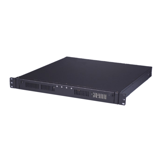
Introduction ACP-1000MB is a compact 1U-high ATX M/B server platform that offers superior per- formance and scalability for customers who want to grow their business without increasing their data center space. It is an ideal server for infrastructure and Web- hosting applications with Advantech Industrial M/B series. -
Page 11: Power Supply Options
° ° ° ° 10 to 85% @ 40 10 to 95% @ 40 ° ° Humidity non-condensing non-condensing Vibration 1 Grms 10 G with 11 ms duration, Shock 30 G half sine wave Safety CE compliant ACP-1000MB User Manual... -
Page 12: Dimension Diagram
Dimension Diagram Unit: mm [inch] Figure 1.1 Dimension diagram ACP-1000MB User Manual... -
Page 13: Chapter 2 System Setup
Chapter System Setup This chapter introduces the instal- lation process. Sections include: ! Installing the Motherboard ! Installing an Add-on Card ! Installing Disk Drives... -
Page 14: Removing The Top Cover
Loosen five screws on the rear and both sides of the top cover. Pull the top cover backwards and then lift it up. Installing the Motherboard The ACP-1000MB can support an ATX motherboard with up to three add-on cards via the expanded riser card. To install the motherboard, please proceed as follows: Note! Use caution when installing a motherboard. -
Page 15: Installing An Add-On Card
Installing an Add-on Card ACP-1000MB supports one add-on card via the riser card. To install the add-on card, please refer to the process is as follows: Remove the I/O bracket attached to the rear plate of the chassis. Insert an add- on card into the slot on the riser card. - Page 16 HDD onto the bracket, then return and fasten the whole kit onto the chassis. Connect the suitable cables from the motherboard to the 3.5" internal HDD, the optical disk drive, or FDD. Then, plug the power connector into each disk drive. ACP-1000MB User Manual...
-
Page 17: Chapter 3 Operation
Chapter Operation This chapter introduces the sys- tem operation information. Sections include: ! The front panel ! Replacing the cooling fan ! Replacing the filter ! Replacing the power supply... -
Page 18: The Front Panel
C). An audible alarm will be activated. To stop the alarm beep, press ° the Alarm Reset button. Inspect the fan filter and the rear section of the chassis immediately. Make sure the airflow inside the chassis is smooth and not blocked by dust or other particles. ACP-1000MB User Manual... -
Page 19: Replacing The Cooling Fan
Replace the power supply with a new one and then fasten it onto the chassis. Plug the ATX power connector to the motherboard. And plug other power con- nectors to the disk drives and peripherals. Return the top cover. Then plug in the power cord. ACP-1000MB User Manual... - Page 20 ACP-1000MB User Manual...
-
Page 21: Chapter 4 Alarm Board
Chapter Alarm Board This chapter introduces the alarm board and thermal sensor specifi- cations. Sections include: ! Alarm Board Layout ! Alarm Board Specifications ! Thermal Sensor ! Sensor I.D. Number Setting... -
Page 22: Alarm Board Layout
To stop the alarm beep, press the Alarm Reset button on the front panel, then take necessary action to remedy the problem condition. Alarm Board Layout The layout and detailed specifications for connectors on the alarm board are shown in this diagram: Figure 4.1 Alarm board layout ACP-1000MB User Manual... -
Page 23: Alarm Board Specifications
Pin 7 -12 V Pin 4 -5 V Pin 8 +12 V Table 4.4: CN16, Power good input connector Pin 1 Power Good Pin 2 Table 4.5: CN17, Alarm reset connector Pin 1 ALARM RESET Pin 2 ACP-1000MB User Manual... - Page 24 Table 4.9: J1, External buzzer Pin 1 Buzzer Pin 2 +5 V Table 4.10: SW1, Fan number select switch Pin 1 Pin 5 Pin 2 FAN_SEL1 Pin 6 FAN_SEL3 Pin 3 Pin 7 Pin 4 FAN_SEL2 Pin 8 RESET ACP-1000MB User Manual...
-
Page 25: Switch Settings
FAN2. If the two fans are connected to other fan connectors, out of sequence, such as FAN1 and FAN3 or FAN2 and FAN3 or FAN3 and FAN4, instead of FAN1 and FAN2, then the alarm will not function cor- rectly. ACP-1000MB User Manual... -
Page 26: Thermal Sensor
Thermal Sensor The ACP-1000MB is configured with a thermal sensor on the backside of the chas- sis. (see Figure 4.2) Thermal sensor Figure 4.2 Thermal sensor location Refer to Figure 4.3 for a diagram of the thermal sensor module layout. - Page 27 Table 4.12: CN1 & CN2, Temperature sensor connector Pin 1 +5 V Pin 3 T_SDAT Pin 2 T_SCLK Pin 4 Table 4.13: SW1, Thermal sensor I.D. setting Sensor I.D. No. SW 1-1 SW 1-2 SW 1-3 SW 1-4 1 (default) ACP-1000MB User Manual...
- Page 28 ACP-1000MB User Manual...
- Page 29 Appendix Exploded Diagram...
- Page 30 Exploded Diagram Figure A.1 Exploded diagram ACP-1000MB User Manual...
- Page 31 Appendix Motherboard Options...
- Page 32 Motherboard Options The ACP-1000MB supports a variety of Advantech ATX motherboards described below. Contact your local sales representative for more detailed information. Table B.1: ATX motherboard options Model Name PCI/ISA SATA 2 (PCI-X 64-bit) AIMB-750 1 (4X) 4 (PCI 32-bit)
- Page 33 ACP-1000MB User Manual...
- Page 34 No part of this publication may be reproduced in any form or by any means, electronic, photocopying, recording or otherwise, without prior written permis- sion of the publisher. All brand and product names are trademarks or registered trademarks of their respective companies. © Advantech Co., Ltd. 2009...
Need help?
Do you have a question about the ACP-1000MB and is the answer not in the manual?
Questions and answers