Planet SGSW-24040 User Manual
Layer 2 managed stackable switch
Hide thumbs
Also See for SGSW-24040:
- User manual (567 pages) ,
- Quick installation manual (12 pages) ,
- User manual (328 pages)
Table of Contents
Advertisement
Quick Links
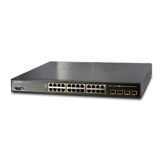
SGSW-24040 / SGSW-24040R
24-Port 10/100/1000Mbps
Layer 2 Managed Stackable Switch
SGSW-24040P / SGSW-24040P4
24G PoE Layer2 Managed Stackable Switch
SGSW-24240 / SGSW-24240R
24-Port 100/1000 SFP Fiber
Layer2 Managed Stackable Switch
SGSW-24040HP
24G High PoE Layer2 Managed Stackable Switch
User's Manual of SGSW-24040 / 24240 Series
User's Manual
1
Advertisement
Table of Contents

Related Manuals for Planet SGSW-24040


Summary of Contents for Planet SGSW-24040
- Page 1 User’s Manual of SGSW-24040 / 24240 Series User’s Manual SGSW-24040 / SGSW-24040R 24-Port 10/100/1000Mbps Layer 2 Managed Stackable Switch SGSW-24040P / SGSW-24040P4 24G PoE Layer2 Managed Stackable Switch SGSW-24240 / SGSW-24240R 24-Port 100/1000 SFP Fiber Layer2 Managed Stackable Switch SGSW-24040HP...
-
Page 2: Fcc Warning
PLANET is a registered trademark of PLANET Technology Corp. All other trademarks belong to their respective owners. Disclaimer PLANET Technology does not warrant that the hardware will work properly in all environments and applications, and makes no warranty and representation, either implied or expressed, with respect to the quality, performance, merchantability, or fitness for a particular purpose. - Page 3 (e.g. use of power strips). Revision PLANET 24-Port 10/100/1000Mbps with 4 Shared SFP / 24 100/1000 SFP Slots with 8 Shared TP Managed Stackable Switch User's Manual FOR MODELS: SGSW-24040 / SGSW-24240 Series REVISION: 1.7 (AUGUST.2012)
-
Page 4: Table Of Contents
User’s Manual of SGSW-24040 / 24240 Series TABLE OF CONETNTS 1. INTRODUTION ........................20 1.1 Packet Contents ............................20 1.2 Product Description .............................1 1.3 How to Use This Manual ..........................2 1.4 Product Features............................3 1.5 Product Specification ..........................6 2. INSTALLATION ........................14 2.1 Hardware Description ..........................14... - Page 5 User’s Manual of SGSW-24040 / 24240 Series 4.2.1 System Information..............................45 4.2.2 IP Configuration ..............................46 4.2.3 IPv6 Configuration ...............................47 4.2.4 Users Configuration .............................48 4.2.5 Users Privilege Levels ............................51 4.2.6 NTP Configuration ...............................53 4.2.7 UPnP Configuration .............................54 4.2.8 DHCP Relay ................................55 4.2.9 DHCP Relay Statistics ............................57 4.2.10 CPU Load ................................59...
- Page 6 User’s Manual of SGSW-24040 / 24240 Series 4.5.2 LACP Configuration .............................97 4.5.3 LACP System Status ............................98 4.5.4 LACP Port Status..............................99 4.5.5 LACP Port Statistics............................101 4.6 VLAN................................102 4.6.1 VLAN Overview ..............................102 4.6.2 IEEE 802.1Q VLAN ............................102 4.6.3 VLAN Basic Information.............................106 4.6.4 VLAN Port Configuration ...........................107 4.6.5 VLAN Membership Configuration ........................
- Page 7 User’s Manual of SGSW-24040 / 24240 Series 4.9.1 Understand QOS ...............................161 4.9.2 QCL Configuration Wizard ..........................162 4.9.2.1 Set up Policy Rules ..........................163 4.9.2.2 Set up Typical Network Application Rules ....................164 4.9.2.3 Set up ToS Precedence Mapping ......................166 4.9.2.4 Set up VLAN Tag Priority Mapping ......................168 4.9.3 QoS Control List Configuration ..........................169...
- Page 8 User’s Manual of SGSW-24040 / 24240 Series 4.12.7 Port Security Detail ............................251 4.12.8 DHCP Snooping ..............................252 4.12.9 DHCP Snooping Statistics ..........................253 4.12.10 IP Source Guard Configuration........................255 4.12.11 IP Source Guard Static Table .........................257 4.12.12 ARP Inspection ..............................258 4.12.13 ARP Inspection Static Table ...........................259 4.13 Address Table ............................261...
- Page 9 User’s Manual of SGSW-24040 / 24240 Series 4.17.1.4 Shortest Path Forwarding ........................308 4.17.2 Stack Configuration ............................309 4.17.3 Stack Information .............................312 4.17.4 Stack Port State Ovewview..........................313 4.17.5 Stack Example..............................313 5. COMMAND LINE INTERFACE..................317 5.1 Accessing the CLI ............................317 Logon to the Console ............................317 Configure IP address............................318...
- Page 10 User’s Manual of SGSW-24040 / 24240 Series IP DNS Proxy ..............................335 IPv6 AUTOCINFIG ..............................335 IPv6 Setup................................336 IPv6 Ping ................................336 IP NTP Configuration............................337 IP NTP Mode ...............................338 IP NTP Server Add ..............................338 IP NTP Server IPv6 Add ............................339 IP NTP Server Delete ............................339 6.4 Port Management Command........................340...
- Page 11 User’s Manual of SGSW-24040 / 24240 Series VLAN Add................................356 VLAN Delete................................357 VLAN Lookup ..............................357 VLAN Status ................................358 6.7 Private VLAN Configuration Command ....................360 PVLAN Configuration ............................360 PVLAN Add .................................361 PVLAN Delete ..............................361 PVLAN Lookup..............................362 PVLAN Isolate ..............................362 6.8 Security Command...........................364 Security Switch User Configuration ........................364...
- Page 12 User’s Manual of SGSW-24040 / 24240 Series Security Switch SNMP Trap Community ......................380 Security Switch SNMP Trap Destination......................381 Security Switch SNMP Trap IPv6 Destination .....................381 Security Switch SNMP Trap Authentication Failure .....................382 Security Switch SNMP Trap Link-up........................382 Security Switch SNMP Trap Inform Mode ......................383 Security Switch SNMP Trap Inform Timeout......................384...
- Page 13 User’s Manual of SGSW-24040 / 24240 Series Security Network NAS State..........................403 Security Network NAS Reauthentication ......................404 Security Network NAS ReauthPeriod ........................404 Security Network NAS EapolTimeout ........................405 Security Network NAS Agetime ...........................405 Security Network NAS Holdtime..........................406 Security Network NAS RADIUS_QoS .........................406 Security Network NAS RADIUS_VLAN .......................407...
- Page 14 User’s Manual of SGSW-24040 / 24240 Series Security Network ARP Inspection Status ......................429 Security AAA Configuration ..........................429 Security AAA Timeout ............................430 Security AAA Deadtime ............................431 Security AAA RADIUS ............................431 Security AAA ACCT_RADIUS..........................432 Security AAA TACACS+ ............................433 Security AAA Statistics............................433 6.9 Spanning Tree Protocol Command ......................435 STP Configuration ...............................435...
- Page 15 User’s Manual of SGSW-24040 / 24240 Series IGMP Leave Proxy ..............................451 IGMP State ................................451 IGMP Querier ..............................452 IGMP Fastleave..............................452 IGMP Throttling ..............................453 IGMP Filtering ..............................453 IGMP Router ...............................454 IGMP Flooding ..............................455 IGMP Groups...............................455 IGMP Status ................................455 6.11 Link Aggregation Command .........................457 Aggregation Configuration...........................457...
- Page 16 User’s Manual of SGSW-24040 / 24240 Series LLDPMED Policy Delete............................472 LLDPMED Policy Add............................472 LLDPMED Port Policy ............................473 LLDPMED Coordinates ............................474 LLDPMED Datum..............................474 LLDPMED Fast ..............................475 LLDPMED Info ..............................475 LLDPMED Debuge_med_transmit_var .......................475 6.15 Power over Ethernet Command......................476 PoE Configuration ...............................476 PoE Mode................................477 PoE Priority .................................477...
- Page 17 User’s Manual of SGSW-24040 / 24240 Series Mirror Mode .................................491 6.18 Configuration Command ........................493 Configuration Save..............................493 Configuration Load ..............................493 6.19 Firmware Command..........................494 Firmware Load ..............................494 Firmware IPv6 Load ............................494 6.20 UPnP Command .............................495 UPnP Configuration.............................495 UPnP Mode .................................495 UPnP TTL................................496 UPnP Advertising Duration ..........................496...
- Page 18 User’s Manual of SGSW-24040 / 24240 Series SMTP Auth ................................510 SMTP Auth_user ..............................510 SMTP Auth_pass..............................511 SMTP Mailfrom..............................511 SMTP Mailsubject..............................511 SMTP Mailto1..............................512 SMTP Mailto2..............................512 6.24 Show Command .............................513 Show ACL Configuration .............................513 Show Link Aggregation Configuration .........................513 Show IGMP Configuration ...........................513 Show IP Configuration............................513...
- Page 19 User’s Manual of SGSW-24040 / 24240 Series Stages of powering up a PoE link ..........................521 Line Detection................................521 Classification ................................522 Start-up ..................................522 Operation..................................522 Power Disconnection Scenarios ..........................522 9. TROUBLE SHOOTING...................... 524 APPENDEX A ........................526 A.1 Switch's RJ-45 Pin Assignments ......................526 A.2 10/100Mbps, 10/100Base-TX ........................526...
-
Page 20: Introdution
1. INTRODUTION The PLANET Layer 2 Managed Gigabit Switch series –SGSW Stackable, SGSW PoE and SGSW Fiber switch are all multiple ports Gigabit Ethernet Switched with SFP fiber optical connective ability and robust layer 2 features; the description of these... -
Page 21: Product Description
High-Performance / Cost-effective / Telecom class Gigabit solution for Enterprise backbone and Data Center Networking The PLANET Managed Switch is a L2/L4 Managed Gigabit Switch. Since Gigabit network interface had become the basic equipment and requirement of Enterprise and Network Servers, with 48Gbps switching fabric, the Managed Switch can handle extremely large amounts of data in a secure topology linking to a backbone or high capacity servers. - Page 22 Advanced Features and Centralized Power Management for Enterprise and Campus PoE Networking (PoE Model) The PLANET SGSW-24040P series PoE Switch provides 24 10/100/1000Mbps Power-over-Ethernet (PoE, IEEE 802.3af compliant) ports which optimize the installation and power management of network devices such as wireless access points (AP), Voice over IP (VoIP) phones, and security video cameras.
-
Page 23: How To Use This Manual
User’s Manual of SGSW-24040 / 24240 Series reduces installation time. IEEE 802.3at Power over Ethernet Pre-Standard Compliant (SGSW-24040HP only) Till today, the IEEE 802.3af Power over Ethernet Standard has become popular yet the PoE demand still grows for increasing network-powered applications. With many critical applications appears, the IEEE 802.3af PoE standard may not afford the trend of higher power demand. -
Page 24: Product Features
User’s Manual of SGSW-24040 / 24240 Series 1.4 Product Features Physical Port SGSW-24040 / SGSW-24040R 24-Port 10/100/1000Base-T Gigabit Ethernet RJ-45 4 100/1000Base-X SFP slots, shared with Port-21 to Port-24 RS-232 DB9 console interface for Switch basic management and setup ... - Page 25 User’s Manual of SGSW-24040 / 24240 Series 802.3ad Link Aggregation Control Protocol (LACP) Cisco ether-channel (Static Trunk) Maximum 12 trunk groups, up to 16 ports per trunk group Up to 16Gbps bandwidth(Duplex Mode) ■ Provide Port Mirror (many-to-1) ■...
- Page 26 User’s Manual of SGSW-24040 / 24240 Series Management ■ Switch Management Interfaces Console / Telnet Command Line Interface Web switch management SNMP v1, v2c, and v3 switch management SSH / SSL secure access ■ Four RMON groups (history, statistics, alarms, and events) ■...
-
Page 27: Product Specification
IEEE 802.3x Pause Frame for Full-Duplex Flow Control Back pressure for Half-Duplex 10Kbytes Jumbo Frame < 5 seconds: System reboot Reset Button > 10 seconds: Factory Default 440 x 200 x 44.5 mm, 1U high Dimension (W x D x H) SGSW-24040: 3.0kg Weight... - Page 28 User’s Manual of SGSW-24040 / 24240 Series SGSW-24040R: 3.1kg Power, Link/Act and speed per Gigabit port Max. 30.2 watts / 102.98 BTU Power Consumption AC 100~240V, 50/60Hz AC 100~240V, 50/60Hz Power Requirement – AC -48V DC @ 0.6A Power Requirement – DC...
- Page 29 User’s Manual of SGSW-24040 / 24240 Series RFC-1493 Bridge MIB RFC-1643 Ethernet MIB RFC-2863 Interface MIB RFC-2665 Ether-Like MIB RFC-2737 Entity MIB RFC-2618 RADIUS Client MIB RFC-2933 IGMP-STD-MIB RFC3411 SNMP-Frameworks-MIB IEEE 802.1X PAE LLDP MAU-MIB Standards Conformance FCC Part 15 Class A, CE Regulation Compliance IEEE 802.3 10Base-T...
- Page 30 User’s Manual of SGSW-24040 / 24240 Series 1392 kilobytes Share data Buffer Store-and-Forward Switch Processing Scheme IEEE 802.3x Pause Frame for Full-Duplex Flow Control Back pressure for Half-Duplex 10Kbytes Jumbo Frame < 5 seconds: System reboot Reset Button > 10 seconds: Factory Default 440 x 200 x 44.5 mm, 1U high...
- Page 31 User’s Manual of SGSW-24040 / 24240 Series - Port Number - 802.1p priority - DS/TOS field in IP Packet IGMP (v1/v2) Snooping, up to 255 multicast Groups IGMP Snooping IGMP Querier mode support IP-Based ACL / MAC-Based ACL Access Control List...
- Page 32 SGSW Stackable PoE models Product SGSW-24040P SGSW-24040P4 SGSW-24040HP Hardware Specification 24 10/ 100/1000Base-T RJ-45 Auto-MDI/MDI-X ports Copper Ports 4 SFP interfaces, shared with Port-21 to Port-24 SFP/mini-GBIC Slots 1 x RS-232 DB9 serial port (115200, 8, N, 1) Console Port 2 5GbE / Cross-HDMI interface Stacking Ports 68Gbps / non-blocking...
- Page 33 User’s Manual of SGSW-24040 / 24240 Series Number of PD @ 15.4Watts Number of PD @ 30.8Watts Layer 2 Function Console, Telnet, Web Browser, SNMPv1, v2c and v3 Basic Management Interfaces SSH, SSL, SNMP v3 Secure Management Interface Port disable/enable.
- Page 34 User’s Manual of SGSW-24040 / 24240 Series RFC3411 SNMP-Frameworks-MIB IEEE 802.1X PAE LLDP MAU-MIB Standards Conformance FCC Part 15 Class A, CE Regulation Compliance IEEE 802.3 10Base-T IEEE 802.3u 100Base-TX/100Base-FX IEEE 802.3z Gigabit SX/LX IEEE 802.3ab Gigabit 1000T IEEE 802.3x Flow Control and Back pressure IEEE 802.3ad Port trunk with LACP...
-
Page 35: Installation
User’s Manual of SGSW-24040 / 24240 Series 2. INSTALLATION This section describes the hardware features and installation of the Managed Switch on the desktop or rack mount. For easier management and control of the Managed Switch, familiarize yourself with its display indicators, and ports. Front panel illustrations in this chapter display the unit LED indicators. - Page 36 User’s Manual of SGSW-24040 / 24240 Series ■ Gigabit TP interface 10/100/1000Base-T Copper, RJ-45 Twist-Pair: Up to 100 meters. ■ Gigabit SFP slots 1000Base-SX/LX mini-GBIC slot, SFP (Small Factor Pluggable) transceiver module: From 550 meters (Multi-mode fiber), up to 10/30/50/70/120 kilometers (Single-mode fiber).
-
Page 37: Led Indications
User’s Manual of SGSW-24040 / 24240 Series 2.1.2 LED Indications The front panel LEDs indicates instant status of port links, data activity and system power; helps monitor and troubleshoot when needed. Figure 2-5 & Figure 2-7 shows the LED indications of these Managed Switches. - Page 38 User’s Manual of SGSW-24040 / 24240 Series ■ 1000Base-SX/LX SFP interfaces (Shared Port-21~Port-24) Color Function Lights: To indicate the link through that SFP port is successfully established with 1000 speed 1000Mbps Green To indicate that the SFP port is link down...
- Page 39 User’s Manual of SGSW-24040 / 24240 Series ■ 10/100/1000Base-T interfaces Color Function Lights: To indicate the link through that port is successfully established with speed 10Mbps or 100Mbps or 1000Mbps Blink: To indicate that the switch is actively sending or receiving data over that port.
- Page 40 User’s Manual of SGSW-24040 / 24240 Series Lights to indicate the stacking link through that port is successfully established. STX1 Green Lights to indicate the stacking link through that port is successfully established. STX2 Green ■ 10/100/1000Base-T interfaces (Shared Port-1~Port-8)
-
Page 41: Switch Rear Panel
User’s Manual of SGSW-24040 / 24240 Series 2.1.3 Switch Rear Panel The rear panel of the Managed Switch indicates an AC inlet power socket, which accepts input power from 100 to 240V AC, 50-60Hz. Figure 2-8 & Figure 2-12 shows the rear panel of these Managed Switches... - Page 42 STX2 / Cascade UP port should connect to other switch’s STX1 / Cascade Down out. You can just use attached PLANET CB-STX50 or longer stack cable CB-STX200 connector to stack. The CB-STX50 and CB-STX200 are Cross-Overed HDMI cables; only attached PLANET stack cable can be used. Plug-and-play connection.
- Page 43 User’s Manual of SGSW-24040 / 24240 Series Figure 2-14 SGSW-24040 /24040R Series Stack Ports...
-
Page 44: Install The Switch
User’s Manual of SGSW-24040 / 24240 Series 2.2 Install the Switch This section describes how to install your Managed Switch and make connections to the Managed Switch. Please read the following topics and perform the procedures in the order being presented. To install your Managed Switch on a desktop or shelf, simply complete the following steps. -
Page 45: Rack Mounting
User’s Manual of SGSW-24040 / 24240 Series Supply power to the Managed Switch. Step5: Connect one end of the power cable to the Managed Switch. Connect the power plug of the power cable to a standard wall outlet. When the Managed Switch receives power, the Power LED should remain solid Green. -
Page 46: Installing The Sfp Transceiver
User’s Manual of SGSW-24040 / 24240 Series Figure 2-17 Mounting SGSW-24040 in a Rack Step6: Proceeds with the steps 4 and steps 5 of session 2.2.1 Desktop Installation to connect the network cabling and supply power to the Managed Switch. - Page 47 Approved PLANET SFP Transceivers PLANET Managed Switch supports both Single mode and Multi-mode SFP transceiver. The following list of approved PLANET SFP transceivers is correct at the time of publication: ■ MGB-SX SFP (1000BASE-SX SFP transceiver / Multi-mode / 850nm / 220m~550m) ■...
-
Page 48: Connecting Dc Power Supply
User’s Manual of SGSW-24040 / 24240 Series Figure 2-19 Pull out the SFP transceiver Never pull out the module without pull the handle or the push bolts on the module. Direct pull out the module with violent could damage the module and SFP module slot of the Managed Switch. - Page 49 User’s Manual of SGSW-24040 / 24240 Series Before connect the DC power cable to the input terminal block of Managed Switch, ensure that the Warning: power switch in the “OFF” position and the DC power is OFF...
-
Page 50: Stack Installation
SGSW-24040 / 24240 Series The SGSW-24040 / 24240 series Managed Switch provides a switch stacking function to manage up to 16 switches using a single IP address. And up to 384 Gigabit Ethernet ports can be managed by a stacking group and you can add ports and functionality as needed. -
Page 51: Connecting Stacking Cable
There are two high-performance HDMI-like Stack ports on the rear panel for proprietary management stack. Only attached PLANET CB-STX50 and CB-STX200 cross-overed HDMI cable can be used. STEP-1: Plug one end of the cable in the “STX1 / Cascade Down” port and the other end to the ”STX2 / Cascade UP” port of next device. - Page 52 STEP-7: Connect the RS-232 serial cable to the console port on the front of the stack master, then loin the SGSW Switch to start the switch management. Or you can use the PLANET Smart Discovery Utility to displayt the IP address of the stack and Web login the stack with this IP address.
- Page 53 (console, telnet, web and SNMP) is accessible. It’s allow to build a stack of up to 16 PLANET SGSW Switches. If there is the space limitation or power issue and you wish to stack all the switches in different racks, use long stack cables “CB-STX200” to connect two stacks.
-
Page 54: Switch Management
User’s Manual of SGSW-24040 / 24240 Series 3. SWITCH MANAGEMENT This chapter explains the methods that you can use to configure management access to the Managed Switch. It describes the types of management applications and the communication and management protocols that deliver data between your management device (workstation or personal computer) and the system. -
Page 55: Management Access Overview
User’s Manual of SGSW-24040 / 24240 Series 3.2 Management Access Overview The Managed Switch gives you the flexibility to access and manage it using any or all of the following methods: An administration console Web browser interface ... - Page 56 User’s Manual of SGSW-24040 / 24240 Series Figure 3-1 Console management Direct Access Direct access to the administration console is achieved by directly connecting a terminal or a PC equipped with a terminal-emulation program (such as HyperTerminal) to the Managed Switch console (serial) port.
-
Page 57: Web Management
User’s Manual of SGSW-24040 / 24240 Series 3.4 Web Management The Managed Switch offers management features that allow users to manage the Managed Switch from anywhere on the network through a standard browser such as Microsoft Internet Explorer. After you set up your IP address for the switch, you can access the Managed Switch's Web interface applications directly in your Web browser by entering the IP address of the Managed Switch. - Page 58 User’s Manual of SGSW-24040 / 24240 Series...
-
Page 59: Snmp-Based Network Management
User’s Manual of SGSW-24040 / 24240 Series 3.5 SNMP-Based Network Management You can use an external SNMP-based application to configure and manage the Managed Switch, such as SNMPc Network Manager, HP Openview Network Node Management (NNM) or What’s Up Gold. This management method requires the SNMP agent on the switch and the SNMP Network Management Station to use the same community string. -
Page 60: Web Configuration
User’s Manual of SGSW-24040 / 24240 Series 4. WEB CONFIGURATION This section introduces the configuration and functions of the Web-Based management. About Web-based Management The Managed Switch offers management features that allow users to manage the Managed Switch from anywhere on the network through a standard browser such as Microsoft Internet Explorer. - Page 61 User’s Manual of SGSW-24040 / 24240 Series Logging on the switch Use Internet Explorer 7.0 or above Web browser. Enter the factory-default IP address to access the Web interface. The factory-default IP Address as following: http://192.168.0.100 When the following login screen appears, please enter the default username "admin" with password “admin” (or the username/password you have changed via console) to login the main screen of Managed Switch.
- Page 62 User’s Manual of SGSW-24040 / 24240 Series Figure 4-1-3 Default main page Now, you can use the Web management interface to continue the switch management or manage the Managed Switch by Web interface. The Switch Menu on the left of the web page let you access all the commands and statistics the Managed Switch provides.
-
Page 63: Main Web
User’s Manual of SGSW-24040 / 24240 Series 4.1 Main Web Page The SGSW Managed Switch provides a Web-based browser interface for configuring and managing it. This interface allows you to access the Managed Switch using the Web browser of your choice. This chapter describes how to use the Managed Switch’s Web browser interface to configure and manage it. - Page 64 User’s Manual of SGSW-24040 / 24240 Series Figure 4-1-5 SGSW Managed Switch Main Functions Menu...
-
Page 65: System
User’s Manual of SGSW-24040 / 24240 Series 4.2 System Use the System menu items to display and configure basic administrative details of the Managed Switch. Under System the following topics are provided to configure and view the system information: This section has the following items: The switch system information is provided here. -
Page 66: System Information
User’s Manual of SGSW-24040 / 24240 Series 4.2.1 System Information The System Info page provides information for the current device information. System Info page helps a switch administrator to identify the hardware MAC address, software version and system uptime. The screen in Figure 4-2-1 appears. -
Page 67: Ip Configuration
User’s Manual of SGSW-24040 / 24240 Series Buttons Auto-refresh : Check this box to enable an automatic refresh of the page at regular intervals. : Click to refresh the page; any changes made locally will be undone. 4.2.2 IP Configuration The IP Configuration includes the IP Address, Subnet Mask and Gateway. -
Page 68: Ipv6 Configuration
User’s Manual of SGSW-24040 / 24240 Series VLAN ID Provide the managed VLAN ID. The allowed range is 1 through 4095. DNS Server Provide the IP address of the DNS Server in dotted decimal notation. DNS Proxy... -
Page 69: Users Configuration
User’s Manual of SGSW-24040 / 24240 Series represented as eight fields of up to four hexadecimal digits with a colon separates each field (:). For example, 'fe80::215:c5ff:fe03:4dc7'. The symbol '::' is a special syntax that can be used as a shorthand way of representing multiple 16-bit groups of contiguous zeros;... - Page 70 User’s Manual of SGSW-24040 / 24240 Series The page includes the following fields: Object Description Username The name identifying the user. This is also a link to Add/Edit User. The privilgeg level for the user. Privilege Level Buttons : Click to add a new user.
- Page 71 User’s Manual of SGSW-24040 / 24240 Series Once the new user is added, the new user entry shown in the Users Configuration page. Figure 4-2-6 User Configuration page screenshot After change the default password, if you forget the password. Please press the “Reset” button in the front panel of the Managed Switch over 10 seconds and then release, the current setting includes VLAN, will be lost and the Managed Switch will restore to the default mode.
-
Page 72: Users Privilege Levels
User’s Manual of SGSW-24040 / 24240 Series 4.2.5 Users Privilege Levels This page provides an overview of the privilege levels. After setup completed, please press “Save” button to take effect. Please login web interface with new user name and password, the screen in Figure 4-2-7 appears. - Page 73 User’s Manual of SGSW-24040 / 24240 Series contains more than one. The following description defines these privilege level groups in details: System: Contact, Name, Location, Timezone, Log. Security: Authentication, System Access Management, Port (contains Dot1x port, MAC based and the MAC Address Limit), ACL, HTTPS, SSH, ARP Inspection and IP source guard.
-
Page 74: Ntp Configuration
User’s Manual of SGSW-24040 / 24240 Series 4.2.6 NTP Configuration Configure NTP on this page. NTP is an acronym for Network Time Protocol, a network protocol for synchronizing the clocks of computer systems. NTP uses UDP (data grams) as transport layer. You can specify NTP Servers and set GMT Time zone. The NTP Configuration... -
Page 75: Upnp Configuration
User’s Manual of SGSW-24040 / 24240 Series 4.2.7 UPnP Configuration Configure UPnP on this page. UPnP is an acronym for Universal Plug and Play. The goals of UPnP are to allow devices to connect seamlessly and to simplify the implementation of networks in the home (data sharing, communications, and entertainment) and in corporate environments for simplified installation of computer components. -
Page 76: Dhcp Relay
User’s Manual of SGSW-24040 / 24240 Series Buttons : Click to save changes. : Click to undo any changes made locally and revert to previously saved values. Figure 4-2-10 UPnP devices shows on Windows My Network Places 4.2.8 DHCP Relay Configure DHCP Relay on this page. - Page 77 User’s Manual of SGSW-24040 / 24240 Series The definition of Circuit ID in the switch is 4 bytes in length and the format is "vlan_id" "module_id" "port_no". The parameter of "vlan_id" is the first two bytes represent the VLAN ID. The parameter of "module_id" is the third byte for the module ID (in standalone switch it always equal 0, in stackable switch it means switch ID).
-
Page 78: Dhcp Relay Statistics
User’s Manual of SGSW-24040 / 24240 Series DHCP relay information operation mode enabled. Possible policies are: Replace: Replace the original relay information when receive a DHCP message that already contains it. Keep: Keep the original relay information when receive a DHCP message that already contains it. - Page 79 User’s Manual of SGSW-24040 / 24240 Series Receive Missing The packets number that received packets which Remote ID option was missing. Remote ID Receive Bad Circuit ID The packets number that the Circuit ID option did not match known circuit ID.
-
Page 80: Cpu Load
User’s Manual of SGSW-24040 / 24240 Series 4.2.10 CPU Load This page displays the CPU load, using a SVG graph. The load is measured as averaged over the last 100ms, 1sec and 10 seconds intervals. The last 120 samles are graphed, and the last numbers are displayed as text as well. -
Page 81: System Log
User’s Manual of SGSW-24040 / 24240 Series 4.2.11 System Log The switch system log information is provided here. The System Log screen in Figure 4-2-14 appears. Figure 4-2-14 System Log page screenshot The page includes the following fields: Object Description ... -
Page 82: Detailed Log
User’s Manual of SGSW-24040 / 24240 Series : Updates the system log entries, starting from the last entry currently displayed. : Updates the system log entries, ending at the last available entry ID. 4.2.12 Detailed Log The switch system detailed log information is provided here. The Detailed Log screen in Figure 4-2-15 appears. -
Page 83: Remote Syslog
User’s Manual of SGSW-24040 / 24240 Series 4.2.13 Remote Syslog Configure remote syslog on this page. The Remote Syslog screen in Figure 4-2-16 appears. Figure 4-2-16 Remote Syslog page screenshot The page includes the following fields: Object Description Mode Indicates the remote syslog mode operation. -
Page 84: Smtp Configure
User’s Manual of SGSW-24040 / 24240 Series 4.2.14 SMTP Configure This page facilitates a SMTP Configure the switch. The SMTP Configure screen in Figure 4-2-17 appears. Figure 4-2-17 SMTP Configuration page screenshot The page includes the following fields: Object Description ... -
Page 85: Web Firmware Upgrade
User’s Manual of SGSW-24040 / 24240 Series Buttons : Send a test mail to mail server to check this account is available or not. : Click to save changes. : Click to undo any changes made locally and revert to previously saved values. -
Page 86: Tftp Firmware Upgrade
User’s Manual of SGSW-24040 / 24240 Series the Managed Switch until the update progress is complete. DO NOT Power OFF Do not quit the Firmware Upgrade page without press the “OK” button - after the image be loaded. Or the system won’t apply the new firmware. User has to repeat the firmware upgrade processes again. -
Page 87: Configuration Backup
User’s Manual of SGSW-24040 / 24240 Series 4.2.17 Configuration Backup This function allows backup and reload the current configuration of the Managed Switch to the local management station. The Configuration Backup screen in Figure 4-2-21 appears. Figure 4-2-21 Configuration Backup page screenshot You can save/view or load the switch configuration. - Page 88 User’s Manual of SGSW-24040 / 24240 Series Figure 4-2-22 File Download screen Chose the file save path in management workstation. Figure 4-2-23 File save screen...
-
Page 89: Configuration Upload
User’s Manual of SGSW-24040 / 24240 Series 4.2.18 Configuration Upload This function allows backup and reload the current configuration of the Managed Switch to the local management station. The Configuration Upload screen in Figure 4-2-24 appears. Figure 4-2-24 Configuration Upload page screenshot ... -
Page 90: Factory Default
User’s Manual of SGSW-24040 / 24240 Series 4.2.19 Factory Default You can reset the configuration of the stack switch on this page. Only the IP configuration is retained. The new configuration is available immediately, which means that no restart is necessary. The Factory Default screen in Figure 4-2-26 appears. -
Page 91: System Reboot
User’s Manual of SGSW-24040 / 24240 Series 4.2.20 System Reboot The Reboot page enables the device to be rebooted from a remote location. Once the Reboot button is pressed, user have to re-login the WEB interface about 60 seconds later, the System Reboot screen in Figure 4-2-27 appears. -
Page 92: Simple Network Management Protocol
User’s Manual of SGSW-24040 / 24240 Series 4.3 Simple Network Management Protocol 4.3.1 SNMP Overview The Simple Network Management Protocol (SNMP) is an application layer protocol that facilitates the exchange of management information between network devices. It is part of the Transmission Control Protocol/Internet Protocol (TCP/IP) protocol suite. -
Page 93: Snmp System Configuration
User’s Manual of SGSW-24040 / 24240 Series Configure SNMPv3 communities table on this page. SNMPv3 Communities Configure SNMPv3 users table on this page. SNMPv3 Users Configure SNMPv3 groups table on this page. SNMPv3 Groups Configure SNMPv3 views table on this page. -
Page 94: Snmp System Information Configuration
User’s Manual of SGSW-24040 / 24240 Series will associated with SNMPv3 communities table. Indicates the SNMPv3 engine ID. The string must contain an even number Engine ID between 10 and 64 hexadecimal digits, but all-zeros and all-'F's are not allowed. -
Page 95: Snmp Trap Configuration
User’s Manual of SGSW-24040 / 24240 Series to 126. Buttons : Click to save changes. : Click to undo any changes made locally and revert to previously saved values. 4.3.4 SNMP Trap Configuration Configure SNMP trap on this page. The SNMP Trap Configuration screen in Figure 4-3-3 appears. - Page 96 User’s Manual of SGSW-24040 / 24240 Series allowed string length is 0 to 255, and the allowed content is the ASCII characters from 33 to 126. Indicates the SNMP trap destination address. Trap Destination Address Trap Destination IPv6 Provide the trap destination IPv6 address of this switch.
-
Page 97: Snmpv3 Configuration
User’s Manual of SGSW-24040 / 24240 Series 4.3.5 SNMPv3 Configuration 4.3.5.1 SNMPv3 Communities Configuration Configure SNMPv3 communities table on this page. The entry index key is Community. The SNMPv3 Communities Configuration screen in Figure 4-3-4 appears. Figure 4-3-4 SNMPv3 Communities Configuration page screenshot... -
Page 98: Snmpv3 Users Configuration
User’s Manual of SGSW-24040 / 24240 Series 4.3.5.2 SNMPv3 Users Configuration Configure SNMPv3 users table on this page. The entry index key are Engine ID and User Name. The SNMPv3 Users Configuration screen in Figure 4-3-5 appears. Figure 4-3-5 SNMPv3 Users Configuration page screenshot... - Page 99 User’s Manual of SGSW-24040 / 24240 Series 33 to 126. Privacy Protocol Indicates the privacy protocol that this entry should belong to. Possible privacy protocol are: None: None privacy protocol. DES: An optional flag to indicate that this user using DES authentication protocol.
-
Page 100: Snmpv3 Groups Configuration
User’s Manual of SGSW-24040 / 24240 Series 4.3.5.3 SNMPv3 Groups Configuration Configure SNMPv3 groups table on this page. The entry index keys are Security Model and Security Name. The SNMPv3 Groups Configuration screen in Figure 4-3-6 appears. Figure 4-3-6 SNMPv3 Groups Configuration page screenshot... -
Page 101: Snmpv3 Views Configuration
User’s Manual of SGSW-24040 / 24240 Series 4.3.5.4 SNMPv3 Views Configuration Configure SNMPv3 views table on this page. The entry index key are View Name and OID Subtree. The SNMPv3 Views Configuration screen in Figure 4-3-7 appears. Figure 4-3-7 SNMPv3 Views Configuration page screenshot... -
Page 102: Snmpv3 Accesses Configuration
User’s Manual of SGSW-24040 / 24240 Series 4.3.5.5 SNMPv3 Accesses Configuration Configure SNMPv3 accesses table on this page. The entry index key are Group Name, Security Model and Security Level. The SNMPv3 Accesses Configuration screen in Figure 4-3-8 appears. Figure 4-3-8 SNMPv3 Accesses Configuration page screenshot... - Page 103 User’s Manual of SGSW-24040 / 24240 Series Buttons : Click to add a new access entry. : Click to save changes. : Click to undo any changes made locally and revert to previously saved values.
-
Page 104: Port Management
User’s Manual of SGSW-24040 / 24240 Series 4.4 Port Management Use the Port Menu to display or configure the Managed Switch's ports. This section has the following items: Configures port connection settings Port Configuration Port Statistics Overview Lists Ethernet and RMON port statistics ... - Page 105 User’s Manual of SGSW-24040 / 24240 Series Description Indicates the per port description. The current link state is displayed graphically. Green indicates the link is up and Link red that it is down. Provides the current link speed of the port.
-
Page 106: Port Statistics Overview
User’s Manual of SGSW-24040 / 24240 Series Buttons : Click to save changes. : Click to undo any changes made locally and revert to previously saved values. : Click to refresh the page. Any changes made locally will be undone. -
Page 107: Port Statistics Detail
User’s Manual of SGSW-24040 / 24240 Series The displayed counters are: Object Description The logical port for the settings contained in the same row. Port The number of received and transmitted packets per port. Packets The number of received and transmitted bytes per port. - Page 108 User’s Manual of SGSW-24040 / 24240 Series The page includes the following fields: Receive Total and Transmit Total Object Description The number of received and transmitted (good and bad) packets Rx and Tx Packets The number of received and transmitted (good and bad) bytes. Includes FCS, but Rx and Tx Octets excludes framing bits.
-
Page 109: Sfp Module Information
User’s Manual of SGSW-24040 / 24240 Series Transmit Error Counters Object Description The number of frames dropped due to output buffer congestion. Tx Drops The number of frames dropped due to excessive or late collisions. Tx Late/Exc. Coll. - Page 110 User’s Manual of SGSW-24040 / 24240 Series Speed Display the spedd of current SFP module, the speed value or description is get from the SFP module. Different vendors SFP modules might shows different speed information. Wave Length(nm) Display the wavelength of current SFP module, the wavelength value is get from the SFP module.
-
Page 111: Port Mirroring Configuration
User’s Manual of SGSW-24040 / 24240 Series 4.4.5 Port Mirroring Configuration Configure port Mirroring on this page. This function provide to monitoring network traffic that forwards a copy of each incoming or outgoing packet from one port of a network Switch to another port where the packet can be studied. It enables the manager to keep close track of switch performance and alter it if necessary. - Page 112 User’s Manual of SGSW-24040 / 24240 Series Mirror Port Configuration The Port Mirror Configuration screen in Figure 4-4-6 appears. Figure 4-4-6 Port Mirror Configuration page screenshot The page includes the following fields: Object Description Port to mirror to Frames from ports that have either source or destination mirroring enabled are mirrored...
- Page 113 User’s Manual of SGSW-24040 / 24240 Series Switch to mirror to Frames from ports that have either source (rx) or destination (tx) mirroring enabled are mirrored to this switch. The logical port for the settings contained in the same row.
-
Page 114: Link Aggregation
User’s Manual of SGSW-24040 / 24240 Series 4.5 Link Aggregation Port Aggregation optimizes port usage by linking a group of ports together to form a single Link Aggregated Groups (LAGs). Port Aggregation multiplies the bandwidth between the devices, increases port flexibility, and provides link redundancy. - Page 115 User’s Manual of SGSW-24040 / 24240 Series The Link Aggregation Control Protocol (LACP) provides a standardized means for exchanging information between Partner Systems that require high speed redundant links. Link aggregation lets you group up to eight consecutive ports into a single dedicated connection.
-
Page 116: Static Aggregation Configuration
User’s Manual of SGSW-24040 / 24240 Series 4.5.1 Static Aggregation Configuration This page is used to configure the Aggregation hash mode and the aggregation group. The aggregation hash mode settings are global, whereas the aggregation group relate to the currently selected stack unit, as reflected by the page header. - Page 117 User’s Manual of SGSW-24040 / 24240 Series Figure 4-5-3 Aggregation Group Configuration page screenshot The page includes the following fields: .Object Description Indicates the aggregation group type. This field is only valid for stackable Locality switches. Global: The group members may reside on different units in the ...
-
Page 118: Lacp Configuration
User’s Manual of SGSW-24040 / 24240 Series 4.5.2 LACP Configuration Link Aggregation Control Protocol (LACP) - LACP LAG negotiate Aggregated Port links with other LACP ports located on a different device. LACP allows switches connected to each other to discover automatically whether any ports are member of the same LAG. -
Page 119: Lacp System Status
User’s Manual of SGSW-24040 / 24240 Series The page includes the following fields: Object Description The switch port number. Port Controls whether LACP is enabled on this switch port. LACP will form an LACP Enabled aggregation when 2 or more ports are connected to the same partner. LACP can form max 12 LLAGs per switch and 2 GLAGs per stack. -
Page 120: Lacp Port Status
User’s Manual of SGSW-24040 / 24240 Series For LLAG the id is shown as 'isid:aggr-id' and for GLAGs as 'aggr-id' The system ID (MAC address) of the aggregation partner. Partner System ID The Key that the partner has assigned to this aggregation ID. - Page 121 User’s Manual of SGSW-24040 / 24240 Series The page includes the following fields: Object Description The switch port number. Port 'Yes' means that LACP is enabled and the port link is up. 'No' means that LACP is LACP not enabled or that the port link is down.
-
Page 122: Lacp Port Statistics
User’s Manual of SGSW-24040 / 24240 Series 4.5.5 LACP Port Statistics This page provides an overview for LACP statistics for all ports. The LACP statistics screen in Figure 4-5-7 appears. Figure 4-5-7 LACP Port statistics page screenshot The page includes the following fields:... -
Page 123: Vlan
User’s Manual of SGSW-24040 / 24240 Series 4.6 VLAN 4.6.1 VLAN Overview A Virtual Local Area Network (VLAN) is a network topology configured according to a logical scheme rather than the physical layout. VLAN can be used to combine any collection of LAN segments into an autonomous user group that appears as a single LAN. - Page 124 User’s Manual of SGSW-24040 / 24240 Series to the same physical segment. VLANs help to simplify network management by allowing you to move devices to a new VLAN without having to change any physical connections. VLANs can be easily organized to reflect departmental groups (such as Marketing or R&D), usage groups (such as e-mail), or multicast groups (used for multimedia applications such as videoconferencing).
- Page 125 User’s Manual of SGSW-24040 / 24240 Series 1 bit of Canonical Format Identifier (CFI - used for encapsulating Token Ring packets so they can be carried across Ethernet backbones), and 12 bits of VLAN ID (VID). The 3 bits of user priority are used by 802.1p. The VID is the VLAN identifier and is used by the 802.1Q standard.
- Page 126 User’s Manual of SGSW-24040 / 24240 Series Tagged packets are forwarded according to the VID contained within the tag. Tagged packets are also assigned a PVID, but the PVID is not used to make packet forwarding decisions, the VID is.
-
Page 127: Vlan Basic Information
User’s Manual of SGSW-24040 / 24240 Series ■ Untagged VLANs Untagged (or static) VLANs are typically used to reduce broadcast traffic and to increase security. A group of network users assigned to a VLAN form a broadcast domain that is separate from other VLANs configured on the switch. Packets are forwarded only between ports that are designated for the same VLAN. -
Page 128: Vlan Port Configuration
User’s Manual of SGSW-24040 / 24240 Series 4.6.4 VLAN Port Configuration This page is used for configuring the Managed Switch port VLAN. The VLAN per Port Configuration page contains fields for managing ports that are part of a VLAN. The port default VLAN ID (PVID) is configured on the VLAN Port Configuration page. All untagged packets arriving to the device are tagged by the ports PVID. - Page 129 User’s Manual of SGSW-24040 / 24240 Series The Managed Switch supports multiple VLAN tags and can therefore be used in MAN applications as a provider bridge, aggregating traffic from numerous independent customer LANs into the MAN (Metro Access Network) space. One of the purposes of the provider bridge is to recognize and use VLAN tags so that the VLANs in the MAN space can be used independent of the customers’...
- Page 130 User’s Manual of SGSW-24040 / 24240 Series Figure 4-6-2 VLAN Port Configuration page screenshot The page includes the following fields: Object Description This is the logical port number for this row. Port PVID Allow assign PVID for selected port. The range for the PVID is 1-4094.
- Page 131 User’s Manual of SGSW-24040 / 24240 Series Determines whether the port accepts all frames or only tagged frames. This Accept Frame Type parameter affects VLAN ingress processing. If the port only accepts tagged frames, untagged frames received on the port are discarded. By default, the field is set to All.
-
Page 132: Vlan Membership Configuration
User’s Manual of SGSW-24040 / 24240 Series 4.6.5 VLAN Membership Configuration Adding Static Members to VLANs (VLAN Index) Use the VLAN Static Table to configure port members for the selected VLAN index. The VLAN membership configuration for the selected stack switch / unit switch can be monitored and modified here. Up to 255 VLANs are supported. This page allows for adding and deleting VLANs as well as adding and deleting port members of each VLAN. -
Page 133: Vlan Membership Status For User Static
User’s Manual of SGSW-24040 / 24240 Series Buttons : Click to add new VLAN. : Click to save changes. : Click to undo any changes made locally and revert to previously saved values. : Refreshes the displayed table starting from the "VLAN ID" input fields. -
Page 134: Vlan Port Status For User Static
User’s Manual of SGSW-24040 / 24240 Series Server. - Voice VLAN : Voice VLAN is a VLAN configured specially for voice traffic typically originating from IP phones. - MVR : MVR is used to eliminate the need to duplicate multicast traffic for subscribers in each VLAN. - Page 135 User’s Manual of SGSW-24040 / 24240 Series The page includes the following fields: Object Description Port The logical port for the settings contained in the same row. PVID Shows the VLAN identifier for that port. The allowed values are 1 through 4095.
-
Page 136: Port Isolation Configuration
User’s Manual of SGSW-24040 / 24240 Series create multiple spanning trees in a network, which significantly improves network resource utilization while maintaining a loop-free environment. Buttons : Select VLAN Users from this drop down list. Auto-refresh : Check this box to enable an automatic refresh of the page at regular intervals. - Page 137 User’s Manual of SGSW-24040 / 24240 Series For private VLANs to be applied, the switch must first be configured for standard VLAN operation When this is in place, one or more of the configured VLANs can be configured as private VLANs. Ports in a private VLAN fall into one of these two groups: ...
-
Page 138: Private Vlan Membership Configuration
User’s Manual of SGSW-24040 / 24240 Series The page includes the following fields: Object Description Port The switch interface. PVLAN Port Type Displays private VLAN port types. - Isolated: A single stand-alone VLAN that contains one promiscuous port and one or more isolated (or host) ports. - Page 139 User’s Manual of SGSW-24040 / 24240 Series The page includes the following fields: Object Description To delete a VLAN entry, check this box. Delete The entry will be deleted on all stack switch units during the next Save. ...
-
Page 140: Vlan Setting Example
User’s Manual of SGSW-24040 / 24240 Series 4.6.10 VLAN setting example: - Separate VLAN - 802.1Q VLAN Trunk - Port Isolate 4.6.10.1 Two separate 802.1Q VLAN The diagram shows how the Managed Switch handle Tagged and Untagged traffic flow for two VLANs. VLAN Group 2 and VLAN Group 3 are separated VLAN. - Page 141 User’s Manual of SGSW-24040 / 24240 Series While the packet leaves Port-2, it will be stripped away it tag becoming an untagged packet. While the packet leaves Port-3, it will keep as a tagged packet with VLAN Tag=2. Tagged packet entering VLAN 2 While [PC-3] transmit a tagged packet with VLAN Tag=2 enters Port-3, [PC-1] and [PC-2] will received the packet through Port-1 and Port-2.
- Page 142 User’s Manual of SGSW-24040 / 24240 Series Figure 4-6-9 Add new VLAN group, assign VLAN members for VLAN 2 and VLAN 3 and remove specify ports from VLAN 1 member It’s import to remove the VLAN members from VLAN 1 configuration. Or the ports would become overlap setting.
- Page 143 User’s Manual of SGSW-24040 / 24240 Series Figure 4-6-10 Port 1-Port 6 VLAN Configuration...
-
Page 144: Vlan Trunking Between Two 802.1Q Aware Switch
User’s Manual of SGSW-24040 / 24240 Series 4.6.10.2 VLAN Trunking between two 802.1Q aware switch The most cases are used for “Uplink” to other switches. VLANs are separated at different switches, but they need to access with other switches within the same VLAN group. The screen in Figure 4-6-11 appears. -
Page 145: Port Isolate
User’s Manual of SGSW-24040 / 24240 Series About the VLAN ports connect to the hosts, please refer to 4.6.10.1 examples. The following steps will focus on the VLAN Trunk port configuration. Specify Port-8 to be the 802.1Q VLAN Trunk port. - Page 146 User’s Manual of SGSW-24040 / 24240 Series Setup steps Assign Port Mode Set Port-1~Port-4 in Isolate port. Set Port5 and Port-6 in Promiscuous port. The screen in Figure 4-6-15 appears.
- Page 147 User’s Manual of SGSW-24040 / 24240 Series Figure 4-6-15 The configuration of Isolate and Promiscuous port Assign VLAN Member : VLAN 1 : Port-1,Port-2 ,Port-5 and Port-3 VLAN 2 : Port-3~Port-6. The screen in Figure 4-6-16 appears. Figure 4-6-16 Private VLAN port setting...
-
Page 148: Spanning Tree Protocol
User’s Manual of SGSW-24040 / 24240 Series 4.7 Spanning Tree Protocol 4.7.1 Theory The Spanning Tree protocol can be used to detect and disable network loops, and to provide backup links between switches, bridges or routers. This allows the switch to interact with other bridging devices in your network to ensure that only one route exists between any two stations on the network, and provide backup links which automatically take over when a primary link goes down. - Page 149 User’s Manual of SGSW-24040 / 24240 Series The switch sends BPDUs to communicate and construct the spanning-tree topology. All switches connected to the LAN on which the packet is transmitted will receive the BPDU. BPDUs are not directly forwarded by the switch, but the receiving switch uses the information in the frame to calculate a BPDU, and, if the topology changes, initiates a BPDU transmission.
- Page 150 User’s Manual of SGSW-24040 / 24240 Series Figure 4-7-1 STP Port State Transitions You can modify each port state by using management software. When you enable STP, every port on every switch in the network goes through the blocking state and then transitions through the states of listening and learning at power up. If properly configured, each port stabilizes to the forwarding or blocking state.
- Page 151 User’s Manual of SGSW-24040 / 24240 Series The following are the user-configurable STP parameters for the switch level: Parameter Description Default Value A combination of the User-set priority and 32768 + MAC Bridge Identifier(Not user the switch’s MAC address. configurable...
- Page 152 User’s Manual of SGSW-24040 / 24240 Series User-Changeable STA Parameters The Switch’s factory default setting should cover the majority of installations. However, it is advisable to keep the default settings as set at the factory; unless, it is absolutely necessary. The user changeable parameters in the Switch are as follows: Priority –...
- Page 153 User’s Manual of SGSW-24040 / 24240 Series Figure 4-7-5 Before Applying the STA Rules In this example, only the default STP values are used. Figure 4-7-6 After Applying the STA Rules...
-
Page 154: Stp Bridge Configuration
User’s Manual of SGSW-24040 / 24240 Series The switch with the lowest Bridge ID (switch C) was elected the root bridge, and the ports were selected to give a high port cost between switches B and C. The two (optional) Gigabit ports (default port cost = 20,000) on switch A are connected to one (optional) Gigabit port on both switch B and C. - Page 155 User’s Manual of SGSW-24040 / 24240 Series The page includes the following fields: Basic Settings Object Description The STP protocol version setting. Valid values are STP, RSTP and MSTP. Protocol Version The delay used by STP Bridges to transition Root and Designated Ports to Forward Delay Forwarding (used in STP compatible mode).
-
Page 156: Bridge Status
User’s Manual of SGSW-24040 / 24240 Series The Gigabit Ethernet Switch implement the Rapid Spanning Protocol as the default spanning tree protocol. While select “Compatibles” mode, the system use the RSTP (802.1w) to compatible and co work with another STP (802.1d)’s BPDU control packets. -
Page 157: Cist Port Configuration
User’s Manual of SGSW-24040 / 24240 Series 4.7.4 CIST Port Configuration This page allows the user to inspect the current STP CIST port configurations, and possibly change them as well. This page contain settings for aggregations and physical ports. The aggregation settings are stack global. - Page 158 User’s Manual of SGSW-24040 / 24240 Series The page includes the following fields: Object Description The switch port number of the logical STP port. Port Controls whether RSTP is enabled on this switch port. STP Enabled Controls the path cost incurred by the port. The Auto setting will set the path cost Path Cost as appropriate by the physical link speed, using the 802.1D recommended...
- Page 159 User’s Manual of SGSW-24040 / 24240 Series to the similar bridge setting, the port Edge status does not effect this setting. A port entering error-disabled state due to this setting is subject to the bridge Port Error Recovery setting as well.
-
Page 160: Msti Priorities
User’s Manual of SGSW-24040 / 24240 Series Half Duplex 200,000 Fast Ethernet Full Duplex 100,000 Trunk 50,000 Full Duplex 10,000 Gigabit Ethernet Trunk 5,000 Table 4-7-3 Default STP Path Costs 4.7.5 MSTI Priorities This page allows the user to inspect the current STP MSTI bridge instance priority configurations, and possibly change them as well. -
Page 161: Msti Configuration
User’s Manual of SGSW-24040 / 24240 Series 4.7.6 MSTI Configuration This page allows the user to inspect the current STP MSTI bridge instance priority configurations, and possibly change them as well. The MSTI Configuration screen in Figure 4-7-11 appears. Figure 4-7-11 MSTI Configuration page screenshot... -
Page 162: Msti Ports Configuration
User’s Manual of SGSW-24040 / 24240 Series MSTI Mapping Object Description MSTI The bridge instance. The CIST is not available for explicit mapping, as it will receive the VLANs not explicitly mapped. VLANs Mapped The list of VLAN's mapped to the MSTI. The VLANs must be separated with comma and/or space. - Page 163 User’s Manual of SGSW-24040 / 24240 Series Figure 4-7-13 MST1 MSTI Port Configuration page screenshot...
- Page 164 User’s Manual of SGSW-24040 / 24240 Series The page includes the following fields: MSTx MSTI Port Configuration Object Description Port The switch port number of the corresponding STP CIST (and MSTI) port. Path Cost Controls the path cost incurred by the port. The Auto setting will set the path cost as appropriate by the physical link speed, using the 802.1D recommended...
-
Page 165: Port Status
User’s Manual of SGSW-24040 / 24240 Series 4.7.8 Port Status This page displays the STP CIST port status for port physical ports in the currently selected switch. The STP Port Status screen in Figure 4-7-14 appears. Figure 4-7-14 STP Port Status page screenshot... -
Page 166: Port Statistics
User’s Manual of SGSW-24040 / 24240 Series Disabled Blocking Learning Forwarding Non-STP Uptime The time since the bridge port was last initialized. Buttons : Click to refresh the page immediately. Auto-refresh : Check this box to enable an automatic refresh of the page at regular intervals. - Page 167 User’s Manual of SGSW-24040 / 24240 Series Discarded Illegal The number of illegal Spanning Tree BPDU's received (and discarded) on the port. Buttons : Click to refresh the page immediately. Auto-refresh : Check this box to enable an automatic refresh of the page at regular intervals.
-
Page 168: Multicast
User’s Manual of SGSW-24040 / 24240 Series 4.8 Multicast 4.8.1 IGMP Snooping The Internet Group Management Protocol (IGMP) lets host and routers share information about multicast groups memberships. IGMP snooping is a switch feature that monitors the exchange of IGMP messages and copies them to the CPU for feature processing. - Page 169 User’s Manual of SGSW-24040 / 24240 Series Figure 4-8-2 Multicast flooding Figure 4-8-3 IGMP Snooping multicast stream control...
- Page 170 User’s Manual of SGSW-24040 / 24240 Series IGMP Versions 1 and 2 Multicast groups allow members to join or leave at any time. IGMP provides the method for members and multicast routers to communicate when joining or leaving a multicast group.
- Page 171 User’s Manual of SGSW-24040 / 24240 Series message, and query messages that are specific to a given group. The states a computer will go through to join or to leave a multicast group are shown below: Figure 4-8-4 IGMP State Transitions ...
-
Page 172: Igmp Snooping Configuration
User’s Manual of SGSW-24040 / 24240 Series 4.8.2 IGMP Snooping Configuration This page provides IGMP Snooping related configuration. Most of the settings are global, whereas the Router Port configuration is related to the currently selected stack unit, as reflected by the page header. The IGMP Snooping Configuration screen in Figure 4-8-5 appears. -
Page 173: Igmp Port Related Configuration
User’s Manual of SGSW-24040 / 24240 Series 4.8.3 IGMP Port Related Configuration This page provides IGMP Snooping related configuration. Most of the settings are global, whereas the Router Port configuration is related to the currently selected stack unit, as reflected by the page header. -
Page 174: Vlan Configuration
User’s Manual of SGSW-24040 / 24240 Series Object Description Specify which ports act as IGMP router ports. A router port is a port on the Router Port Ethernet switch that leads towards the Layer 3 multicast device or IGMP querier. -
Page 175: Port Group Filtering
User’s Manual of SGSW-24040 / 24240 Series Figure 4-8-7 IGMP Snooping VLAN Configuration page screenshot The page includes the following fields: Object Description The VLAN ID of the entry. VLAN ID IGMP Snooping Enable Enable the per-VLAN IGMP Snooping. Only up to 64 VLANs can be selected. -
Page 176: Igmp Snooping Status
User’s Manual of SGSW-24040 / 24240 Series dropped. IGMP throttling sets a maximum number of multicast groups that a port can join at the same time. When the maximum number of groups is reached on a port, the switch can take one of two actions; either “deny” or “replace”. If the action is set to deny, any new IGMP join reports will be dropped. - Page 177 User’s Manual of SGSW-24040 / 24240 Series Figure 4-8-9 IGMP Snooping Status page screenshot The page includes the following fields: Object Description The VLAN ID of the entry. VLAN ID The present IGMP groups. Max. are 128 groups for each VLAN.
-
Page 178: Mvr Configuration
User’s Manual of SGSW-24040 / 24240 Series Buttons : Click to refresh the page immediately. : Clears all Statistics counters. Auto-refresh : Check this box to enable an automatic refresh of the page at regular intervals. 4.8.7 MVR Configuration In multicast VLAN networks, subscribers to a multicast group can exist in more than one VLAN. If the VLAN boundary... - Page 179 User’s Manual of SGSW-24040 / 24240 Series Figure 4-8-10 MVR Configuration page screenshot The page includes the following fields: Object Description MVR Mode Enable/Disable the Global MVR.
-
Page 180: Mvr Status
User’s Manual of SGSW-24040 / 24240 Series VLAN ID Specify the Multicast VLAN ID. Mode Enable MVR on the port. Type Specify the MVR port type on the port. Immediate Leave Enable the fast leave on the port. - Page 181 User’s Manual of SGSW-24040 / 24240 Series : Click to refresh the page immediately. : Clears all Statistics counters. Auto-refresh : Check this box to enable an automatic refresh of the page at regular intervals.
-
Page 182: Quality Of Service
User’s Manual of SGSW-24040 / 24240 Series 4.9 Quality of Service 4.9.1 Understand QOS Quality of Service (QoS) is an advanced traffic prioritization feature that allows you to establish control over network traffic. QoS enables you to assign various grades of network service to different types of traffic, such as multi-media, video, protocol-specific, time critical, and file-backup traffic. -
Page 183: Qcl Configuration Wizard
User’s Manual of SGSW-24040 / 24240 Series Apply a QoS profile to a port(s). 4.9.2 QCL Configuration Wizard This handy wizard helps you set up a QCL quickly. The QCL Configuration Wizard screen in Figure 4-9-1 appears. Figure 4-9-1 Welcome to the QCL Configuration Wizard page screenshot... -
Page 184: Set Up Policy Rules
User’s Manual of SGSW-24040 / 24240 Series 4.9.2.1 Set up Policy Rules Group ports into several types according to different QCL policies. The settings relate to the currently selected stack unit, as reflected by the page header. The screen in Figure 4-9-2 appears. -
Page 185: Set Up Typical Network Application Rules
User’s Manual of SGSW-24040 / 24240 Series port in a QCL member, click the radio button. Buttons : Click to start the wizard again. : Click to get more information. : Click to continue the wizard. Once the QCL configuration wizard is finished, the below screen appears. - Page 186 User’s Manual of SGSW-24040 / 24240 Series Figure 4-9-3 Set up Typical Network Application Rules page screenshot The page includes the following fields: Object Description Indicates the common servers that apply to the specific QCE . Audio and Video...
-
Page 187: Set Up Tos Precedence Mapping
User’s Manual of SGSW-24040 / 24240 Series STEP-2 According to your selection on the previous page, this wizard will create specific QCEs (QoS Control Entries) automatically. First select the QCL ID for these QCEs, and then select the traffic class. Different parameter options are displayed depending on the frame type that you selected. - Page 188 User’s Manual of SGSW-24040 / 24240 Series Figure 4-9-5 Set up ToS Precedence Mapping page screenshot The page includes the following fields: Object Description Select the QCL ID to which this QCE applies. QCL ID Select a traffic class of Low, Normal, Medium, or High to apply to the QCE.
-
Page 189: Set Up Vlan Tag Priority Mapping
User’s Manual of SGSW-24040 / 24240 Series 4.9.2.4 Set up VLAN Tag Priority Mapping Set up the traffic class mapping to the User Priority value (3 bits) when receiving VLAN tagged packets. The Set up VLAN Tag Priority Mapping screen in Figure 4-9-6 appears. -
Page 190: Qos Control List Configuration
User’s Manual of SGSW-24040 / 24240 Series 4.9.3 QoS Control List Configuration This page lists the QCEs for a given QCL. Frames can be classified by 4 different QoS classes: Low, Normal, Medium, and High. The classification is controlled by a QoS assigned to each port. -
Page 191: Qos Control Entry Configuration
User’s Manual of SGSW-24040 / 24240 Series DSCP: IPv4 and IPv6 DSCP. ToS: The 3 precedence bit in the ToS byte of the IPv4/IPv6 header (also known as DS field). Tag Priority: User Priority. Only applicable if the frame is VLAN tagged or priority tagged. -
Page 192: Port Qos Configuration
User’s Manual of SGSW-24040 / 24240 Series The page includes the following fields: Object Description Select the available type for the specific QCE. QCE Type Ethernet Type: Matches the received frame's EtherType against the QCE Key. VLAN ID: Matches the frame's VID against the QCE Key. - Page 193 User’s Manual of SGSW-24040 / 24240 Series A QCL consists of an ordered list of up to 12 QCEs. Each QCE can be used to classify certain frames to a specific QoS class. This classification can be based on parameters such as VLAN ID, UDP/TCP port, IPv4/IPv6 DSCP or Tag Priority.
-
Page 194: Bandwidth Control
User’s Manual of SGSW-24040 / 24240 Series The page includes the following fields: Object Description Number of Classes Configure the number of traffic classes as "1", "2", or "4". The default value is "4". The logical port for the settings contained in the same row. - Page 195 User’s Manual of SGSW-24040 / 24240 Series Figure 4-9-10 Rate Limit Configuration page screenshot The page includes the following fields: Object Description The logical port for the settings contained in the same row. Port Enable or disable the port policer. The default value is "Disabled".
-
Page 196: Storm Control Configuration
User’s Manual of SGSW-24040 / 24240 Series default value is "kbps". Enable or disable the port shaper. The default value is "Disabled". Shaper Enabled Shaper Rate Configure the rate for the port shaper. The default value is "500". This value is restricted to 500-1000000 when the "Policer Unit"... -
Page 197: Qos Statistics
User’s Manual of SGSW-24040 / 24240 Series 64, 128, 256, 512, 1K, 2K, 4K, 8K, 16K, 32K, 64K, 128K, 256K, 512K, or 1024K. The 1 kpps is actually 1002.1 pps. Buttons : Click to save changes. : Click to undo any changes made locally and revert to previously saved values. -
Page 198: Dscp Remarking
User’s Manual of SGSW-24040 / 24240 Series The page includes the following fields: Object Description The logical port for the settings contained in the same row. Port There are 4 QoS queues per port with strict or weighted queuing scheduling. This Low Queue is the lowest priority queue. - Page 199 User’s Manual of SGSW-24040 / 24240 Series Figure 4-9-13 DSCP Remarking Configuration page screenshot The page includes the following fields: Object Description The logical port for the settings contained in the same row. Port If the QoS remarking mode is set to enabled, it should be with this DSCP DSCP Remarking remarking/correction function according to RFC2474 on this port.
-
Page 200: Voice Vlan Configuration
User’s Manual of SGSW-24040 / 24240 Series CS3 = DSCP (24) CS4 = DSCP (32) CS5 = DSCP (40) CS6 = DSCP (48) CS7 = DSCP (56) Expedite Forward = DSCP (46) Buttons : Click to save changes. : Click to undo any changes made locally and revert to previously saved values. - Page 201 User’s Manual of SGSW-24040 / 24240 Series Figure 4-9-14 Voice VLAN Configuration page screenshot...
- Page 202 User’s Manual of SGSW-24040 / 24240 Series The page includes the following fields: Object Description Mode Indicates the Voice VLAN mode operation. We must disable MSTP feature before we enable Voice VLAN. It can avoid the conflict of ingress filter. Possible modes are: Enabled: Enable Voice VLAN mode operation.
-
Page 203: Voice Vlan Oui Table
User’s Manual of SGSW-24040 / 24240 Series 4.9.10 Voice VLAN OUI Table Configure VOICE VLAN OUI table on this page. The maximum entry number is 16. Modify OUI table will restart auto detect OUI process. The Voice VLAN OUI Table screen in Figure 4-9-15 appears. -
Page 204: Access Control Lists
User’s Manual of SGSW-24040 / 24240 Series 4.10 Access Control Lists ACL is an acronym for Access Control List. It is the list table of ACEs, containing access control entries that specify individual users or groups permitted or denied to specific traffic objects, such as a process or a program. -
Page 205: Access Control List Configuration
User’s Manual of SGSW-24040 / 24240 Series ARP: The ACE will match ARP/RARP frames. IPv4: The ACE will match all IPv4 frames. IPv4/ICMP: The ACE will match IPv4 frames with ICMP protocol. IPv4/UDP: The ACE will match IPv4 frames with UDP protocol. - Page 206 User’s Manual of SGSW-24040 / 24240 Series Figure 4-10-2 Access Control List Configuration page screenshot The page includes the following fields: Object Description Ingress Port Indicates the ingress port of the ACE. Possible values are: Any: The ACE will match any ingress port.
-
Page 207: Ace Configuration
User’s Manual of SGSW-24040 / 24240 Series Counter The counter indicates the number of times the ACE was hit by a frame. Modification Buttons You can modify each ACE (Access Control Entry) in the table using the following buttons: : Inserts a new ACE before the current row. - Page 208 User’s Manual of SGSW-24040 / 24240 Series Figure 4-10-3 ACE Configuration page screenshot The page includes the following fields: Object Description Select the ingress port for which this ACE applies. Ingress Port Any: The ACE applies to any port.
- Page 209 User’s Manual of SGSW-24040 / 24240 Series Logging Specify the logging operation of the ACE. The allowed values are: Enabled: Frames matching the ACE are stored in the System Log. Disabled: Frames matching the ACE are not logged. Please note that the System Log memory size and logging rate is limited.
- Page 210 User’s Manual of SGSW-24040 / 24240 Series this VLAN ID value. Specify the tag priority for this ACE. A frame that hits this ACE matches this tag Tag Priority priority. The allowed number range is 0 to 7. The value Any means that no tag priority is specified (tag priority is "don't-care".)
- Page 211 User’s Manual of SGSW-24040 / 24240 Series ARP SMAC Match Specify whether frames can hit the action according to their sender hardware address field (SHA) settings. 0: ARP frames where SHA is not equal to the SMAC address. 1: ARP frames where SHA is equal to the SMAC address.
- Page 212 User’s Manual of SGSW-24040 / 24240 Series ICMP: Select ICMP to filter IPv4 ICMP protocol frames. Extra fields for defining ICMP parameters will appear. These fields are explained later in this help file. UDP: Select UDP to filter IPv4 UDP protocol frames. Extra fields for defining UDP parameters will appear.
- Page 213 User’s Manual of SGSW-24040 / 24240 Series Any: No destination IP filter is specified. (Destination IP filter is "don't-care".) Host: Destination IP filter is set to Host. Specify the destination IP address in the DIP Address field that appears. Network: Destination IP filter is set to Network. Specify the destination IP address and destination IP mask in the DIP Address and DIP Mask fields that appear.
- Page 214 User’s Manual of SGSW-24040 / 24240 Series you can enter a specific TCP/UDP source range value. A field for entering a TCP/UDP source value appears. When "Specific" is selected for the TCP/UDP source filter, you can enter a TCP/UDP Source No.
-
Page 215: Acl Ports Configuration
User’s Manual of SGSW-24040 / 24240 Series TCP URG Specify the TCP "Urgent Pointer field significant" (URG) value for this ACE. 0: TCP frames where the URG field is set must not be able to match this entry. 1: TCP frames where the URG field is set must be able to match this entry. - Page 216 User’s Manual of SGSW-24040 / 24240 Series Figure 4-10-4 ACL Ports Configuration page screenshot The page includes the following fields: Object Description The logical port for the settings contained in the same row. Port Select the policy to apply to this port. The allowed values are 1 through 8. The Policy ID default value is 1.
- Page 217 User’s Manual of SGSW-24040 / 24240 Series Logging Specify the logging operation of this port. The allowed values are: Enabled: Frames received on the port are stored in the System Log. Disabled: Frames received on the port are not logged.
-
Page 218: Acl Rate Limiter Configuration
User’s Manual of SGSW-24040 / 24240 Series 4.10.5 ACL Rate Limiter Configuration Configure the rate limiter for the ACL of the switch. The ACL Rate Limiter Configuration screen in Figure 4-10-5 appears. Figure 4-10-5 ACL Rate Limiter Configuration page screenshot... -
Page 219: Authentication
User’s Manual of SGSW-24040 / 24240 Series 4.11 Authentication This section is to control the access of the Managed Switch, includes the user access and management control. The Authentication section contains links to the following main topics: IEEE 802.1X Port-Based Network Access Control ... -
Page 220: Understanding Ieee 802.1X Port-Based Authentication
User’s Manual of SGSW-24040 / 24240 Series to authenticate. The disadvantage is that MAC addresses can be spoofed by malicious users, equipment whose MAC address is a valid RADIUS user can be used by anyone, and only the MD5-Challenge method is supported. - Page 221 User’s Manual of SGSW-24040 / 24240 Series Figure 4-11-1 Client—the device (workstation) that requests access to the LAN and switch services and responds to requests from the switch. The workstation must be running 802.1X-compliant client software such as that offered in the Microsoft Windows XP operating system.
- Page 222 User’s Manual of SGSW-24040 / 24240 Series authentication server must support EAP within the native frame format. When the switch receives frames from the authentication server, the server's frame header is removed, leaving the EAP frame, which is then encapsulated for Ethernet and sent to the client.
-
Page 223: Authentication Configuration
User’s Manual of SGSW-24040 / 24240 Series Ports in Authorized and Unauthorized States The switch port state determines whether or not the client is granted access to the network. The port starts in the unauthorized state. While in this state, the port disallows all ingress and egress traffic except for 802.1X protocol packets. When a client is successfully authenticated, the port transitions to the authorized state, allowing all traffic for the client to flow normally. -
Page 224: Network Access Server Configuration
User’s Manual of SGSW-24040 / 24240 Series The page includes the following fields: Object Description Client The management client for which the configuration below applies. Authentication Method Authentication Method can be set to one of the following values: None: authentication is disabled and login is not possible. - Page 225 User’s Manual of SGSW-24040 / 24240 Series Figure 4-11-4 Network Access Server Configuration page screenshot...
- Page 226 User’s Manual of SGSW-24040 / 24240 Series The page includes the following fields: System Configuration Object Description Mode Indicates if NAS is globally enabled or disabled on the switch. If globally disabled, all ports are allowed forwarding of frames.
- Page 227 User’s Manual of SGSW-24040 / 24240 Series the entry. Hold Time This setting applies to the following modes, i.e. modes using the Port Security functionality to secure MAC addresses: Single 802.1X Multi 802.1X MAC-Based Auth. If a client is denied access - either because the RADIUS server denies the client access or because the RADIUS server request times out (according to the timeout specified on the "Configuration→Security→AAA"...
- Page 228 User’s Manual of SGSW-24040 / 24240 Series VLAN as listed below. The "Guest VLAN Enabled" checkbox provides a quick way to globally enable/disable Guest VLAN functionality. When checked, the individual ports' ditto setting determines whether the port can be moved into Guest VLAN. When unchecked, the ability to move to the Guest VLAN is disabled for all ports.
- Page 229 User’s Manual of SGSW-24040 / 24240 Series In this mode, the switch will send one EAPOL Failure frame when the port link comes up, and any client on the port will be disallowed network access. Port-based 802.1X In the 802.1X-world, the user is called the supplicant, the switch is the authenticator, and the RADIUS server is the authentication server.
- Page 230 User’s Manual of SGSW-24040 / 24240 Series really aren't authenticated. To overcome this security breach, use the Single 802.1X variant. Single 802.1X is really not an IEEE standard, but features many of the same characteristics as does port-based 802.1X. In Single 802.1X, at most one supplicant can get authenticated on the port at a time.
- Page 231 User’s Manual of SGSW-24040 / 24240 Series Unlike port-based 802.1X, MAC-based authentication is not a standard, but merely a best-practices method adopted by the industry. In MAC-based authentication, users are called clients, and the switch acts as the supplicant on behalf of clients.
- Page 232 User’s Manual of SGSW-24040 / 24240 Series • Single 802.1X RADIUS attributes used in identifying a QoS Class: Refer to the written documentation for a description of the RADIUS attributes needed in order to successfully identify a QoS Class. The User-Priority-Table attribute defined in RFC4675 forms the basis for identifying the QoS Class in an Access-Accept packet.
- Page 233 User’s Manual of SGSW-24040 / 24240 Series Tag value and fulfil the following requirements (if Tag == 0 is used, the Tunnel-Private-Group-ID does not need to include a Tag): - Value of Tunnel-Medium-Type must be set to "IEEE-802" (ordinal 6).
- Page 234 User’s Manual of SGSW-24040 / 24240 Series Guest VLAN and starts authenticating the supplicant according to the port mode. If an EAPOL frame is received, the port will never be able to go back into the Guest VLAN if the "Allow Guest VLAN if EAPOL Seen" is disabled.
-
Page 235: Network Access Overview
User’s Manual of SGSW-24040 / 24240 Series 4.11.4 Network Access Overview This page provides an overview of the current NAS port states for the selected switch. The Network Access Overview screen in Figure 4-11-5 appears. Figure 4-11-5 Network Access Overview page screenshot... -
Page 236: Network Access Statistics
User’s Manual of SGSW-24040 / 24240 Series client for MAC-based authentication. Last ID The user name (supplicant identity) carried in the most recently received Response Identity EAPOL frame for EAPOL-based authentication, and the source MAC address from the most recently received frame from a new client for MAC-based authentication. - Page 237 User’s Manual of SGSW-24040 / 24240 Series Port State The current state of the port. Refer to NAS Port State for a description of the individual states. QoS Class The QoS class assigned by the RADIUS server. The field is blank if no QoS class is assigned.
- Page 238 User’s Manual of SGSW-24040 / 24240 Series mesRx received by the switch. dot1xAuthEapolLogoffFr The number of valid EAPOL Logoff amesRx Logoff frames that have been received by the switch. dot1xAuthInvalidEapolF The number of EAPOL Invalid Type ramesRx frames that have been...
- Page 239 User’s Manual of SGSW-24040 / 24240 Series dot1xAuthBackendAcce Access 802.1X-based: ssChallenges Counts the number of times Challenges that the switch receives the first request from the backend server following the first response from the supplicant. Indicates that the backend server has communication with the switch.
- Page 240 User’s Manual of SGSW-24040 / 24240 Series server. dot1xAuthBackendResp Responses 802.1X-based: onses Counts the number of times that the switch attempts to send a supplicant's first response packet to the backend server. Indicates the switch attempted communication with the backend server. Possible retransmissions are not counted.
- Page 241 User’s Manual of SGSW-24040 / 24240 Series Identity 802.1X-based: The user name (supplicant identity) carried in the most recently received Response Identity EAPOL frame. MAC-based: Not applicable. Selected Counters Object Description Selected Counters The Selected Counters table is visible when the port is one of the following administrative states: Multi 802.1X...
- Page 242 User’s Manual of SGSW-24040 / 24240 Series remain in the unauthenticated state for Hold Time seconds. Last Authentication Shows the date and time of the last authentication of the client (successful as well as unsuccessful). Buttons Auto-refresh : Check this box to enable an automatic refresh of the page at regular intervals.
-
Page 243: Authentication Server Configuration
User’s Manual of SGSW-24040 / 24240 Series 4.11.6 Authentication Server Configuration This page allows you to configure the Authentication Servers. The Authentication Server Configuration screen in Figure 4-11-7 appears. Figure 4-11-7 Authentication Server Configuration page screenshot... - Page 244 User’s Manual of SGSW-24040 / 24240 Series The page includes the following fields: Port State These setting are common for all of the Authentication Servers. Object Description Timeout The Timeout, which can be set to a number between 3 and 3600 seconds, is the maximum time to wait for a reply from a server.
- Page 245 User’s Manual of SGSW-24040 / 24240 Series RADIUS Accounting Server Configuration The table has one row for each RADIUS Accounting Server and a number of columns, which are: Object Description # The RADIUS Accounting Server number for which the configuration below applies.
-
Page 246: Radius Overview
User’s Manual of SGSW-24040 / 24240 Series 4.11.7 RADIUS Overview This page provides an overview of the status of the RADIUS servers configurable on the Authentication configuration page. The RADIUS Authentication/Accounting Server Overview screen in Figure 4-11-8 appears. Figure 4-11-8 RADIUS Authentication/Accounting Server Overview page screenshot... - Page 247 User’s Manual of SGSW-24040 / 24240 Series but will get re-enabled when the dead-time expires. The number of seconds left before this occurs is displayed in parentheses. This state is only reachable when more than one server is enabled. RADIUS Accounting Servers...
-
Page 248: Radius Details
User’s Manual of SGSW-24040 / 24240 Series 4.11.8 RADIUS Details This page provides detailed statistics for a particular RADIUS server. The RADIUS Authentication/Accounting for Server Overview screen in Figure 4-11-9 appears. Figure 4-11-9 RADIUS Authentication/Accounting for Server Overview page screenshot... - Page 249 User’s Manual of SGSW-24040 / 24240 Series radiusAuthClientExtA The number of RADIUS Access ccessAccepts Access-Accept packets (valid Accepts or invalid) received from the server. radiusAuthClientExtA The number of RADIUS Access Rejects ccessRejects Access-Reject packets (valid or invalid) received from the server.
- Page 250 User’s Manual of SGSW-24040 / 24240 Series authentication port and dropped for some other reason. radiusAuthClientExtA The number of RADIUS Access ccessRequests Access-Request packets sent Requests to the server. This does not include retransmissions. radiusAuthClientExtA The number of RADIUS Access...
- Page 251 User’s Manual of SGSW-24040 / 24240 Series State Shows the state of the server. It takes one of the following values: Disabled: The selected server is disabled. Not Ready: The server is enabled, but IP communication is not yet up and running.
- Page 252 User’s Manual of SGSW-24040 / 24240 Series packets include packets with an invalid length. Bad authenticators or or unknown types are not included as malformed access responses. radiusAcctClientExt The number of RADIUS BadAuthenticators packets containing invalid Authenticators authenticators received from the server.
- Page 253 User’s Manual of SGSW-24040 / 24240 Series timeout, the client may retry to the same server, send to a different server, or give up. A retry to the same server is counted as a retransmit as well as a timeout. A send to a different server is counted as a Request as well as a timeout.
-
Page 254: Windows Platform Radius Server Configuration
User’s Manual of SGSW-24040 / 24240 Series 4.11.9 Windows Platform RADIUS Server Configuration Setup the RADIUS server and assign the client IP address to the Managed switch. In this case, field in the default IP Address of the Managed Switch with 192.168.0.100. And also make sure the shared secret key is as same as the one you had set at the Managed Switch’s 802.1x system configuration –... - Page 255 User’s Manual of SGSW-24040 / 24240 Series Figure 4-11-11 Windows Server – add new RADIUS client setting Assign the client IP address to the Managed switch Figure 4-11-12 Windows Server RADIUS Server setting...
- Page 256 User’s Manual of SGSW-24040 / 24240 Series The shared secret key should be as same as the key configured on the Managed Switch. Figure 4-11-13 Windows Server RADIUS Server setting...
- Page 257 User’s Manual of SGSW-24040 / 24240 Series Configure ports attribute of 802.1X, the same as “802.1X Port Configuration”. Figure 4-11-14 802.1x Port Configuration Create user data. The establishment of the user data needs to be created on the Radius Server PC. For example, the...
- Page 258 User’s Manual of SGSW-24040 / 24240 Series Enter ” Active Directory Users and Computers”, create legal user data, the next, right-click a user what you created to enter properties, and what to be noticed: Figure 4-11-16 Add User Properties screen...
-
Page 259: X Client Configuration
User’s Manual of SGSW-24040 / 24240 Series Set the Ports Authenticate Status to “Force Authorized” if the port is connected to the RADIUS server or the port is a uplink port that is connected to another switch. Or once the 802.1X stat to work, the switch might not be able to access the RADIUS server. - Page 260 User’s Manual of SGSW-24040 / 24240 Series Select “Authentication” tab. Select “Enable network access control using IEEE 802.1X” to enable 802.1x authentication. Select “MD-5 Challenge” from the drop-down list box for EAP type. Figure 4-11-19 Click “OK”. When client has associated with the Managed Switch, a user authentication notice appears in system tray. Click on the...
- Page 261 User’s Manual of SGSW-24040 / 24240 Series Figure 4-11-20 Windows client popup login request message Enter the user name, password and the logon domain that your account belongs. 10. Click “OK” to complete the validation process. Figure 4-11-21...
-
Page 262: Security
User’s Manual of SGSW-24040 / 24240 Series 4.12 Security This section is to control the access of the Managed Switch, includes the user access and management control. The Security page contains links to the following main topics: Port Limit Control ... - Page 263 User’s Manual of SGSW-24040 / 24240 Series Figure 4-12-1 Port Limit Control Configuration Overview page screenshot...
- Page 264 User’s Manual of SGSW-24040 / 24240 Series The page includes the following fields: System Configuration Object Description Mode Indicates if Limit Control is globally enabled or disabled on the switchstack. If globally disabled, other modules may still use the underlying functionality, but limit checks and corresponding actions are disabled.
- Page 265 User’s Manual of SGSW-24040 / 24240 Series Limit The maximum number of MAC addresses that can be secured on this port. This number cannot exceed 1024. If the limit is exceeded, the corresponding action is taken. The stackswitch is "born" with a total number of MAC addresses from which all ports draw whenever a new MAC address is seen on a Port Security-enabled port.
-
Page 266: Access Management
User’s Manual of SGSW-24040 / 24240 Series Buttons : Click to refresh the page. Note that non-committed changes will be lost. : Click to save changes. Click to undo any changes made locally and revert to previously saved values. 4.12.2 Access Management Configure access management table on this page. -
Page 267: Access Management Statistics
User’s Manual of SGSW-24040 / 24240 Series Buttons : Click to add a new access management entry. : Click to save changes. : Click to undo any changes made locally and revert to previously saved values. 4.12.3 Access Management Statistics This page provides statistics for access management. -
Page 268: Https
User’s Manual of SGSW-24040 / 24240 Series 4.12.4 HTTPs Configure HTTPS on this page. The HTTPS Configuration screen in Figure 4-12-4 appears. Figure 4-12-4 HTTPS Configuration screen page screenshot The page includes the following fields: Object Description Mode Indicates the HTTPS mode operation. Possible modes are: Enabled: Enable HTTPS mode operation. -
Page 269: Port Security Status
User’s Manual of SGSW-24040 / 24240 Series Figure 4-12-5 SSH Configuration screen page screenshot The page includes the following fields: Object Description Mode Indicates the SSH mode operation. Possible modes are: Enabled: Enable SSH mode operation. Disabled: Disable SSH mode operation. - Page 270 User’s Manual of SGSW-24040 / 24240 Series Figure 4-12-6 Port Security Status screen page screenshot The page includes the following fields: User Module Legend The legend shows all user modules that may request Port Security services. Object Description User Module Name The full name of a module that may request Port Security services.
- Page 271 User’s Manual of SGSW-24040 / 24240 Series Port Status The table has one row for each port on the selected switch in the switch and a number of columns, which are: Object Description Port The port number for which the status applies. Click the port number to see the status for this particular port.
-
Page 272: Port Security Detail
User’s Manual of SGSW-24040 / 24240 Series 4.12.7 Port Security Detail This page shows the MAC addresses secured by the Port Security module. Port Security is a module with no direct configuration. Configuration comes indirectly from other modules - the user modules. When a user module has enabled port security on a port, the port is set-up for software-based learning. -
Page 273: Dhcp Snooping
User’s Manual of SGSW-24040 / 24240 Series 4.12.8 DHCP Snooping DHCP Snooping is used to block intruder on the untrusted ports of DUT when it tries to intervene by injecting a bogus DHCP reply packet to a legitimate conversation between the DHCP client and server. Configure DHCP Snooping on this page. The... -
Page 274: Dhcp Snooping Statistics
User’s Manual of SGSW-24040 / 24240 Series The page includes the following fields: Object Description Snooping Mode Indicates the DHCP snooping mode operation. Possible modes are: Enabled: Enable DHCP snooping mode operation. When enable DHCP snooping mode operation, the request DHCP messages will be forwarded to trusted ports and only allowed reply packets from trusted ports. - Page 275 User’s Manual of SGSW-24040 / 24240 Series The page includes the following fields: Object Description Rx and Tx Discover The number of discover (option 53 with value 1) packets received and transmitted. Rx and Tx Offer The number of offer (option 53 with value 2) packets received and transmitted.
-
Page 276: Ip Source Guard Configuration
User’s Manual of SGSW-24040 / 24240 Series 4.12.10 IP Source Guard Configuration IP Source Guard is a secure feature used to restrict IP traffic on DHCP snooping untrusted ports by filtering traffic based on the DHCP Snooping Table or manually configured IP Source Bindings. It helps prevent IP spoofing attacks when a host tries to spoof and use the IP address of another host. - Page 277 User’s Manual of SGSW-24040 / 24240 Series The page includes the following fields: Object Description Mode of IP Source Enable the Global IP Source Guard or disable the Global IP Source Guard. All configured ACEs will be lost when the mode is enabled.
-
Page 278: Ip Source Guard Static Table
User’s Manual of SGSW-24040 / 24240 Series 4.12.11 IP Source Guard Static Table This page provides Static IP Source Guard Table. The Static IP Source Guard Table screen in Figure 4-12-11 appears. Figure 4-12-11 Static IP Source Guard Table screen page screenshot... -
Page 279: Arp Inspection
User’s Manual of SGSW-24040 / 24240 Series 4.12.12 ARP Inspection ARP Inspection is a secure feature. Several types of attacks can be launched against a host or devices connected to Layer 2 networks by "poisoning" the ARP caches. This feature is used to block such attacks. Only valid ARP requests and responses can go through DUT. -
Page 280: Arp Inspection Static Table
User’s Manual of SGSW-24040 / 24240 Series The page includes the following fields: Object Description Mode of ARP Enable the Global ARP Inspection or disable the Global ARP Inspection. Inspection Configuration Port Mode Specify ARP Inspection is enabled on which ports. Only when both Global Mode... - Page 281 User’s Manual of SGSW-24040 / 24240 Series Buttons : Click to add a new entry. : Click to save changes. Click to undo any changes made locally and revert to previously saved values.
-
Page 282: Address Table
User’s Manual of SGSW-24040 / 24240 Series 4.13 Address Table Switching of frames is based upon the DMAC address contained in the frame. The Managed Switch builds up a table that maps MAC addresses to switch ports for knowing which ports the frames should go to (based upon the DMAC address in the frame ). -
Page 283: Static Mac Table Configuration
User’s Manual of SGSW-24040 / 24240 Series 4.13.2 Static MAC Table Configuration The static entries in the MAC table are shown in this table. The static MAC table can contain 64 entries. The maximum of 64 entries is for the whole stack, and not per switch. -
Page 284: Mac Address Table Status
User’s Manual of SGSW-24040 / 24240 Series 4.13.3 MAC Address Table Status Dynamic MAC Table Entries in the MAC Table are shown on this page. The MAC Table contains up to 8192 entries, and is sorted first by VLAN ID, then by MAC address. -
Page 285: Mac Table Learning
User’s Manual of SGSW-24040 / 24240 Series VLAN: Query of the MAC addresses entry by VLAN. MAC Address: Query of the MAC addresses entry by MAC address. Indicates whether the entry is a static or dynamic entry. Type ... - Page 286 User’s Manual of SGSW-24040 / 24240 Series Figure 4-13-4 MAC Table Learning screenshot The page includes the following fields: Object Description Learning is done automatically as soon as a frame with unknown SMAC is Auto received. No learning is done.
-
Page 287: Dynamic Arp Inspection Table
User’s Manual of SGSW-24040 / 24240 Series 4.13.5 Dynamic ARP Inspection Table Entries in the Dynamic ARP Inspection Table are shown on this page. The Dynamic ARP Inspection Table contains up to 1024 entries, and is sorted first by port, then by VLAN ID, then by MAC address, and then by IP address. The Dynamic ARP... -
Page 288: Dynamic Ip Source Guard Table
User’s Manual of SGSW-24040 / 24240 Series Updates the table starting from the first entry in the MAC Table, i.e. the entry with the lowest VLAN ID and MAC address. : Updates the table, starting with the entry after the last entry currently displayed. - Page 289 User’s Manual of SGSW-24040 / 24240 Series Buttons Auto-refresh : Check this box to enable an automatic refresh of the page at regular intervals. : Refreshes the displayed table starting from the "Start from MAC address" and "VLAN" input fields.
-
Page 290: Lldp
User’s Manual of SGSW-24040 / 24240 Series 4.14 LLDP 4.14.1 Link Layer Discovery Protocol Link Layer Discovery Protocol (LLDP) is used to discover basic information about neighboring devices on the local broadcast domain. LLDP is a Layer 2 protocol that uses periodic broadcasts to advertise information about the sending device. Advertised information is represented in Type Length Value (TLV) format according to the IEEE 802.1ab standard, and can include details... - Page 291 User’s Manual of SGSW-24040 / 24240 Series Figure 4-14-1 LLDP Configuration page screenshot The page includes the following fields: LLDP Parameters Object Description The switch is periodically transmitting LLDP frames to its neighbors for having the Tx Interval network discovery information up-to-date. The interval between each LLDP frame is determined by the Tx Interval value.
- Page 292 User’s Manual of SGSW-24040 / 24240 Series >= (4 * Delay Interval) Each LLDP frame contains information about how long the information in the Tx Hold LLDP frame shall be considered valid. The LLDP information valid period is set to Tx Hold multiplied by Tx Interval seconds.
- Page 293 User’s Manual of SGSW-24040 / 24240 Series is enabled. Only CDP TLVs that can be mapped into a corresponding field in the LLDP neighbors table are decoded. All other TLVs are discarded ( Unrecognized CDP TLVs and discarded CDP frame are not shown in the LLDP statistic. Only ). CDP TLVs are mapped into LLDP neighbors table as shown below.
-
Page 294: Lldpmed Configuration
User’s Manual of SGSW-24040 / 24240 Series Buttons : Click to save changes. Click to undo any changes made locally and revert to previously saved values. 4.14.3 LLDPMED Configuration This page allows you to configure the LLDP-MED. The LLDPMED Configuration screen in Figure 4-14-2 appears. - Page 295 User’s Manual of SGSW-24040 / 24240 Series achieve these related properties. Initially, a Network Connectivity Device will only transmit LLDP TLVs in an LLDPDU. Only after an LLDP-MED Endpoint Device is detected, will an LLDP-MED capable Network Connectivity Device start to advertise LLDP-MED TLVs in outgoing LLDPDUs on the associated port.
- Page 296 User’s Manual of SGSW-24040 / 24240 Series building, 0.0 represents the floor level associated with ground level at the main entrance. Map Datum The Map Datum used for the coordinates given in this Option WGS84: (Geographical 3D) - World Geodesic System 1984, CRS Code 4327, Prime Meridian Name: Greenwich.
- Page 297 User’s Manual of SGSW-24040 / 24240 Series Name Name (residence and office occupant) - Example: Flemming Jahn Zip code Postal/zip code - Example: 2791 Building Building (structure) - Example: Low Library Apartment Unit (Apartment, suite) - Example: Apt 42 ...
- Page 298 User’s Manual of SGSW-24040 / 24240 Series 1. Voice 2. Guest Voice 3. Softphone Voice 4. Video Conferencing 5. Streaming Video 6. Control / Signaling (conditionally support a separate network policy for the media types above) A large network may support multiple VoIP policies across the entire organization, and different policies per application type.
- Page 299 User’s Manual of SGSW-24040 / 24240 Series field is ignored and only the DSCP value has relevance. Video Conferencing Streaming Video - for use by broadcast or multicast based video content distribution and other similar applications supporting streaming video services that require specific network policy treatment.
-
Page 300: Lldp-Med Neighbor
User’s Manual of SGSW-24040 / 24240 Series Buttons : click to add new policy. : Click to save changes. Click to undo any changes made locally and revert to previously saved values. 4.14.4 LLDP-MED Neighbor This page provides a status overview for all LLDP-MED neighbors. The displayed table contains a row for each port on which an LLDP neighbor is detected. - Page 301 User’s Manual of SGSW-24040 / 24240 Series 5. Any device that supports the IEEE 802.1AB and MED extensions defined by TIA-1057 and can relay IEEE 802 frames via any method. LLDP-MED Endpoint Device Definition Within the LLDP-MED Endpoint Device category, the LLDP-MED scheme is broken into further Endpoint Device Classes, as defined in the following.
- Page 302 User’s Manual of SGSW-24040 / 24240 Series Discovery services defined in this class include provision of location identifier (including ECS / E911 information), embedded L2 switch support, inventory management LLDP-MED LLDP-MED Capabilities describes the neighbor unit's LLDP-MED capabilities. The possible capabilities are: Capabilities 1.
-
Page 303: Neighbor
User’s Manual of SGSW-24040 / 24240 Series TAG TAG is indicating whether the specified application type is using a tagged or an untagged VLAN. Can be Tagged ot Untagged Untagged: The device is using an untagged frame format and as such does not include a tag header as defined by IEEE 802.1Q-2003. - Page 304 User’s Manual of SGSW-24040 / 24240 Series System Name System Name is the name advertised by the neighbor unit. Port Description Port Description is the port description advertised by the neighbor unit. System Capabilities System Capabilities describes the neighbor unit's capabilities. The possible capabilities are: 1.
-
Page 305: Port Statistics
User’s Manual of SGSW-24040 / 24240 Series 4.14.6 Port Statistics This page provides an overview of all LLDP traffic. Two types of counters are shown. Global counters are counters that refer to the whole stack, switch, while local counters refers to counters for the currently selected switch. The LLDP Statistics screen in Figure 4-14-5 appears. - Page 306 User’s Manual of SGSW-24040 / 24240 Series Shows the number of LLDP frames dropped due to that the entry table was full. Total Neighbors Entries Dropped Shows the number of entries deleted due to Time-To-Live expiring. Total Neighbors...
-
Page 307: Network Diagnostics
User’s Manual of SGSW-24040 / 24240 Series 4.15 Network Diagnostics This section provide the Physical layer and IP layer network diagnostics tools for troubleshoot. The diagnostic tools are designed for network manager to help them quickly diagnose problems between point to point and better service customers. -
Page 308: Ping
User’s Manual of SGSW-24040 / 24240 Series 4.15.1 Ping This page allows you to issue ICMP PING packets to troubleshoot IP connectivity issues. After you press “Start”, 5 ICMP packets are transmitted, and the sequence number and roundtrip time are displayed upon reception of a reply. -
Page 309: Ipv6 Ping
User’s Manual of SGSW-24040 / 24240 Series 4.15.2 IPv6 Ping This page allows you to issue ICMPv6 PING packets to troubleshoot IPv6 connectivity issues. After you press “Start”, 5 ICMPv6 packets are transmitted, and the sequence number and roundtrip time are displayed upon reception of a reply. -
Page 310: Remote Ip Ping Test
User’s Manual of SGSW-24040 / 24240 Series 4.15.3 Remote IP Ping Test This page allows you to issue ICMP PING packets to troubleshoot IP connectivity issues on special port. After you press “Test”, 5 ICMP packets are transmitted, and the sequence number and roundtrip time are displayed upon reception of a reply. -
Page 311: Cable Diagnostics
User’s Manual of SGSW-24040 / 24240 Series Figure 4-15-3 Remote IP Ping Test page screenshot The page includes the following fields: Object Description Port The logical port for the settings. The destination IP Address. Remote IP Address ... - Page 312 User’s Manual of SGSW-24040 / 24240 Series Figure 4-15-4 VeriPHY Cable Diagnostics page screenshot The page includes the following fields: Object Description The port where you are requesting Cable Diagnostics. Port Description Display per port description. Port: Port number.
-
Page 313: Power Over Ethernet (Sgsw-24040P / Sgsw-24040P4 / Sgsw-24040Hp)
User’s Manual of SGSW-24040 / 24240 Series 4.16 Power over Ethernet (SGSW-24040P / SGSW-24040P4 / SGSW-24040HP) Providing up to 24 PoE, in-line power interface, the SGSW-24040P / SGSW-24040P / SGSW-24040HP PoE Switch can easily build a power central-controlled IP phone system, IP Camera system, AP group for the enterprise. For instance, 24 camera / AP can be easily installed around the corner in the company for surveillance demands or build a wireless roaming environment in the office. -
Page 314: Power Over Ethernet Powered Device
User’s Manual of SGSW-24040 / 24240 Series 4.16.1 Power over Ethernet Powered Device Voice over IP phones Enterprise can install POE VoIP Phone, ATA and other Ethernet/non-Ethernet end-devices to the central where UPS is installed for un-interrupt power system and power control system. - Page 315 User’s Manual of SGSW-24040 / 24240 Series Class Usage Range of maximum power used by the PD Class Dsecription Default 0.44 to 12.95 Watts Classification unimplement Optional 0.44 to 3.84 Watts Very low power Optional 3.84 to 6.49 Watts Low power Optional 6.49 to 12.95 Watts (or to 15.4Watts)
- Page 316 User’s Manual of SGSW-24040 / 24240 Series The page includes the following fields: Object Description System PoE Admin Allows user enable or disable PoE function. It will causes all of PoE ports supply or not supply power. Mode Power Management There are five modes for configuring how the ports/PDs may reserve power and when to shut down ports.
-
Page 317: Port Configuration
User’s Manual of SGSW-24040 / 24240 Series Class Usage Range of maximum power used by the PD Class Dsecription Default 0.44 to 12.95 Watts Classification unimplement Optional 0.44 to 3.84 Watts Very low power Optional 3.84 to 6.49 Watts Low power Optional 6.49 to 12.95 Watts (or to 15.4Watts) - Page 318 User’s Manual of SGSW-24040 / 24240 Series The page includes the following fields: Object Description PoE Mode There are three modes for PoE mode. Enable: enable PoE function.. Disable: disable PoE function. Schedule: enable PoE function in schedule mode.
- Page 319 User’s Manual of SGSW-24040 / 24240 Series power limit value Buttons : Click to save changes. : Click to undo any changes made locally and revert to previously saved values. Only SGSW-24040HP has IEEE 802.3at mode and supplies max. power up to 30.8 watts.
-
Page 320: Poe Status
User’s Manual of SGSW-24040 / 24240 Series 4.16.4 PoE Status This page allows the user to inspect the total power consumption, total power reserved and current status for all PoE ports. The screen in Figure 4-16-4 appears. Figure 4-16-4 PoE Status screenshot... - Page 321 User’s Manual of SGSW-24040 / 24240 Series PoE Temperature Unit 1 Display the current operating temperature of PoE chip unit 1. The unit 1 is in charge of PoE Port-1~Port-12 PoE Temperature Unit 2 Display the current operating temperature of PoE chip unit 2.
-
Page 322: Poe Schedule
User’s Manual of SGSW-24040 / 24240 Series 4.16.5 PoE Schedule This page allows the user to define PoE schedule. The screen in Figure 4-16-5 appears. Figure 4-16-5 PoE Schedule screenshot The page includes the following fields Object Description Profile Set the schedule profile mode. -
Page 323: Lldp Neighbor Power Over Ethernet
User’s Manual of SGSW-24040 / 24240 Series Reboot Min Allow choosing specific minutes for Switch reboot. Buttons : click to add new rule. : Click to save changes. : Check to delete the entry. 4.16.6 LLDP Neighbor Power Over Ethernet This page provides a status overview for all LLDP PoE neighbors. - Page 324 User’s Manual of SGSW-24040 / 24240 Series If the power priority is unknown it is indicated as "Unknown" Power The Power Value contains a numerical value that indicates the maximum power in watts required by a PD device from a PSE device, or the minimum power a PSE device is capable of sourcing over a maximum length cable based on its current configuration.
-
Page 325: Stack
Chain topology (same as a disconnected ring) Multiple PLANET SGSW series devices may be connected together to constitute a ring or chain stack topology using the STX / 5Gbps ports as interconnect links. Dedicated stacking features built into SGSW series makes all devices in the stack operate together as a single, much larger switch. - Page 326 User’s Manual of SGSW-24040 / 24240 Series Ring Stack: A ring of switches, thereby providing redundant forwarding paths. Figure 4-17-2 Ring Stack topology Back-to-Back Stack : Two switches interconnected on both stacking ports. Figure 4-17-3 Back to back Stack topology...
-
Page 327: Switch Ids
User’s Manual of SGSW-24040 / 24240 Series 4.17.1 Stack This section provides information for understand stacking architecture, include the below items: Switch IDs Assigning and Swapping Switch IDs Removing a Switch From the Stack Replacing a Switch ... -
Page 328: Master Election
User’s Manual of SGSW-24040 / 24240 Series General Switch ID Assignment Rules When assigning Switch IDs to the devices in the stack, you must note the following: Switches with assigned IDs can be changed to use any other switch ID (possibly by swapping Switch ID with another active switch). -
Page 329: Shortest Path Forwarding
User’s Manual of SGSW-24040 / 24240 Series Figure 4-17-4 Remove or Replace a switch from the stack 4.17.1.4 Shortest Path Forwarding The SGSW Swtich supports shortest path forwarding technology to optimal data flow across the stack. The advantage of shortest path forwarding as below: ... -
Page 330: Stack Configuration
User’s Manual of SGSW-24040 / 24240 Series 4.17.2 Stack Configuration This page is used for configure the stack, include assign Switch ID, master priority and display the current stack member information. The screen in Figure 4-17-6appears. Figure 4-17-6 Stack Configuration page screenshot... - Page 331 User’s Manual of SGSW-24040 / 24240 Series hardware), the following procedure must be used to assign the configuration of the failing switch to the new hardware: Remove the failing switch from the stack. For example, assume that the failing switch had Switch ID 3.
- Page 332 User’s Manual of SGSW-24040 / 24240 Series priority and MAC address. When master election is enforced, the first two criteria are ignored for a period of 10-15 seconds. Within a managed stack, one master switch (or just "master") must be elected.
-
Page 333: Stack Information
User’s Manual of SGSW-24040 / 24240 Series 4.17.3 Stack Information This page provides an overview of the stack topology, as detected by SPROUT. Stack Topology The Stack Topology screen in Figure 4-17-7 appears. Figure 4-17-7 Stack Information page screenshot - Stack Topology... -
Page 334: Stack Port State Ovewview
User’s Manual of SGSW-24040 / 24240 Series Master Forwarding Table As the heading suggests, the information in the table is as seen from the master view. For each switch in the stack, the following information is shown: The MAC address, switch ID, distance information, and the primary forwarding path to the switch. - Page 335 Step 3: Use the Web browser such as IE 7.0 to login the Master Switch, the default IP address is 192.168.0.100. Or you can use the PLANET Smart Discovery Utility to find out the IP address of the stack group.
- Page 336 User’s Manual of SGSW-24040 / 24240 Series Select the switch with ID=1 and assign a new ID for this unit, for example: ID=4 Figure 4-17-13 Assing new ID for current master Select the target switch and set up with lower priority “1”, also re-assing the Switch ID=1 for it. After click Save, click “Start Master Election”...
- Page 337 User’s Manual of SGSW-24040 / 24240 Series tep 6: After the Stack Master and Members have been configured, any switch in the stack can be managed from the web agent by choosing the desired Member ID from the Switch drop down menu. To connect to a Member switch through CLI, use the rcommand.
-
Page 338: Command Line Interface
User’s Manual of SGSW-24040 / 24240 Series 5. COMMAND LINE INTERFACE 5.1 Accessing the CLI When accessing the management interface for the switch over a direct connection to the server’s console port, or via a Telnet connection, the switch can be managed by entering command keywords and parameters at the prompt. Using the switch's command-line interface (CLI) is very similar to entering commands on a UNIX system. -
Page 339: Configure Ip Address
User’s Manual of SGSW-24040 / 24240 Series Configure IP address The SGSW Managed Switch is shipped with default IP address as following. IP Address: 192.168.0.100 Subnet Mask: 255.255.255.0 To check the current IP address or modify a new IP address for the Switch, please use the procedures as follow: ... - Page 340 User’s Manual of SGSW-24040 / 24240 Series IP: 192.168.0.101 Subnet Mask: 255.255.255.0 Gateway: 192.168.0.253 VLAN ID: 1 Figure 5-3 Set IP address screen Repeat Step 1 to check if the IP address is changed. If the IP address is successfully configured, the Managed Switch will apply the new IP address setting immediately. You can access the Web interface of SGSW Managed Switch through the new IP address.
-
Page 341: Telnet Login
User’s Manual of SGSW-24040 / 24240 Series 5.2 Telnet Login The Managed Switch also supports telnet for remote management. The switch asks for user name and password for remote login when using telnet, please use “admin” for username & password. -
Page 342: Command Line Mode
User’s Manual of SGSW-24040 / 24240 Series 6. Command Line Mode The CLI groups all the commands in appropriate modes according to the nature of the command. A sample of the CLI command modes are described below. Each of the command modes supports specific software commands. -
Page 343: System Command
User’s Manual of SGSW-24040 / 24240 Series 6.1 System Command System Configuration Description: Show system configuration. Syntax: System Configuration [all] [<port_list>] Parameters: : Show all switch configuration, default: Show system configuration <port_list>: Port list or 'all', default: All ports Example: To display system information: SWITCH/>System configuration... -
Page 344: System Contact
User’s Manual of SGSW-24040 / 24240 Series Syntax: System Name [<name>] Parameters: <name>: System name or 'clear' to clear System name is a text string drawn from the alphabet (A-Za-z), digits (0-9), minus sign (-). No blank or space characters are permitted as part of a name. -
Page 345: System Timezone
User’s Manual of SGSW-24040 / 24240 Series Parameters: <location>: System location string. Use 'clear' or "" to clear the string In CLI, no blank or space characters are permitted as part of a contact. Default Setting: empty Example: To set device location: Switch/>System location 9F-LAB... -
Page 346: System Restore Default
User’s Manual of SGSW-24040 / 24240 Series Parameters: <prompt>: CLI prompt string Default Setting: SWITCH Example: To change CLI title: Switch/>system prompt SGSW-24040 SGSW-24040/> System Reboot Description: Reboot the system. Syntax: System Reboot Example: To reboot device without changing any of the settings: Switch/>system reboot... -
Page 347: System Load
User’s Manual of SGSW-24040 / 24240 Series System Load Description: Show current CPU load: 100ms, 1s and 10s running average (in percent, zero is idle). Syntax: System Load Example: To show current CPU load: Switch/>system load Load average(100ms, 1s, 10s):... - Page 348 User’s Manual of SGSW-24040 / 24240 Series Level Time Message ---- ------ ------------------------- ------- 1 Info - Switch just made a cold boot. 2 Info 1970-01-01 Thu 00:00:04 +0000 Link up on port 10...
-
Page 349: Stack List
User’s Manual of SGSW-24040 / 24240 Series 6.2 Stack Stack List Description: Show the list of switches in stack. Syntax: Stack List [detailed|productinfo] Parameters: detailed|productinfo: Show product information Example: Show the stack list: Switch/>stack list Distance Master Stack Member SID Type... -
Page 350: Stack Master Reelect
User’s Manual of SGSW-24040 / 24240 Series Stack Master Reelect Description: Force master reelection (ignoring master time). Syntax: Stack Master Reelect Example: Force master reelection. Switch/>stack master reelect Switch/> Stack Select Description: Set or show the selected switch ID. Syntax: Stack Select [<sid>|all]... -
Page 351: Stack Sid Delete
User’s Manual of SGSW-24040 / 24240 Series Syntax: Stack SID Swap <sid> <sid> Parameters: <sid>: Switch ID (1-16), default: Show SID Example: Change stack SID value. Switch/>stack sid swap 1 2 Switch/> Stack SID Delete Description: Delete SID assignment and associated configuration. - Page 352 User’s Manual of SGSW-24040 / 24240 Series Parameters: : Switch ID (1-16) <sid> <mac_addr>: MAC address (xx-xx-xx-xx-xx-xx) Example: Assign SID 10 for 00-30-4f-24-04-0a Switch/>stack sid assign 10 00-30-4f-24-04-0a Switch/>...
-
Page 353: Ip Command
User’s Manual of SGSW-24040 / 24240 Series 6.3 IP Command IP Configuration Description: Show IP configuration. Syntax: IP Configuration Example: Show IP configuration: Switch/>ip configuration IP Configuration: ================= DHCP Client : Disabled IP Address : 192.168.0.100 IP Mask : 255.255.255.0 IP Router : 192.168.0.1... -
Page 354: Ip Setup
User’s Manual of SGSW-24040 / 24240 Series Parameters: enable : Enable or renew DHCP client disable: Disable DHCP client Default Setting: Disable Example: Disable DHCP sever: SWITCH/>ip dhcp disable IP Setup Description: Set or show the IP setup. Syntax: IP Setup [<ip_addr>] [<ip_mask>] [<ip_router>] [<vid>] Parameters: <ip_addr>... - Page 355 User’s Manual of SGSW-24040 / 24240 Series IP Ping Description: Ping IP address (ICMP echo). Syntax: IP Ping <ip_addr_string> [<ping_length>] Parameters: <ip_addr_string>: IP host address (a.b.c.d) or a host name string : Ping data length (8-1400), excluding MAC, IP and ICMP headers <ping_length>...
-
Page 356: Ip Dns Proxy
User’s Manual of SGSW-24040 / 24240 Series IP DNS Proxy Description: Set or show the IP DNS Proxy mode. Syntax: IP DNS_Proxy [enable|disable] Parameters: enable : Enable DNS Proxy disable: Disable DNS Proxy Default Setting: disable Example: Enable DNS proxy function: SWITCH/>ip dns_proxy enable... -
Page 357: Ipv6 Setup
User’s Manual of SGSW-24040 / 24240 Series IPv6 Setup Description: Set or show the IPv6 setup. Syntax: IP IPv6 Setup [<ipv6_addr>] [<ipv6_prefix>] [<ipv6_router>] [<vid>] Parameters: <ipv6_addr> : IPv6 address is in 128-bit records represented as eight fields of up to four hexadecimal digits with a colon separates each field (:). -
Page 358: Ip Ntp Configuration
User’s Manual of SGSW-24040 / 24240 Series Syntax: IP IPv6 Ping6 <ipv6_addr> [<ping_length>] Parameters: <ipv6_addr> : IPv6 host address. IPv6 address is in 128-bit records represented as eight fields of up to four hexadecimal digits with a colon separates each field (:). For example, four hexadecimal digits with a colon separates each field (:). For example, 'fe80::215:c5ff:fe03:4dc7'. -
Page 359: Ip Ntp Server Add
User’s Manual of SGSW-24040 / 24240 Series north-america.pool.ntp.org asia.pool.ntp.org oceania.pool.ntp.org IP NTP Mode Description: Set or show the NTP mode. Syntax: IP NTP Mode [enable|disable] Parameters: : Enable NTP mode enable : Disable NTP mode disable (default: Show NTP mode) -
Page 360: Ip Ntp Server Ipv6 Add
User’s Manual of SGSW-24040 / 24240 Series IP NTP Server IPv6 Add Description: Add NTP server IPv6 entry. Syntax: IP NTP Server Ipv6 Add <server_index> <server_ipv6> Parameters: <server_index>: The server index (1-5) <server_ipv6> : IPv6 server address. IPv6 address is in 128-bit records represented as eight fields of up to four hexadecimal digits with a colon separates each field (:). -
Page 361: Port Mode
User’s Manual of SGSW-24040 / 24240 Series 6.4 Port Management Command Port Configuration Description: Show port configuration. Syntax: Port Configuration [<port_list>] [up|down] Parameters: <port_list>: Port list or 'all', default: All ports : Show ports, which are up : Show ports, which are down... -
Page 362: Port Flow Control
User’s Manual of SGSW-24040 / 24240 Series Parameters: <port_list>: Port list or 'all', default: All ports : 10 Mbps, half duplex 10hdx : 10 Mbps, full duplex 10fdx : 100 Mbps, half duplex 100hdx : 100 Mbps, full duplex 100fdx... -
Page 363: Port State
User’s Manual of SGSW-24040 / 24240 Series Port State Description: Set or show the port administrative state. Syntax: Port State [<port_list>] [enable|disable] Parameters: <port_list>: Port list or 'all', default: All ports : Enable port enable : Disable port disable (default: Show administrative mode) -
Page 364: Port Power
User’s Manual of SGSW-24040 / 24240 Series Port Power Description: Set or show the port PHY power mode. Syntax: Port Power [<port_list>] [enable|disable|actiphy|dynamic] Parameters: <port_list>: Port list or 'all', default: All ports enable : Enable all power control disable: Disable all power control... -
Page 365: Port Excessive
User’s Manual of SGSW-24040 / 24240 Series Example: Show SFP information for port21-24 SWITCH/>port sfp Port Type Speed Wave Length(nm) Distance(m) ---- -------------- -------- --------------- ----------- 1000Base-LX 1000-Base 1310 10000 1000Base-LX 1000-Base 1310 10000 Port Excessive Description: Set or show the port excessive collision mode. -
Page 366: Port Veriphy
User’s Manual of SGSW-24040 / 24240 Series Parameters: <port_list>: Port list or 'all', default: All ports <command> : The command parameter takes the following values: : Clear port statistics clear : Show packet statistics packets : Show byte statistics bytes... -
Page 367: Mac Configuration
User’s Manual of SGSW-24040 / 24240 Series 6.5 MAC Address Table Command MAC Configuration Description: Show MAC address table configuration. Syntax: MAC Configuration [<port_list>] Parameters: <port_list>: Port list or 'all', default: All ports Example: Show Mac address state SWITCH/>mac configuration... -
Page 368: Mac Delete
User’s Manual of SGSW-24040 / 24240 Series Auto Auto Auto Auto Auto Auto Auto Auto Auto MAC Add Description: Add MAC address table entry. Syntax: MAC Add <mac_addr> <port_list> [<vid>] Parameters: <mac_addr> : MAC address (xx-xx-xx-xx-xx-xx) <port_list>: Port list or 'all' or 'none' : VLAN ID (1-4095), default: 1 <vid>... -
Page 369: Mac Lookup
User’s Manual of SGSW-24040 / 24240 Series Example: Delete Mac address 00-30-4F-01-01-02 in vid1 SWITCH/>mac delete 00-30-4f-01-01-02 1 MAC Lookup Description: Lookup MAC address entry. Syntax: MAC Lookup <mac_addr> [<vid>] Parameters: <mac_addr>: MAC address (xx-xx-xx-xx-xx-xx) : VLAN ID (1-4095), default: 1 <vid>... -
Page 370: Mac Learning
User’s Manual of SGSW-24040 / 24240 Series Example: Set agetime value in 30 SWITCH/>mac agetime 30 MAC Learning Description: Set or show the port learn mode. Syntax: MAC Learning [<port_list>] [auto|disable|secure] Parameters: <port_list>: Port list or 'all', default: All ports... -
Page 371: Mac Statistics
User’s Manual of SGSW-24040 / 24240 Series Example: Show all of MAC table SWITCH/>mac dump Type MAC Address Ports ------ ----------------- ----- Static 00-30-00-33-22-55 Static 00-30-4f-24-04-d1 None,CPU Static 33-33-ff-24-04-d1 None,CPU Static 33-33-ff-a8-00-64 None,CPU Dynamic 1 40-61-86-04-18-69 Static ff-ff-ff-ff-ff-ff 1-24,CPU MAC Statistics Description: Show MAC address table statistics. -
Page 372: Mac Flush
User’s Manual of SGSW-24040 / 24240 Series Total Dynamic Addresses: 1 Total Static Addresses : 5 MAC Flush Description: Flush all learned entries. Syntax: MAC Flush... -
Page 373: Vlav Pvid
User’s Manual of SGSW-24040 / 24240 Series 6.6 VLAN Configuration Command VLAN Configuration Description: Show VLAN configuration. Syntax: VLAN Configuration [<port_list>] Parameters: <port_list>: Port list or 'all', (default: All ports) Example: Show VLAN status of port1 SWITCH/>vlan configuration 1 VLAN Configuration: =================== Mode : IEEE 802.1Q... -
Page 374: Vlan Frame Type
User’s Manual of SGSW-24040 / 24240 Series Parameters: <port_list>: Port list or 'all', default: All ports <vid>|none : Port VLAN ID (1-4095) or 'none', (default: Show port VLAN ID) Default Setting: Example: Set PVID2 for port20 SWITCH/>vlan pvid 20 2... -
Page 375: Vlan Mode
User’s Manual of SGSW-24040 / 24240 Series Parameters: <port_list>: Port list or 'all', default: All ports : Enable VLAN ingress filtering enable : Disable VLAN ingress filtering disable (default: Show VLAN ingress filtering) Default Setting: Disable Example: Enable VLAN ingress filtering for port20 SWITCH/>vlan ingressfilter 20 enable... -
Page 376: Vlan Q-In-Q Mode
User’s Manual of SGSW-24040 / 24240 Series Syntax: VLAN LinkType [<port_list>] [untagged|tagged] Parameters: <port_list>: Port list or 'all', default: All ports : VLAN Link Type Tagged untagged : VLAN Link Type Untagged tagged (default: Show VLAN link type) Default Setting:... -
Page 377: Vlan Ethernet Type
User’s Manual of SGSW-24040 / 24240 Series VLAN Ethernet Type Description: Set or show out layer VLAN tag ether type in Q-in-Q VLAN mode. Syntax: VLAN Ethtype [<port_list>] [man|dot1q] Parameters: <port_list>: Port list or 'all', default: All ports : Set out layer VLAN tag ether type : MAN : Set out layer VLAN tag ether type : 802.1Q... -
Page 378: Vlan Delete
User’s Manual of SGSW-24040 / 24240 Series VLAN Delete Description: Delete VLAN entry. Syntax: VLAN Delete <vid> Parameters: <vid>: VLAN ID (1-4095) Example: Delete port17 to port24 in VLAN10 SWITCH/>vlan delete 10 VLAN Lookup Description: Lookup VLAN entry. Syntax: VLAN Lookup [<vid>] [combined|static|nas|mvr|voice_vlan|all] Parameters: <vid>: VLAN ID (1-4095), default: Show all VLANs... -
Page 379: Vlan Status
User’s Manual of SGSW-24040 / 24240 Series Example: Show VLAN status SWITCH/>vlan lookup Ports ---- ----- 1-24 None VLAN Status Description: VLAN Port Configuration Status. Syntax: VLAN Status [<port_list>] [combined|static|nas|mvr|voice_vlan|mstp|all|conflicts] Parameters: <port_list>: Port list or 'all', default: All ports : combined VLAN Users configuration... - Page 380 User’s Manual of SGSW-24040 / 24240 Series Voice VLAN MSTP Combined Enabled Disabled Untag This...
-
Page 381: Pvlan Configuration
User’s Manual of SGSW-24040 / 24240 Series 6.7 Private VLAN Configuration Command PVLAN Configuration Description: Show Private VLAN configuration. Syntax: PVLAN Configuration [<port_list>] Parameters: <port_list>: Port list or 'all', default: All ports Example: Show private VLAN configuration SWITCH/> pvlan configuration... -
Page 382: Pvlan Add
User’s Manual of SGSW-24040 / 24240 Series Disabled Disabled Disabled Disabled Disabled Disabled Disabled PVLAN ID Ports -------- ----- 1-24 PVLAN Add Description: Add or modify Private VLAN entry. Syntax: PVLAN Add <pvlan_id> [<port_list>] Parameters: <pvlan_id> : Private VLAN ID <port_list>: Port list or 'all', default: All ports... -
Page 383: Pvlan Lookup
User’s Manual of SGSW-24040 / 24240 Series Parameters: <pvlan_id> : Private VLAN ID Example: Delete PVLAN10 SWITCH/>pvlan delete 10 PVLAN Lookup Description: Lookup Private VLAN entry. Syntax: PVLAN Lookup [<pvlan_id>] Parameters: <pvlan_id> : Private VLAN ID Example: Lookup PVLAN SWITCH/> lookup... - Page 384 User’s Manual of SGSW-24040 / 24240 Series : Disable port isolation disable (default: Show port isolation port list) Default Setting: Promiscous Example: Enable isolate for port10 SWITCH/>pvlan isolate 10 enable...
-
Page 385: Security Switch User Configuration
User’s Manual of SGSW-24040 / 24240 Series 6.8 Security Command Security Switch User Configuration Description: Show users configuration. Syntax: Security Switch Users Configuration Default Setting: User Name Privilege admin guest Example: Enable isolate for port10 SWITCH/>security switch user configuration Users Configuration:... -
Page 386: Security Switch User Delete
User’s Manual of SGSW-24040 / 24240 Series Example: Add new user: username: test, password: test & privilege: 10 SWITCH/>security switch users add test test 10 Security Switch User Delete Description: Delete users entry. Syntax: Security Switch Users Delete <user_name> Parameters: : A string identifying the user name that this entry should belong to <user_name>... -
Page 387: Security Switch Privilege Level Group
User’s Manual of SGSW-24040 / 24240 Series -------------------------------- --- --- --- --- Aggregation 5 10 5 10 Debug 15 15 15 15 Diagnostics 5 10 5 10 IGMP_Snooping 5 10 5 10 5 10 5 10 LACP 5 10 5 10... -
Page 388: Security Switch Privilege Level Current
User’s Manual of SGSW-24040 / 24240 Series Example: Change privilege level of MVR group. SWITCH/>security switch privilege level group mvr 15 15 15 15 Security Switch Privilege Level Current Description: Show the current privilege level. Syntax: Security Switch Privilege Level Current... -
Page 389: Security Switch Auth Method
User’s Manual of SGSW-24040 / 24240 Series telnet local Disabled local Disabled local Disabled Security Switch Auth Method Description: Set or show Auth method. Syntax: Security Switch Auth Method [console|telnet|ssh|web] [none|local|radius|tacacs+] [enable|disable] Parameters: : Settings for console console : Settings for telnet... -
Page 390: Security Switch Ssh Configuration
User’s Manual of SGSW-24040 / 24240 Series Security Switch SSH Configuration Description: Show SSH configuration. Syntax: Security Switch SSH Configuration Example: Show SSH configuration. SWITCH/>security switch ssh configuration SSH Configuration: ================== SSH Mode : Disabled Security Switch SSH Mode Description: Set or show the SSH mode. -
Page 391: Security Switch Https Configuration
User’s Manual of SGSW-24040 / 24240 Series Security Switch HTTPs Configuration Description: Show HTTPS configuration. Syntax: Security Switch HTTPS Configuration Default Setting: disable Example: Show HTTPs configuration. SWITCH/>security switch https configuration HTTPS Configuration: ==================== HTTPS Mode : Disabled HTTPS Redirect Mode : Disabled... -
Page 392: Security Switch Https Redirect
User’s Manual of SGSW-24040 / 24240 Series SWITCH/>security switch https mode enable Security Switch HTTPs Redirect Description: et or show the HTTPS redirect mode. Automatic redirect web browser to HTTPS during HTTPS mode enabled. Syntax: Security Switch HTTPS Redirect [enable|disable]... -
Page 393: Security Switch Access Mode
User’s Manual of SGSW-24040 / 24240 Series System Access Mode : Disabled System Access number of entries: 0 Security Switch Access Mode Description: Set or show the access management mode. Syntax: Security Switch Access Mode [enable|disable] Parameters: enable : Enable access management... -
Page 394: Security Switch Access Ipv6 Add
User’s Manual of SGSW-24040 / 24240 Series : SNMP interface snmp : TELNET/SSH interface telnet (default: Show configured and current mode) Example: Add access management list from 192.168.0.1 to 192.168.0.200 via web interface. SWITCH/>security switch access add 1 192.168.0.1 192.168.0.200 web... -
Page 395: Security Switch Access Delete
User’s Manual of SGSW-24040 / 24240 Series Security Switch Access Delete Description: Delete access management entry. Syntax: Security Switch Access Delete <access_id Parameters: <access_id>: entry index (1-16) Example: Delete access management ID 1 SWITCH/>security switch access delete 1 Security Switch Access Lookup Description: Lookup access management entry. -
Page 396: Security Switch Access Statistics
User’s Manual of SGSW-24040 / 24240 Series Example: Clear access management entry. SWITCH/>security switch access clear Security Switch Access Statistics Description: Show or clear access management statistics. Syntax: Security Switch Access Statistics [clear] Parameters: clear: Clear access management statistics Default Setting:... - Page 397 User’s Manual of SGSW-24040 / 24240 Series Example: Show SNMP configuration. SWITCH/>security switch snmp configuration SNMP Configuration: =================== SNMP Mode : Enabled SNMP Version : 2c Read Community : public Write Community : private Trap Mode : Disabled Trap Version...
-
Page 398: Security Switch Snmp Mode
User’s Manual of SGSW-24040 / 24240 Series Number of entries: 1 SNMPv3 Groups Table; Idx Model Security Name Group Name --- ----- -------------------------------- -------------------------------- public default_ro_group private default_rw_group public default_ro_group private default_rw_group default_user default_rw_group Number of entries: 5 SNMPv3 Views Table:... -
Page 399: Security Switch Snmp Version
User’s Manual of SGSW-24040 / 24240 Series Default Setting: enable Example: Disable SNMP mode. SWITCH/>security switch snmp mode disable Security Switch SNMP Version Description: Set or show the SNMP protocol version. Syntax: Security Switch SNMP Version [1|2c|3] Parameters: 1 : SNMP version 1... -
Page 400: Security Switch Snmp Write Community
User’s Manual of SGSW-24040 / 24240 Series Parameters: <community>: Community string. Use 'clear' or "" to clear the string (default: Show SNMP read community) Default Setting: public Example: Set SNMP read community private. SWITCH/>security switch snmp read community private Security Switch SNMP Write Community Description: Set or show the community string for SNMP write access. -
Page 401: Security Switch Snmp Trap Version
User’s Manual of SGSW-24040 / 24240 Series Parameters: enable : Enable SNMP traps disable: Disable SNMP traps (default: Show SNMP trap mode) Default Setting: disable Example: Enable SNMP trap mode. SWITCH/>security switch snmp trap mode enable Security Switch SNMP Trap Version Description: Set or show the SNMP trap protocol version. -
Page 402: Security Switch Snmp Trap Destination
User’s Manual of SGSW-24040 / 24240 Series Syntax: Security Switch SNMP Trap Community [<community>] Parameters: <community>: Community string. Use 'clear' or "" to clear the string (default: Show SNMP trap community) Default Setting: public Example: Set private value for SNMP trap community. -
Page 403: Security Switch Snmp Trap Authentication Failure
User’s Manual of SGSW-24040 / 24240 Series Parameters: <ipv6_addr>: IPv6 address is in 128-bit records represented as eight fields of up to four hexadecimal digits with a colon separates each field (:). For example, four hexadecimal digits with a colon separates each field (:). For example, fe80::215:c5ff:fe03:4dc7'. -
Page 404: Security Switch Snmp Trap Inform Mode
User’s Manual of SGSW-24040 / 24240 Series Syntax: Security Switch SNMP Trap Link-up [enable|disable] Parameters: enable : Enable SNMP trap link-up and link-down disable: Disable SNMP trap link-up and link-down (default: Show SNMP trap link-up and link-down mode) Default Setting:... -
Page 405: Security Switch Snmp Trap Inform Timeout
User’s Manual of SGSW-24040 / 24240 Series Security Switch SNMP Trap Inform Timeout Description: Set or show the SNMP trap inform timeout (usecs). Syntax: Security Switch SNMP Trap Inform Timeout [<timeout>] Parameters: <timeout>: SNMP trap inform timeout (0-2147 seconds) (default: Show SNMP trap inform timeout) -
Page 406: Security Switch Snmp Trap Probe Security Engine Id
User’s Manual of SGSW-24040 / 24240 Series Security Switch SNMP Trap Probe Security Engine ID Description: Show SNMP trap security engine ID probe mode. Syntax: Security Switch SNMP Trap Probe Security Engine ID [enable|disable] Parameters: enable : Enable SNMP trap security engine ID probe... -
Page 407: Security Switch Snmp Trap Security Name
User’s Manual of SGSW-24040 / 24240 Series Security Switch SNMP Trap Security Name Description: Set or show SNMP trap security name. Syntax: Security Switch SNMP Trap Security Name [<security_name>] Parameters: <security_name>: A string representing the security name for a principal... -
Page 408: Security Switch Snmp Community Delete
User’s Manual of SGSW-24040 / 24240 Series Add or modify SNMPv3 community entry. The entry index key is <community>. Syntax: Security Switch SNMP Community Add <community> [<ip_addr>] [<ip_mask>] Parameters: <community>: Community string <ip_addr> : IP address (a.b.c.d), default: Show IP address <ip_mask>... -
Page 409: Security Switch Snmp User Add
User’s Manual of SGSW-24040 / 24240 Series Parameters: <index>: entry index (1-64) Example: Lookup SNMPv3 community entry SWITCH/>security switch snmp community lookup Idx Community Source IP Source Mask --- -------------------------------- --------------- --------------- public 192.168.0.20 255.255.255.0 private 0.0.0.0 0.0.0.0 Number of entries: 2... -
Page 410: Security Switch Snmp User Delete
User’s Manual of SGSW-24040 / 24240 Series Security Switch SNMP User Delete Description: Delete SNMPv3 user entry. Syntax: Security Switch SNMP User Delete <index> Parameters: <index>: entry index (1-64) Example: Delete SNMPv3 user entry SWITCH/>security switch snmp user delete 1... -
Page 411: Security Switch Snmp Group Add
User’s Manual of SGSW-24040 / 24240 Series Syntax: Security Switch SNMP User Lookup [<index>] Parameters: <index>: entry index (1-64) Example: Lookup SNMPv3 user entry SWITCH/>security switch snmp user lookup Idx Engine ID User Name Level Auth Priv --- --------- --------------------------------... -
Page 412: Security Switch Snmp Group Delete
User’s Manual of SGSW-24040 / 24240 Series Security Switch SNMP Group Delete Description: Delete SNMPv3 group entry. Syntax: Security Switch SNMP Group Delete <index> Parameters: <index>: entry index (1-64) Example: Delete SNMPv3 group entry SWITCH/>security switch snmp group delete 1... -
Page 413: Security Switch Snmp View Add
User’s Manual of SGSW-24040 / 24240 Series Security Switch SNMP View Add Description: Add or modify SNMPv3 view entry. The entry index key are <view_name> and <oid_subtree>. Syntax: Security Switch SNMP View Add <view_name> [included|excluded] <oid_subtree> Parameters: <view_name> : A string identifying the view name that this entry should belong to... -
Page 414: Security Switch Snmp Access Add
User’s Manual of SGSW-24040 / 24240 Series Syntax: Security Switch SNMP View Lookup [<index>] Parameters: <index>: entry index (1-64) Example: Lookup SNMPv3 view entry SWITCH/>security switch snmp view lookup Idx View Name View Type OID Subtree --- -------------------------------- --------- --------------------------------... -
Page 415: Security Switch Snmp Access Delete
User’s Manual of SGSW-24040 / 24240 Series Example: Add SNMPv3 access entry SWITCH/>security switch snmp access add group_snmpv3 usm authpriv snmpv3_view snmpv3_view Security Switch SNMP Access Delete Description: Delete SNMPv3 access entry. Syntax: Security Switch SNMP Access Delete <index> Parameters: <index>: entry index (1-64) -
Page 416: Security Network Psec Switch
User’s Manual of SGSW-24040 / 24240 Series default_rw_group NoAuth, NoPriv Number of entries: 2 Security Network Psec Switch Description: Show Port Security status. Syntax: Security Network Psec Switch [<port_list>] Parameters: <port_list>: Port list or 'all', default: All ports Default Setting:... -
Page 417: Security Network Psec Port
User’s Manual of SGSW-24040 / 24240 Series ---- No users ---- No users ---- No users ---- No users ---- No users ---- No users ---- No users ---- No users ---- No users ---- No users ---- No users... -
Page 418: Security Network Limit Configuration
User’s Manual of SGSW-24040 / 24240 Series Security Network Limit Configuration Description: Show Limit Control configuration. Syntax: Security Network Limit Configuration [<port_list>] Parameters: <port_list>: Port list or 'all', default: All ports Example: Show Limit Control configuration. SWITCH/>security network limit configuration... -
Page 419: Security Network Limit Mode
User’s Manual of SGSW-24040 / 24240 Series Disabled None Disabled None Disabled None Disabled None Disabled None Disabled None Disabled None Disabled None Security Network Limit Mode Description: Set or show global enabledness. Syntax: Security Network Limit Mode [enable|disable] Parameters:... -
Page 420: Security Network Limit Agetime
User’s Manual of SGSW-24040 / 24240 Series Syntax: Security Network Limit Aging [enable|disable] Parameters: enable : Enable aging disable : Disable aging (default: Show current enabledness of aging) Default Setting: disable Example: Enable limit aging SWITCH/>security network limit aging enable... -
Page 421: Security Network Limit Limit
User’s Manual of SGSW-24040 / 24240 Series Syntax: Security Network Limit Port [<port_list>] [enable|disable] Parameters: <port_list>: Port list or 'all', default: All ports enable : Enable port security on this port disable : Disable port security on this port (default: Show current port enabledness of port security limit control) -
Page 422: Security Network Limit Action
User’s Manual of SGSW-24040 / 24240 Series Security Network Limit Action Description: Set or show the action involved with exceeding the limit. Syntax: Security Network Limit Action [<port_list>] [none|trap|shut|trap_shut] Parameters: : Port list or 'all', default: All ports <port_list> none|trap|shut|trap_shut: Action to be taken in case the number of MAC addresses exceeds the limit... -
Page 423: Security Network Nas Configuration
User’s Manual of SGSW-24040 / 24240 Series Security Network NAS Configuration Description: Show 802.1X configuration. Syntax: Security Network NAS Configuration [<port_list>] Parameters: <port_list>: Port list or 'all', default: All ports Example: Show 802.1X configuration of port 1 SWITCH/>security network nas configuration 1 802.1X Configuration:... -
Page 424: Security Network Nas State
User’s Manual of SGSW-24040 / 24240 Series Syntax: Security Network NAS Mode [enable|disable] Parameters: enable : Globally enable 802.1X disable: Globally disable 802.1X (default: Show current 802.1X global enabledness) Default Setting: disable Example: Enable IEEE802.1X function SWITCH/>security network nas mode enable... -
Page 425: Security Network Nas Reauthentication
User’s Manual of SGSW-24040 / 24240 Series Example: Show the port 1 security state. SWITCH/>security network nas state 1 Port Admin State Port State Last Source Last ID ---- ------------------ --------------------- ----------------- ------------------ Force Authorized Link Down Security Network NAS Reauthentication Description: Set or show Reauthentication enabledness. -
Page 426: Security Network Nas Eapoltimeout
User’s Manual of SGSW-24040 / 24240 Series Parameters: <reauth_period>: Period between reauthentications (1-3600 seconds) (default: Show current reauthentication period) Default Setting: 3600 Example: Set reauthentication period in 3000sec. SWITCH/>security network nas reauthperiod 3000 Security Network NAS EapolTimeout Description: Set or show the time between EAPOL retransmissions. -
Page 427: Security Network Nas Holdtime
User’s Manual of SGSW-24040 / 24240 Series Parameters: <age_time>: Time between checks for activitiy on a MAC address that succeeded autentication (default: Show current age time) Default Setting: Example: Set NAS age time in 1000sec SWITCH/>security network nas agetime 1000... -
Page 428: Security Network Nas Radius_Vlan
User’s Manual of SGSW-24040 / 24240 Series Parameters: : Select the global RADIUS-assigned QoS setting global <port_list>: Select the per-port RADIUS-assigned QoS setting (default: Show current per-port RADIUS-assigned QoS enabledness) enable : Enable RADIUS-assigned QoS either globally or on one or more ports... -
Page 429: Security Network Nas Guest_Vlan
User’s Manual of SGSW-24040 / 24240 Series Security Network NAS Guest_VLAN Description: Set or show either global enabledness and parameters (use the global keyword) or per-port enabledness of Guest VLAN Unless the 'global' keyword is used, the <reauth_max> and <allow_if_eapol_seen> parameters will not be unused. -
Page 430: Security Network Nas Statistics
User’s Manual of SGSW-24040 / 24240 Series Syntax: Security Network NAS Authenticate [<port_list>] [now] Parameters: <port_list>: Port list or 'all', default: All ports now: Force reauthentication immediately Example: Start NAS authentication now for port 1. SWITCH/>security network nas authenticate 1 now... -
Page 431: Security Network Acl Configuration
User’s Manual of SGSW-24040 / 24240 Series Port 1 Backend Server Statistics: Rx Access Challenges: Tx Responses: Rx Other Requests: Rx Auth. Successes: Rx Auth. Failures: Security Network ACL Configuration Description: Show ACL Configuration. Syntax: Security Network ACL Configuration [<port_list>] Parameters: <port_list>: Port list or 'all', default: All ports... -
Page 432: Security Network Acl Action
User’s Manual of SGSW-24040 / 24240 Series Permit Disabled Disabled Disabled Disabled 0 Permit Disabled Disabled Disabled Disabled 0 Permit Disabled Disabled Disabled Disabled 0 Permit Disabled Disabled Disabled Disabled 0 Permit Disabled Disabled Disabled Disabled 0 Permit Disabled Disabled... -
Page 433: Security Network Acl Policy
User’s Manual of SGSW-24040 / 24240 Series Syntax: Security Network ACL Action [<port_list>] [permit|deny] [<rate_limiter>] [<port_copy>] [<logging>] [<shutdown>] Parameters: : Port list or 'all', default: All ports <port_list> : Permit forwarding (default) permit : Deny forwarding deny <rate_limiter>: Rate limiter number (1-15) or 'disable' : Port number for copy of frames or 'disable' <port_copy>... -
Page 434: Security Network Acl Rate
User’s Manual of SGSW-24040 / 24240 Series Set ACL policy 2 for port 1 SWITCH/>security network acl policy 1 2 Security Network ACL Rate Description: Set or show the ACL rate limiter. Syntax: Security Network ACL Rate [<rate_limiter_list>] [<packet_rate>] Parameters: <rate_limiter_list>: Rate limiter list (1-15), default: All rate limiters... - Page 435 User’s Manual of SGSW-24040 / 24240 Series [<dmac_type>] [(etype [<etype>] [<smac>] [<dmac>]) | (arp [<sip>] [<dip>] [<smac>] [<arp_opcode>] [<arp_flags>]) | (ip [<sip>] [<dip>] [<protocol>] [<ip_flags>]) | (icmp [<sip>] [<dip>] [<icmp_type>] [<icmp_code>] [<ip_flags>]) | (udp [<sip>] [<dip>] [<sport>] [<dport>] [<ip_flags>]) | (tcp [<sip>] [<dip>] [<sport>] [<dport>] [<ip_flags>] [<tcp_flags>])] [permit|deny] [<rate_limiter>] [<port_copy>] [<logging>] [<shutdown>]...
-
Page 436: Security Network Acl Delete
User’s Manual of SGSW-24040 / 24240 Series : System logging of frames: log|log_disable <logging> : Shut down ingress port: shut|shut_disable <shutdown> Security Network ACL Delete Description: Delete ACE. Syntax: Security Network ACL Delete <ace_id> Parameters: <ace_id>: ACE ID (1-128) Example: Delete ACE 1 SWITCH/>security network acl delete 1... -
Page 437: Security Network Acl Status
User’s Manual of SGSW-24040 / 24240 Series Syntax: Security Network ACL Clear Example: Clear all ACL counters. SWITCH/>security network acl clear Security Network ACL Status Description: Show ACL status. Syntax: Security Network ACL Status [combined|static|dhcp|upnp|arp_inspection|ip_source_guard|conflicts] Parameters: : Shows the combined status... -
Page 438: Security Network Dhcp Relay Mode
User’s Manual of SGSW-24040 / 24240 Series Example: Show DHCP relay configuration. SWITCH/>security network dhcp relay configuration DHCP Relay Configuration: ========================= DHCP Relay Mode : Disabled DHCP Relay Server : NULL DHCP Relay Information Mode : Disabled DHCP Relay Information Policy : replace... -
Page 439: Security Network Dhcp Relay Server
User’s Manual of SGSW-24040 / 24240 Series Security Network DHCP Relay Server Description: Show or set DHCP relay server. Syntax: Security Network DHCP Relay Server [<ip_addr>] Parameters: <ip_addr>: IP address (a.b.c.d), default: Show IP address Default Setting: null Example: Set DHCP relay server in 192.168.0.20 SWITCH/>security network dhcp relay server 192.168.0.20... -
Page 440: Security Network Dhcp Relay Information Policy
User’s Manual of SGSW-24040 / 24240 Series SWITCH/>security network dhcp relay information mode enable Security Network DHCP Relay Information Policy Description: Set or show the DHCP relay mode. When enable DHCP relay information mode operation, if agent receive a DHCP message that already contains relay agent information. -
Page 441: Security Network Dhcp Snooping Configuration
User’s Manual of SGSW-24040 / 24240 Series Example: Show DHCP relay statistics. SWITCH/>security network dhcp relay statistics Security Network DHCP Snooping Configuration Description: Show DHCP snooping configuration. Syntax: Security Network DHCP Snooping Configuration Example: Set NAS age time in 1000sec SWITCH/>security network dhcp snooping configuration... -
Page 442: Security Network Dhcp Snooping Mode
User’s Manual of SGSW-24040 / 24240 Series trusted trusted trusted trusted trusted trusted trusted trusted Security Network DHCP Snooping Mode Description: Set or show the DHCP snooping mode. Syntax: Security Network DHCP Snooping Mode [enable|disable] Parameters: enable : Enable DHCP snooping mode. -
Page 443: Security Network Dhcp Snooping Statistics
User’s Manual of SGSW-24040 / 24240 Series Parameters: <port_list>: Port list or 'all', default: All ports trusted : Configures the port as trusted sources of the DHCP message untrusted: Configures the port as untrusted sources of the DHCP message (default: Show flow DHCP snooping port mode) -
Page 444: Security Network Ip Source Guard Configuration
User’s Manual of SGSW-24040 / 24240 Series Rx Lease Query: Tx Lease Query: Rx Lease Unassigned: Tx Lease Unassigned: Rx Lease Unknown: Tx Lease Unknown: Rx Lease Active: Tx Lease Active: Security Network IP Source Guard Configuration Description: Show IP source guard configuration. -
Page 445: Security Network Ip Source Guard Mode
User’s Manual of SGSW-24040 / 24240 Series Disabled unlimited Disabled unlimited Disabled unlimited Disabled unlimited Disabled unlimited Disabled unlimited Disabled unlimited Disabled unlimited Disabled unlimited Disabled unlimited IP Source Guard Entry Table: Type Port VLAN IP Address IP Mask -------... -
Page 446: Security Network Ip Source Guard Port Mode
User’s Manual of SGSW-24040 / 24240 Series Security Network IP Source Guard Port Mode Description: Set or show the IP Source Guard port mode. Syntax: Security Network IP Source Guard Port Mode [<port_list>] [enable|disable] Parameters: <port_list>: Port list or 'all', default: All ports... -
Page 447: Security Network Ip Source Guard Entry
User’s Manual of SGSW-24040 / 24240 Series Example: Set IP source guard limit SWITCH/>security network ip source guard 1 1 Security Network IP Source Guard Entry Description: Add or delete IP source guard static entry. Syntax: Security Network IP Source Guard Entry [<port_list>] add|delete <vid> <allowed_ip> <ip_mask>... -
Page 448: Security Network Arp Inspection Configuration
User’s Manual of SGSW-24040 / 24240 Series Example: Show IP source guard static and dynamic entries. SWITCH/>security network ip source guard status Security Network ARP Inspection Configuration Description: Show ARP inspection configuration. Syntax: Security Network ARP Inspection Configuration Example: Show ARP inspection configuration. -
Page 449: Security Network Arp Inspection Port Mode
User’s Manual of SGSW-24040 / 24240 Series Security Network ARP Inspection Port Mode Description: Set or show the ARP Inspection port mode. Syntax: Security Network ARP Inspection Port Mode [<port_list>] [enable|disable] Parameters: <port_list>: Port list or 'all', default: All ports... -
Page 450: Security Network Arp Inspection Status
User’s Manual of SGSW-24040 / 24240 Series Example: Add ARP inspection static entry. SWITCH/>security network arp inspection entry 1 add 1 00-30-4f-00-00-11 192.168.0.11 Security Network ARP Inspection Status Description: Show ARP inspection static and dynamic entries. Syntax: Security Network ARP Inspection Status [<port_list>] Parameters: <port_list>: Port list or 'all', default: All ports... -
Page 451: Security Aaa Timeout
User’s Manual of SGSW-24040 / 24240 Series RADIUS Authentication Server Configuration: =========================================== Server Mode IP Address Secret Port ------ -------- --------------- ------------------------------ ----- Disabled 1812 Disabled 1812 Disabled 1812 Disabled 1812 Disabled 1812 RADIUS Accounting Server Configuration: ======================================= Server Mode... -
Page 452: Security Aaa Deadtime
User’s Manual of SGSW-24040 / 24240 Series Parameters: <timeout>: Server response timeout (3-3600 seconds) (default: Show server timeout configuration) Default Setting: Example: Set 30sec for server timeout SWITCH/>security aaa timeout 30 Security AAA Deadtime Description: Set or show server dead time. -
Page 453: Security Aaa Acct_Radius
User’s Manual of SGSW-24040 / 24240 Series Parameters: The server index (1-5) (default: Show RADIUS authentication server configuration) : Enable RADIUS authentication server enable : Disable RADIUS authentication server disable (default: Show RADIUS server mode) <ip_addr_string>: IP host address (a.b.c.d) or a host name string : Secret shared with external authentication server. -
Page 454: Security Aaa Tacacs
User’s Manual of SGSW-24040 / 24240 Series Example: Set RADIUS accounting server configuration. SWITCH/>security acct_radius 1 enable 192.168.0.20 12345678 1813 Security AAA TACACS+ Description: Set or show TACACS+ authentication server setup. Syntax: Security AAA TACACS+ [<server_index>] [enable|disable] [<ip_addr_string>] [<secret>] [<server_port>]... - Page 455 User’s Manual of SGSW-24040 / 24240 Series Example: Show RADIUS statistics. SWITCH/>security aaa statistics...
-
Page 456: Stp Configuration
User’s Manual of SGSW-24040 / 24240 Series 6.9 Spanning Tree Protocol Command STP Configuration Description: Show STP configuration. Syntax: STP Configuration Example: Show STP configuration. SWITCH/>stp cofiguration STP Configuration: ================== Protocol Version: MSTP Max Age : 20 Forward Delay : 15... -
Page 457: Stp Maxhops
User’s Manual of SGSW-24040 / 24240 Series Example: Set the STP Bridge protocol version. SWITCH/> stp version rstp STP Tx Hold Description: Set or show the STP Bridge Transmit Hold Count parameter. Syntax: STP Txhold [<holdcount>] Parameters: <holdcount>: STP Transmit Hold Count (1-10) -
Page 458: Stp Maxage
User’s Manual of SGSW-24040 / 24240 Series Example: Set STP maximum hops in 25 SWITCH/>stp maxhops 25 STP MaxAge Description: Set or show the CIST/MSTI bridge maximum age. Syntax: STP MaxAge [<max_age>] Parameters: <max_age>: STP maximum age time (6-40, and max_age <= (forward_delay-1)*2) -
Page 459: Stp Cname
User’s Manual of SGSW-24040 / 24240 Series Example: Set STP forward delay value in 25 SWITCH/>stp fwddelay 25 STP CName Description: Set or Show MSTP configuration name and revision. Syntax: STP CName [<config-name>] [<integer>] Parameters: <config-name>: MSTP Configuration name. A text string up to 32 characters long. -
Page 460: Stp Bpdu Guard
User’s Manual of SGSW-24040 / 24240 Series Example: Set edge port BPDU filtering SWITCH/>stp bpdufilter enable STP BPDU Guard Description: Set or show edge port BPDU Guard. Syntax: STP bpduGuard [enable|disable] Parameters: enable|disable: enable or disable BPDU Guard for Edge ports... -
Page 461: Stp Status
User’s Manual of SGSW-24040 / 24240 Series Example: Set STP recovery value in 30 sec. SWITCH/>stp recovery 30 STP Status Description: Show STP Bridge status. Syntax: STP Status [<msti>] [<port_list>] Parameters: : STP bridge instance no (0-7, CIST=0, MSTI1=1, ...) <msti>... -
Page 462: Stp Msti Priority
User’s Manual of SGSW-24040 / 24240 Series STP MSTI Priority Description: Set or show the CIST/MSTI bridge priority. Syntax: STP Msti Priority [<msti>] [<priority>] Parameters: : STP bridge instance no (0-7, CIST=0, MSTI1=1, ...) <msti> <priority> : STP bridge priority (0/16/32/48/.../224/240) -
Page 463: Stp Msti Add
User’s Manual of SGSW-24040 / 24240 Series Example: Add MST1 priority value in 48. SWITCH/>stp msti priority 1 48 STP MSTI Add Description: Add a VLAN to a MSTI. Syntax: STP Msti Add <msti> <vid> Parameters: <msti>: STP bridge instance no (0-7, CIST=0, MSTI1=1, ...) <vid>... -
Page 464: Stp Port Mode
User’s Manual of SGSW-24040 / 24240 Series STP Port Mode Description: Set or show the STP enabling for a port. Syntax: STP Port Mode [<port_list>] [enable|disable] Parameters: <port_list>: Port list or 'all'. Port zero means aggregations. : Enable MSTP protocol... -
Page 465: Stp Port Autoedge
User’s Manual of SGSW-24040 / 24240 Series STP Port AutoEdge Description: Set or show the STP autoEdge port parameter. Syntax: STP Port AutoEdge [<port_list>] [enable|disable] Parameters: <port_list>: Port list or 'all', default: All ports : Enable MSTP autoEdge Enable : Disable MSTP autoEdge... -
Page 466: Stp Port Restrictedrole
User’s Manual of SGSW-24040 / 24240 Series Default: auto Example: Disable STP P2P function on port1 SWITCH/>stp port p2p 1 disable STP Port RestrictedRole Description: Set or show the MSTP restrictedRole port parameter. Syntax: STP Port RestrictedRole [<port_list>] [enable|disable] Parameters: <port_list>: Port list or 'all', default: All ports... -
Page 467: Stp Port Bpduguard
User’s Manual of SGSW-24040 / 24240 Series : Enable MSTP restricted TCN enable : Disable MSTP restricted TCN disable Default: disable Example: Eisable STP restricted TCN on port1 SWITCH/>stp port restrictedtcn 1 enable STP Port bpduGuard Description: Set or show the bpduGuard port parameter. -
Page 468: Stp Port Mcheck
User’s Manual of SGSW-24040 / 24240 Series Parameters: <port_list>: Port list or 'all', default: All ports Example: Show STP port statistics. SWITCH/>stp port statistics Port Rx MSTP Tx MSTP Rx RSTP Tx RSTP Rx STP Tx STP Rx TCN Tx TCN Rx Ill. Rx Unk. -
Page 469: Stp Msti Port Cost
User’s Manual of SGSW-24040 / 24240 Series Default: auto Example: Set MSTI2 in port1~2 SWITCH/>stp msti port configuration 2 1-2 MSTI Port Path Cost Priority ---- ---- ---------- -------- MST2 Aggr Auto MSTI Port Path Cost Priority ---- ---- ----------... -
Page 470: Stp Msti Port Priority
User’s Manual of SGSW-24040 / 24240 Series STP MSTI Port Priority Description: Set or show the STP CIST/MSTI port priority. Syntax: STP Msti Port Priority [<msti>] [<port_list>] [<priority>] Parameters: : STP bridge instance no (0-7, CIST=0, MSTI1=1, ...) <msti> <port_list> : Port list or 'all'. Port zero means aggregations. -
Page 471: Igmp Configuration
User’s Manual of SGSW-24040 / 24240 Series 6.10 Multicast Configuration Command IGMP Configuration Description: Show IGMP snooping configuration. Syntax: IGMP Configuration [<port_list>] Parameters: <port_list>: Port list or 'all', default: All ports Example: Show IGMP snooping configuration. SWITCH/>igmp configuration IGMP Mode Description: Set or show the IGMP snooping mode. -
Page 472: Igmp Leave Proxy
User’s Manual of SGSW-24040 / 24240 Series IGMP Leave Proxy Description: Set or show the mode of IGMP Leave Proxy. Syntax: IGMP Leave Proxy [enable|disable] Parameters: enable : Enable IGMP Leave Proxy disable: Disable IGMP Leave Proxy (default: Show IGMP snooping mode) -
Page 473: Igmp Querier
User’s Manual of SGSW-24040 / 24240 Series Example: Disable VID 1 SWITCH/>igmp state 1 disable IGMP Querier Description: Set or show the IGMP snooping querier mode for VLAN. Syntax: IGMP Querier [<vid>] [enable|disable] Parameters: <vid>: VLAN ID (1-4095), default: Show all VLANs... -
Page 474: Igmp Throttling
User’s Manual of SGSW-24040 / 24240 Series (default: Show IGMP fast leave mode) Default Setting: disable Example: Enable the IGMP snooping fast leave port mode. SWITCH/>igmp fastleave 1 enable IGMP Throttling Description: Set or show the IGMP port throttling status. -
Page 475: Igmp Router
User’s Manual of SGSW-24040 / 24240 Series Parameters: <port_list>: Port list or 'all', default: All ports add : Add new port group filtering entry del : Del existing port group filtering entry (default: Show IGMP port group filtering list) IP multicast group address (a.b.c.d) -
Page 476: Igmp Flooding
User’s Manual of SGSW-24040 / 24240 Series IGMP Flooding Description: Set or show the IGMP snooping unregistered flood operation. Syntax: IGMP Flooding [enable|disable] Parameters: enable : Enable IGMP flooding disable: Disable IGMP flooding (default: Show IGMP flood mode) Default Setting:... - Page 477 User’s Manual of SGSW-24040 / 24240 Series Parameters: <vid>: VLAN ID (1-4095) Default Setting: disable...
-
Page 478: Link Aggregation Command
User’s Manual of SGSW-24040 / 24240 Series 6.11 Link Aggregation Command Aggregation Configuration Description: Show link aggregation configuration. Syntax: Aggr Configuration Example: SWITCH/>aggr configuration Aggregation Mode: SMAC : Enabled DMAC : Disabled : Enabled Port : Enabled Aggregation Add Description: Add or modify link aggregation. -
Page 479: Aggregation Delete
User’s Manual of SGSW-24040 / 24240 Series Aggregation Delete Description: Delete link aggregation. Syntax: Aggr Delete <aggr_id> Parameters: <aggr_id>: Aggregation ID, global: 1-2, local: 3-14 Example: Delete Group2 SWITCH/>aggr delete 2 Aggregation Lookup Description: Lookup link aggregation. Syntax: Aggr Lookup [<aggr_id>] Parameters: <aggr_id>: Aggregation ID , global: 1-2, local: 3-14... -
Page 480: Aggregation Mode
User’s Manual of SGSW-24040 / 24240 Series Aggregation Mode Description: Set or show the link aggregation traffic distribution mode. Syntax: Aggr Mode [smac|dmac|ip|port] [enable|disable] Parameters: : Source MAC address smac : Destination MAC address dmac : Source and destination IP address... -
Page 481: Link Aggregation Control Protocol Command
User’s Manual of SGSW-24040 / 24240 Series 6.12 Link Aggregation Control Protocol Command LACP Configuration Description: Show LACP configuration. Syntax: LACP Configuration [<port_list>] Parameters: <port_list>: Port list or 'all', default: All ports Example: Show LACP configuration SWITCH/>lacp configuration Port Mode... -
Page 482: Lacp Mode
User’s Manual of SGSW-24040 / 24240 Series Disabled Auto Active Disabled Auto Active Disabled Auto Active LACP Mode Description: Set or show LACP mode. Syntax: LACP Mode [<port_list>] [enable|disable] Parameters: <port_list>: Port list or 'all', default: All ports enable : Enable LACP protocol... -
Page 483: Lacp Role
User’s Manual of SGSW-24040 / 24240 Series Default Setting: auto Example: Set key1 for port1~4 SWITCH/>lacp key 1-4 1 LACP Role Description: Set or show the LACP role. Syntax: LACP Role [<port_list>] [active|passive] Parameters: <port_list>: Port list or 'all', default: All ports... -
Page 484: Lacp Statistics
User’s Manual of SGSW-24040 / 24240 Series Example: Show LACP status of port1~4 SWITCH/>lacp status 1-4 Port Mode Aggr ID Partner System ID Partner Port ---- -------- ----- ------- ----------------- ------------ Disabled Disabled Disabled Disabled LACP Statistics Description: Show LACP Statistics. -
Page 485: Lldp Command
User’s Manual of SGSW-24040 / 24240 Series 6.13 LLDP Command LLDP Configuration Description: Show LLDP configuration. Syntax: LLDP Configuration [<port_list>] Parameters: <port_list>: Port list or 'all', default: All ports Example: Show LLDP configuration of port1~4 SWITCH/>lldp configuration 1-4 LLDP Configuration:... -
Page 486: Lldp Optional Tlv
User’s Manual of SGSW-24040 / 24240 Series Parameters: <port_list>: Port list or 'all', default: All ports enable : Enable LLDP reception and transmission disable: Disable LLDP : Enable LLDP reception only : Enable LLDP transmission only (default: Show LLDP mode) -
Page 487: Lldp Interval
User’s Manual of SGSW-24040 / 24240 Series System capabilities: Enable Master's IP address: Enable Example: Disable description of the port for port1 SWITCH/>lldp optional_tlv 1 port_descr disable LLDP Interval Description: Set or show LLDP Tx interval. Syntax: LLDP Interval [<interval>] Parameters: <interval>: LLDP transmission interval (5-32768) -
Page 488: Lldp Delay
User’s Manual of SGSW-24040 / 24240 Series Example: Set LLDP hold value in 10 SWITCH/>lldp hold 10 LLDP Delay Description: Set or show LLDP Tx delay. Syntax: LLDP Delay [<delay>] Parameters: <delay>: LLDP transmission delay (1-8192) Default Setting: Example: Set LLDP delay value in 1 SWITCH/>lldp delay 1... -
Page 489: Lldp Statistics
User’s Manual of SGSW-24040 / 24240 Series Example: Set LLDP reinit delay value in 3 SWITCH/>lldp reinit 3 LLDP Statistics Description: Show LLDP Statistics. Syntax: LLDP Statistics [<port_list>] [clear] Parameters: <port_list>: Port list or 'all', default: All ports : Clear LLDP statistics... -
Page 490: Lldp Info
User’s Manual of SGSW-24040 / 24240 Series LLDP Info Description: Show LLDP neighbor device information. Syntax: LLDP Info [<port_list>] Parameters: <port_list>: Port list or 'all', default: All ports LLDP CDP Aware Description: Set or show if discovery information from received CDP ( Cisco Discovery Protocol ) frames is added to the LLDP neighbor table. -
Page 491: Lldpmed Command
User’s Manual of SGSW-24040 / 24240 Series 6.14 LLDPMED Command LLDPMED Configuration Description: Show LLDP-MED configuration. Syntax: LLDPMED Configuration [<port_list>] Parameters: <port_list>: Port list or 'all', default: All ports Example: Show LLDP-MED configuration of port1~4 SWITCH/>lldpmed configuration 1-4 LLDP-MED Configuration:... -
Page 492: Lldpmed Ecs
User’s Manual of SGSW-24040 / 24240 Series Syntax: LLDPMED Civic [country|state|county|city|district|block|street|leading_street_direction|trailing_street_suffix|str_suf|house_no|house_no_s uffix|landmark|additional_info|name|zip_code|building|apartment|floor|room_number|place_type|postal_com_name|p_o_ box|additional_code] [<civic_value>] Parameters: : Country country : National subdivisions (state, caton, region, province, prefecture) state : County, parish,gun (JP), district(IN) county : City, townchip, shi (JP) city : City division,borough, city, district, ward,chou (JP) -
Page 493: Lldpmed Policy Delete
User’s Manual of SGSW-24040 / 24240 Series Syntax: LLDPMED ecs [<ecs_value>] Parameters: <ecs_value>: lldpmed The value for the Emergency Call Service LLDPMED Policy Delete Description: Delete the selected policy. Syntax: LLDPMED policy delete [<policy_list>] Parameters: <policy_list>: List of policies to delete... -
Page 494: Lldpmed Port Policy
User’s Manual of SGSW-24040 / 24240 Series visitors with their own IP Telephony handsets and other similar appliances supporting interactive voice services. guest_voice_signaling : Guest Voice Signaling (conditional) for use in network topologies that require a different policy for the guest voice signaling than for the guest voice media. -
Page 495: Lldpmed Coordinates
User’s Manual of SGSW-24040 / 24240 Series LLDPMED Coordinates Description: Set or show LLDP-MED Location. Syntax: LLDPMED Coordinates [latitude|longitude|altitude] [north|south|west|east|meters|floor] [coordinate_value] Parameters: : Latitude, 0 to 90 degress with max. 4 digits ( Positive numbers are north of the equator and negative latitude numbers are south of the equator). -
Page 496: Lldpmed Fast
User’s Manual of SGSW-24040 / 24240 Series LLDPMED Fast Description: Set or show LLDP-MED Fast Start Repeat Count. Syntax: LLDPMED Fast [<count>] Parameters: <count>: The number of times the fast start LLDPDU are being sent during the activation of the fast start mechanism defined by LLDP-MED (1-10). -
Page 497: Poe Configuration
User’s Manual of SGSW-24040 / 24240 Series 6.15 Power over Ethernet Command PoE Configuration Description: Show PoE configuration. Syntax: PoE Configuration Parameters: <port_list>: Port list or 'all', default: All ports Example: Show PoE configuration. SWITCH/>poe configuration Port Mode Priority Max.Power[W]... -
Page 498: Poe Mode
User’s Manual of SGSW-24040 / 24240 Series Enabled High 15.4 15.4 Enabled High 15.4 15.4 Enabled High 15.4 15.4 Power management mode ---------------------- Power management mode : automode PoE Mode Description: Set or show the PoE mode. Syntax: PoE Mode [<port_list>] [enable|disable] [af|at] Parameters: <port_list>: Port list or 'all', default: All ports... -
Page 499: Poe Mamagement Mode
User’s Manual of SGSW-24040 / 24240 Series Syntax: PoE Priority [<port_list>] [low|high|critical] Parameters: <port_list>: Port list or 'all', default: All ports : Set priority to low : Set priority to high high critival: Set priority to critical (default: Show PoE priority) -
Page 500: Poe Maximum Power
User’s Manual of SGSW-24040 / 24240 Series PoE Maximum Power Description: Set or show PoE maximum power per port (0-30.8, with one digit). Syntax: PoE Maximum_Power [<port_list>] [<port_power>] Parameters: <port_list> : Port list or 'all', default: All ports <port_power>: PoE maiximum power for the port ( 0-30.8 ) Default Setting: 30.8... -
Page 501: Poe Power Supply
User’s Manual of SGSW-24040 / 24240 Series PoE Power Supply Description: Set or show the value of the power supply. Syntax: PoE Power_Supply [<supply_power>] Parameters: <supply_power>: PoE power for a power supply Example: Set 200 watts of power supply. SWITCH/>poe power_supply 200... -
Page 502: Qos Configuration
User’s Manual of SGSW-24040 / 24240 Series 6.16 Quality of Service Command QoS Configuration Description: Show QoS Configuration. Syntax: QoS Configuration [<port_list>] Parameters: <port_list>: Port list or 'all', default: All ports Example: Show QoS Configuration of port 1-4. SWITCH/>qos configuration 1-4... -
Page 503: Qos Default
User’s Manual of SGSW-24040 / 24240 Series Syntax: QoS Classes [<class>] Parameters: <class>: Number of traffic classes (1,2 or 4) Default Setting: Example: Set QoS classes 2 SWITCH/>qos classes 2 QoS Default Description: Set or show the default port priority. -
Page 504: Qos Qcl Port
User’s Manual of SGSW-24040 / 24240 Series Syntax: QoS Tagprio [<port_list>] [<tag_prio>] Parameters: <port_list>: Port list or 'all', default: All ports <tag_prio> : VLAN tag priority (0-7) Default Setting: Example: Set priority7 for port 3 SWITCH/>qos tagprio 3 7 QoS QCL Port Description: Set or show the port QCL ID. -
Page 505: Qos Qcl Delete
User’s Manual of SGSW-24040 / 24240 Series If the QCE ID parameter <qce_id> is specified and an entry with this QCE ID already exists, the QCE will be modified. Otherwise, a new QCE will be added. If the QCE ID is not specified, the next available QCE ID will be used. -
Page 506: Qos Qcl Lookup
User’s Manual of SGSW-24040 / 24240 Series QoS QCL Lookup Description: Lookup QCE. Syntax: QoS QCL Lookup [<qcl_id>] [<qce_id>] Parameters: <qcl_id>: QCL ID <qce_id>: QCE ID (1-24) QoS Mode Description: Set or show the port egress scheduler mode. Syntax: QoS Mode [<port_list>] [strict|weighted] Parameters: <port_list>: Port list or 'all', default: All ports... -
Page 507: Qos Rate Limiter
User’s Manual of SGSW-24040 / 24240 Series Syntax: QoS Weight [<port_list>] [<class>] [<weight>] Parameters: <port_list> : Port list or 'all', default: All ports : Traffic class low/normal/medium/high or 1/2/3/4 <class> : Traffic class weight 1/2/4/8 <weight> QoS Rate Limiter Description: Set or show the port rate limiter. -
Page 508: Qos Storm Unicast
User’s Manual of SGSW-24040 / 24240 Series Parameters: <port_list>: Port list or 'all', default: All ports : Enable shaper enable : Disable shaper disable (default: Show shaper mode) <bit_rate> : Rate in 1000 bits per second (500-1000000 kbps) Default Setting:... -
Page 509: Qos Strom Broadcast
User’s Manual of SGSW-24040 / 24240 Series Syntax: QoS Storm Multicast [enable|disable] [<packet_rate>] Parameters: : Enable multicast storm control enable : Disable multicast storm control disable <packet_rate>: Rate in pps (1, 2, 4, ..., 512, 1k, 2k, 4k, ..., 1024k) -
Page 510: Qos Dscp Remarking
User’s Manual of SGSW-24040 / 24240 Series QoS DSCP Remarking Description: Set or show the status of QoS DSCP Remarking. Syntax: QoS DSCP Remarking [<port_list>] [enable|disable] Parameters: <port_list>: Port list or 'all', default: All ports : Enable QoS Remarking enable... -
Page 511: Mirror Configuration
User’s Manual of SGSW-24040 / 24240 Series 6.17 Mirror Command Mirror Configuration Description: Show mirror configuration. Syntax: Mirror Configuration [<port_list>] Parameters: <port_list>: Port list or 'all', default: All ports Default Setting: disable Example: Show mirror configuration. SWITCH/>mirror configuration Mirror Port Description: Set or show the mirror port. -
Page 512: Mirror Sid
User’s Manual of SGSW-24040 / 24240 Series Mirror SID Description: Set or show the mirror switch ID. Syntax: Mirror SID [<sid>] Parameters: <sid>: Switch ID (1-16) Default Setting: Example: Set SID2 for mirror switch ID. SWITCH/>mirror sid 2 Mirror Mode Description: Set or show the mirror mode. - Page 513 User’s Manual of SGSW-24040 / 24240 Series Example: Enable the mirror mode for port 1-4. SWITCH/>mirror mode 1-4 enable...
-
Page 514: Configuration Command
User’s Manual of SGSW-24040 / 24240 Series 6.18 Configuration Command Configuration Save Description: Save configuration to TFTP server. Syntax: Config Save <ip_server> <file_name> Parameters: <ip_server>: TFTP server IP address (a.b.c.d) <file_name>: Configuration file name Configuration Load Description: Load configuration from TFTP server. -
Page 515: Firmware Command
User’s Manual of SGSW-24040 / 24240 Series 6.19 Firmware Command Firmware Load Description: Load new firmware from TFTP server. Syntax: Firmware Load <ip_addr_string> <file_name> Parameters: <ip_addr_string>: IP host address (a.b.c.d) or a host name string : Firmware file name <file_name>... -
Page 516: Upnp Command
User’s Manual of SGSW-24040 / 24240 Series 6.20 UPnP Command UPnP Configuration Description: Show UPnP configuration. Syntax: UPnP Configuration Example: Show UPnP configuration. SWITCH/>upnp configuration UPnP Configuration: =================== UPnP Mode : Disabled UPnP TTL UPnP Advertising Duration : 100 UPnP Mode Description: Set or show the UPnP mode. -
Page 517: Upnp Ttl
User’s Manual of SGSW-24040 / 24240 Series UPnP TTL Description: Set or show the TTL value of the IP header in SSDP messages. Syntax: UPnP TTL [<ttl>] Parameters: <ttl>: ttl range (1..255), default: Show UPnP TTL Default Setting: Example: Set the value 10 for TTL value of the IP header in SSDP messages. -
Page 518: Mvr Command
User’s Manual of SGSW-24040 / 24240 Series 6.21 MVR Command MVR Configuration Description: Show the MVR configuration. Syntax: MVR Configuration Example: Show the MVR configuration. SWITCH/>mvr configuration MVR Configuration: ================== MVR Mode: Disabled Muticast VLAN ID: 100 Port Port Mode... -
Page 519: Mvr Group
User’s Manual of SGSW-24040 / 24240 Series Disabled Receive Disabled Disabled Receive Disabled Disabled Receive Disabled Disabled Receive Disabled Disabled Receive Disabled Disabled Receive Disabled MVR Group Description: Show the MVR group. Syntax: MVR Group MVR Status Description: Show the MVR status. -
Page 520: Mvr Port Mode
User’s Manual of SGSW-24040 / 24240 Series Default Setting: disable Example: Enable MVR mode. SWITCH/>mvr mode enable MVR Port Mode Description: Set or show the MVR port mode. Syntax: MVR Port Mode [<port_list>] [enable|disable] Parameters: <port_list>: Port list or 'all', default: All ports... -
Page 521: Mvr Port Type
User’s Manual of SGSW-24040 / 24240 Series Parameters: <vid>: VLAN ID (1-4095), default: Show current MVR multicast VLAN ID Default Setting: Example: Set VLAN 1000 for MVR multicast VLAN ID. SWITCH/>mvr multicast vlan 1000 MVR Port Type Description: Set or show MVR port type. - Page 522 User’s Manual of SGSW-24040 / 24240 Series Parameters: <port_list>: Port list or 'all', default: All ports : Enable Immediate-leave mode enable : Disable Immediate-leave mode disable (default: Show MVR Immediate-leave mode) Default Setting: disable Example: Enable MVR port state about immediate leave for port 1.
-
Page 523: Voice Vlan Command
User’s Manual of SGSW-24040 / 24240 Series 6.22 Voice VLAN Command Voice VLAN Configuration Description: Show Voice VLAN configuration. Syntax: Voice VLAN Configuration Example: Show Voice VLAN configuration. SWITCH/>voice vlan configuration Voice VLAN Configuration: ========================= Voice VLAN Mode : Disabled... -
Page 524: Voice Vlan Mode
User’s Manual of SGSW-24040 / 24240 Series Port Mode Security Discovery Protocol ---- -------- -------- ------------------ Disabled Disabled Disabled Disabled Disabled Disabled Disabled Disabled Disabled Disabled Disabled Disabled Disabled Disabled Disabled Disabled Disabled Disabled Disabled Disabled Disabled Disabled Disabled Disabled... -
Page 525: Voice Vlan Id
User’s Manual of SGSW-24040 / 24240 Series disable: Disable Voice VLAN mode (default: Show flow Voice VLAN mode) Default Setting: disable Example: Enable the Voice VLAN mode. SWITCH/>voice vlan mode enable Voice VLAN ID Description: Set or show Voice VLAN ID. -
Page 526: Voice Vlan Traffic Class
User’s Manual of SGSW-24040 / 24240 Series Parameters: <age_time>: MAC address age time (10-10000000) default: Show age time Default Setting: 86400sec Example: Set Voice VLAN age time in 100sec. SWITCH/>voice valn agetime 100 Voice VLAN Traffic Class Description: Set or show Voice VLAN ID. -
Page 527: Voice Vlan Oui Delete
User’s Manual of SGSW-24040 / 24240 Series Parameters: : OUI address (xx-xx-xx) <oui_addr> <description>: Entry description. Use 'clear' or "" to clear the string No blank or space characters are permitted as part of a contact.(only in CLI) Example: Add Voice VLAN OUI entry. -
Page 528: Voice Vlan Oui Lookup
User’s Manual of SGSW-24040 / 24240 Series Voice VLAN OUI Lookup Description: Lookup Voice VLAN OUI entry. Syntax: Voice VLAN OUI Lookup [<oui_addr>] Parameters: <oui_addr>: OUI address (xx-xx-xx), default: Show OUI address Example: Lookup Voice VLAN OUI entry. SWITCH/>voice vlan oui lookup... -
Page 529: Voice Vlan Security
User’s Manual of SGSW-24040 / 24240 Series Example: Set auto mode for port 1-4 of Voice VLAN port mode. SWITCH/>voice vlan port mode 1-4 auto Voice VLAN Security Description: Set or show the Voice VLAN port security mode. When the function is enabled, all non-telephone MAC address in Voice VLAN will be blocked 10 seconds. -
Page 530: Smtp Command
User’s Manual of SGSW-24040 / 24240 Series 6.23 SMTP Command SMTP Configuration Description: Show SMTP configure. Syntax: SMTP Configuration Default Setting: disable SMTP Mode Description: Enable or disable SMTP configure. Syntax: SMTP Mode [enable|disable] Parameters: : Enable SMTP mode enable... -
Page 531: Smtp Auth
User’s Manual of SGSW-24040 / 24240 Series <server>: SMTP server address <port> : SMTP server port Default Setting: disable SMTP Auth Description: Enable or disable SMTP authentication configure. Syntax: SMTP Auth [enable|disable] Parameters: : Enable SMTP Authentication enable : Disable SMTP Authentication... -
Page 532: Smtp Auth_Pass
User’s Manual of SGSW-24040 / 24240 Series SMTP Auth_pass Description: Set or show SMTP authentication password configure. Syntax: SMTP Auth_pass [<auth_pass_text>] Parameters: <auth_pass_text>: SMTP Authentication Password Default Setting: disable SMTP Mailfrom Description: Set or show SMTP e-mail from configure. Syntax: SMTP Mailfrom [<mailfrom_text>]... -
Page 533: Smtp Mailto1
User’s Manual of SGSW-24040 / 24240 Series Default Setting: disable SMTP Mailto1 Description: Set or show SMTP e-mail 1 to configure. Syntax: SMTP Mailto1 [<mailto1_text>] Parameters: <mailto1_text>: SMTP e-mail 1 to address Default Setting: disable SMTP Mailto2 Description: Set or show SMTP e-mail 2 to configure. -
Page 534: Show Command
User’s Manual of SGSW-24040 / 24240 Series 6.24 Show Command Show ACL Configuration Description: Show ACL Configuration. Syntax: Show acl Show Link Aggregation Configuration Description: Show link aggregation configuration. Syntax: Show aggr Show IGMP Configuration Description: Show IGMP snooping configuration. -
Page 535: Show Lacp Configuration
User’s Manual of SGSW-24040 / 24240 Series Show LACP Configuration Description: Show LACP configuration. Syntax: Show lacp Show LLDP Configuration Description: Show LLDP configuration. Syntax: Show lldp Show MAC Configuration Description: Show MAC address table configuration. Syntax: Show MAC Show Mirror Configuration Description: Show mirror configuration. -
Page 536: Show Port Configuration
User’s Manual of SGSW-24040 / 24240 Series Syntax: Show PoE Show Port Configuration Description: Show port configuration. Syntax: Show port Show Private VLAN Configuration Description: Show Private VLAN configuration. Syntax: Show pvlan Show QoS Configuration Description: Show QoS Configuration. Syntax:... -
Page 537: Show Stack Configuration
User’s Manual of SGSW-24040 / 24240 Series Show Stack Configuration Description: Show the list of switches in stack. Syntax: Show stack Show System Configuration Description: Show system configuration. Syntax: Show system Show VLAN Configuration Description: Show VLAN configuration. Syntax: Show vlan... -
Page 538: Switch Operation
User’s Manual of SGSW-24040 / 24240 Series 7. SWITCH OPERATION 7.1 Address Table The Switch is implemented with an address table. This address table composed of many entries. Each entry is used to store the address information of some node in network, including MAC address, port no, etc. This in-formation comes from the learning process of Ethernet Switch. -
Page 539: Auto-Negotiation
User’s Manual of SGSW-24040 / 24240 Series 7.5 Auto-Negotiation The STP ports on the Switch have built-in "Auto-negotiation". This technology automatically sets the best possible bandwidth when a connection is established with another network device (usually at Power On or Reset). This is done by detect the modes and speeds at the second of both device is connected and capable of, both 10Base-T and 100Base-TX devices can connect with the port in either Half- or Full-Duplex mode. -
Page 540: Power Over Ethernet Overview
User’s Manual of SGSW-24040 / 24240 Series 8. POWER OVER ETHERNET OVERVIEW What is PoE? Based on the global standard IEEE 802.3af, PoE is a technology for wired Ethernet, the most widely installed local area network technology adopted today. PoE allows the electrical power necessary for the operation of each end-device to be carried by data cables rather than by separate power cords. - Page 541 User’s Manual of SGSW-24040 / 24240 Series Figure 8-1 - Power Supplied over the Spare Pins The data pairs are used. Since Ethernet pairs are transformer coupled at each end, it is possible to apply DC power to the center tap of the isolation transformer without upsetting the data transfer. In this mode of operation the pair on pins 3 and 6 and the pair on pins 1 and 2 can be of either polarity.
-
Page 542: The Poe Provision Process
User’s Manual of SGSW-24040 / 24240 Series References: IEEE Std 802.3af-2003 (Amendment to IEEE Std 802.3-2002, including IEEE Std 802.3ae-2002), 2003 Page(s):0_1-121 White Paper on Power over Ethernet (IEEE802.3af) http://www.poweroverethernet.com/articles.php?article_id=52 Microsemi /PowerDsine http://www.microsemi.com/PowerDsine/ Linear Tech http://www.linear.com/ The PoE Provision Process While adding PoE support to networked devices is relatively painless, it should be realized that power cannot simply be transferred over existing CAT-5 cables. -
Page 543: Classification
User’s Manual of SGSW-24040 / 24240 Series Classification Once a PD is detected, the PSE may optionally perform classification, to determine the maximal power a PD is to consume. The PSE induces 15.5-20.5 VDC, limited to 100 mA, for a period of 10 to 75 ms responded by a certain current consumption by the PD, indicating its power class. - Page 544 User’s Manual of SGSW-24040 / 24240 Series DC Disconnect DC Disconnect detection involves measurement of current. Naturally, a disconnected PD stops consuming current, which can be inspected by the PSE. The PSE must therefore disconnect power within 300 to 400 ms from the current flow stop. The lower time boundary is important to prevent shutdown due to random fluctuations.
-
Page 545: Trouble Shooting
User’s Manual of SGSW-24040 / 24240 Series 9. TROUBLE SHOOTING This chapter contains information to help you solve problems. If the Ethernet Switch is not functioning properly, make sure the Ethernet Switch was set up according to instructions in this manual. - Page 546 User’s Manual of SGSW-24040 / 24240 Series If that device works, refer to the next step. If that device does not work, check the AC power While IP Address be changed or forgotten admin password – To reset the IP address to the default IP Address “192.168.0.100” or reset the password to default value. Press the hardware reset button at the front panel about 10 seconds.
-
Page 547: Appendex A
User’s Manual of SGSW-24040 / 24240 Series APPENDEX A A.1 Switch's RJ-45 Pin Assignments 1000Mbps, 1000Base T Contact MDI-X BI_DA+ BI_DB+ BI_DA- BI_DB- BI_DB+ BI_DA+ BI_DC+ BI_DD+ BI_DC- BI_DD- BI_DB- BI_DA- BI_DD+ BI_DC+ BI_DD- BI_DC- Implicit implementation of the crossover function within a twisted-pair cable, or at a wiring panel, while not expressly forbidden, is beyond the scope of this standard. - Page 548 User’s Manual of SGSW-24040 / 24240 Series 7, 8 Not used The standard cable, RJ-45 pin assignment The standard RJ-45 receptacle/connector There are 8 wires on a standard UTP/STP cable and each wire is color-coded. The following shows the pin allocation and color...
-
Page 549: Appendex B : Glossary
User’s Manual of SGSW-24040 / 24240 Series APPENDEX B : GLOSSARY ACE is an acronym for Access Control Entry. It describes access permission associated with a particular ACE ID. There are three ACE frame types (Ethernet Type, ARP, and IPv4) and two ACE actions (permit and deny). The ACE also contains many detailed, different parameter options that are available for individual application. - Page 550 User’s Manual of SGSW-24040 / 24240 Series ranging from 1-1024K packets per seconds. Under "Ports" and "Access Control List" web-pages you can assign a Rate Limiter ID to the ACE(s) or ingress port(s). AES is an acronym for Advanced Encryption Standard. The encryption key protocol is applied in 802.1i standard to improve WLAN security.
- Page 551 User’s Manual of SGSW-24040 / 24240 Series CCM is an acronym for Continuity Check Message. It is a OAM frame transmitted from a MEP to it's peer MEP and used to implement CC functionality. CDP is an acronym for Cisco Discovery Protocol.
- Page 552 User’s Manual of SGSW-24040 / 24240 Series The DHCP option 82 enables a DHCP relay agent to insert specific information into a DHCP request packets when forwarding client DHCP packets to a DHCP server and remove the specific information from a DHCP reply packets when forwarding server DHCP packets to a DHCP client.
- Page 553 User’s Manual of SGSW-24040 / 24240 Series EPS is an abbreviation for Ethernet Protection Switching defined in ITU/T G.8031. Ethernet Type Ethernet Type, or EtherType, is a field in the Ethernet MAC header, defined by the Ethernet networking standard. It is used to indicate which protocol is being transported in an Ethernet frame.
- Page 554 User’s Manual of SGSW-24040 / 24240 Series HTTPS is really just the use of Netscape's Secure Socket Layer (SSL) as a sublayer under its regular HTTP application layering. (HTTPS uses port 443 instead of HTTP port 80 in its interactions with the lower layer, TCP/IP.) SSL uses a 40-bit key size for the RC4 stream encryption algorithm, which is considered an adequate degree of encryption for commercial exchange.
- Page 555 User’s Manual of SGSW-24040 / 24240 Series IP is an acronym for Internet Protocol. It is a protocol used for communicating data across a internet network. IP is a "best effort" system, which means that no packet of information sent over it is assured to reach its destination in the same condition it was sent.
- Page 556 User’s Manual of SGSW-24040 / 24240 Series LLDP-MED LLDP-MED is an extendsion of IEEE 802.1ab and is defined by the telecommunication industry association (TIA-1057). LOC is an acronym for Loss Of Connectivity and is detected by a MEP and is indicating lost connectivity in the network.
- Page 557 User’s Manual of SGSW-24040 / 24240 Series NAS is an acronym for Network Access Server. The NAS is meant to act as a gateway to guard access to a protected source. A client connects to the NAS, and the NAS connects to another resource asking whether the client's supplied credentials are valid.
- Page 558 User’s Manual of SGSW-24040 / 24240 Series For some TLVs it is configurable if the switch shall include the TLV in the LLDP frame. These TLVs are known as optional TLVs. If an optional TLVs is disabled the corresponding information is not included in the LLDP frame.
- Page 559 User’s Manual of SGSW-24040 / 24240 Series POP3 POP3 is an acronym for Post Office Protocol version 3. It is a protocol for email clients to retrieve email messages from a mail server. POP3 is designed to delete mail on the server as soon as the user has downloaded it. However, some implementations allow users or an administrator to specify that mail be saved for some period of time.
- Page 560 User’s Manual of SGSW-24040 / 24240 Series Each accessible traffic object contains an identifier to its QCL. The privileges determine specific traffic object to specific QoS class. QL In SyncE this is the Quality Level of a given clock source. This is received on a port in a SSM indicating the quality of the clock received in the port.
- Page 561 User’s Manual of SGSW-24040 / 24240 Series SAMBA Samba is a program running under UNIX-like operating systems that provides seamless integration between UNIX and Microsoft Windows machines. Samba acts as file and print servers for Microsoft Windows, IBM OS/2, and other SMB client machines.
- Page 562 User’s Manual of SGSW-24040 / 24240 Series SSID Service Set Identifier is a name used to identify the particular 802.11 wireless LANs to which a user wants to attach. A client device will receive broadcast messages from all access points within range advertising their SSIDs, and can choose one to connect to based on pre-configuration, or by displaying a list of SSIDs in range and asking the user to select one (wikipedia).
- Page 563 User’s Manual of SGSW-24040 / 24240 Series The TCP protocol guarantees reliable and in-order delivery of data from sender to receiver and distinguishes data for multiple connections by concurrent applications (for example, Web server and e-mail server) running on the same host.
- Page 564 User’s Manual of SGSW-24040 / 24240 Series UDP is an acronym for User Datagram Protocol. It is a communications protocol that uses the Internet Protocol (IP) to exchange the messages between computers. UDP is an alternative to the Transmission Control Protocol (TCP) that uses the Internet Protocol (IP). Unlike TCP, UDP does not provide the service of dividing a message into packet datagrams, and UDP doesn't provide reassembling and sequencing of the packets.
- Page 565 User’s Manual of SGSW-24040 / 24240 Series Provider switching: This is also known as Q-in-Q switching. Ports connected to subscribers are VLAN unaware, members of one VLAN, and set up with this unique Port VLAN ID. Ports connected to the service provider are VLAN aware, members of multiple VLANs, and set up to tag all frames.
- Page 566 User’s Manual of SGSW-24040 / 24240 Series WPA-Radius WPA-Radius is an acronym for Wi-Fi Protected Access - Radius (802.1X authentication server). WPA was designed to enhance the security of wireless networks. There are two flavors of WPA: enterprise and personal. Enterprise is meant for use with an IEEE 802.1X authentication server, which distributes different keys to each user.
-
Page 567: Ec Declaration Of Conformity
EC Declaration of Conformity For the following equipment: *Type of Product: 24-Port 10 / 100 / 1000Mbps Layer 2 Managed Stackable Switch *Model Number: SGSW-24040 / SGSW-24040R * Produced by: Manufacturer‘s Name : Planet Technology Corp. Manufacturer‘s Address: 11F, No 96, Min Chuan Road, Hsin Tien, Taipei, Taiwan, R.O.C. - Page 568 *Model Number: SGSW-24040P4 / SGSW-24040P * Produced by: Manufacturer‘s Name : Planet Technology Corp. Manufacturer‘s Address: 11F, No 96, Min Chuan Road, Hsin Tien, Taipei, Taiwan, R.O.C. is herewith confirmed to comply with the requirements set out in the Council Directive on the Approximation of the Laws of the Member States relating to Electromagnetic Compatibility Directive on (2004/108/EC).
- Page 569 *Model Number: SGSW-24240 / SGSW-24240R * Produced by: Manufacturer‘s Name : Planet Technology Corp. Manufacturer‘s Address: 11F, No 96, Min Chuan Road, Hsin Tien, Taipei, Taiwan, R.O.C. is herewith confirmed to comply with the requirements set out in the Council Directive on the Approximation of the Laws of the Member States relating to Electromagnetic Compatibility Directive on (2004/108/EC).
- Page 570 *Model Number: SGSW-24040HP * Produced by: Manufacturer‘s Name : Planet Technology Corp. Manufacturer‘s Address: 10F., No.96, Minquan Rd., Xindian Dist., New Taipei City 231, Taiwan (R.O.C.) is herewith confirmed to comply with the requirements set out in the Council Directive on the Approximation of the Laws of the Member States relating to Electromagnetic Compatibility Directive on (2004/108/EC).
Need help?
Do you have a question about the SGSW-24040 and is the answer not in the manual?
Questions and answers