Toshiba Super MMU-AP0092H Service Manual
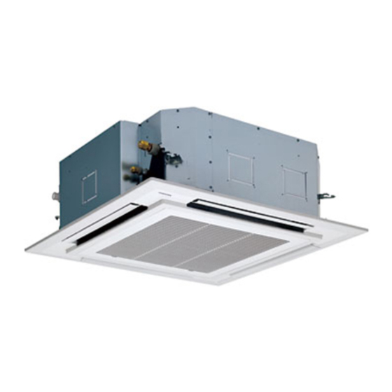
4-way air discharge cassette type
Hide thumbs
Also See for Super MMU-AP0092H:
- Installation manual (40 pages) ,
- Installation manual (27 pages) ,
- Owner's manual (219 pages)
Table of Contents
Advertisement
SERVICE MANUAL
<4-Way Air Discharge Cassette Type>
MMU-AP0092H, MMU-AP0122H,
MMU-AP0152H, MMU-AP0182H,
MMU-AP0242H, MMU-AP0272H,
MMU-AP0302H, MMU-AP0362H,
MMU-AP0482H,
• This Service Manual describes contents of the 4-Way Air Discharge Cassette indoor unit.
For the outdoor unit, refer to the Manual with FILE No. A03-009, A05-004, A05-015.
MMU-AP0562H,
PRINTED IN JAPAN, Oct., 2008 ToMo
FILE NO. A08-004
Advertisement
Table of Contents
Troubleshooting

Subscribe to Our Youtube Channel
Related Manuals for Toshiba Super MMU-AP0092H


Summary of Contents for Toshiba Super MMU-AP0092H
-
Page 1: Service Manual
FILE NO. A08-004 SERVICE MANUAL <4-Way Air Discharge Cassette Type> MMU-AP0092H, MMU-AP0122H, MMU-AP0152H, MMU-AP0182H, MMU-AP0242H, MMU-AP0272H, MMU-AP0302H, MMU-AP0362H, MMU-AP0482H, MMU-AP0562H, • This Service Manual describes contents of the 4-Way Air Discharge Cassette indoor unit. For the outdoor unit, refer to the Manual with FILE No. A03-009, A05-004, A05-015. -
Page 2: Table Of Contents
CONTENTS SAFETY CAUTION ................3 1. SPECIFICATIONS ................ 8 2. CONSTRUCTION VIEWS (EXTERNAL VIEWS) ......12 3. WIRING DIAGRAM ..............16 4. PARTS RATING ................. 17 5. REFRIGERATING CYCLE DIAGRAM ........51 6. CONTROL OUTLINE ..............52 7. CONFIGURATION OF CONTROL CIRCUIT......62 8. -
Page 3: Safety Caution
SAFETY CAUTION The important contents concerned to the safety are described on the product itself and on this Service Manual. Please read this Service Manual after understanding the described items thoroughly in the following contents, and keep them. WARNING Before troubleshooting or repair work, check the earth wire is connected to the earth terminals of the main unit, otherwise an electric shock is caused when a leak occurs. - Page 4 WARNING After repair work, surely assemble the disassembled parts, and connect and lead the removed cables as before. Perform the work so that the cabinet or panel does not catch the inner cables. If incorrect assembly or incorrect cable connection was done, a disaster such as a leak or Assembly/Cabling fire is caused at user’s side.
- Page 5 • New Refrigerant (R410A) This air conditioner adopts a new HFC type refrigerant (R410A) which does not deplete the ozone layer. 1. Safety Caution Concerned to New Refrigerant The pressure of R410A is high 1.6 times of that of the former refrigerant (R22). Accompanied with change of refrigerant, the refrigerating oil has been also changed.
- Page 6 4. Tools (1) Required Tools for R410A Mixing of different types of oil may cause a trouble such as generation of sludge, clogging of capillary, etc. Accordingly, the tools to be used are classified into the following three types. 1) Tools exclusive for R410A (Those which cannot be used for conventional refrigerant (R22)) 2) Tools exclusive for R410A, but can be also used for conventional refrigerant (R22) 3) Tools commonly used for R410A and for conventional refrigerant (R22) The table below shows the tools exclusive for R410A and their interchangeability.
- Page 7 5. Recharge of Refrigerant When recharge of the refrigerant is required, charge the new refrigerant with the specified amount in the procedure as described below. Recover the refrigerant and check there is no refrigerant in the equipment. When the pressure has lowered until indication of the compound gauge pointed -0.1MPa (–76cmHg), open fully the handle Low and turn off the power of vacuum pump.
-
Page 8: Specifications
1. SPECIFICATIONS 1-1. Indoor Unit Model name MMU-AP0092H MMU-AP0122H Cooling capacity (*1) kW Heating capacity (*1) kW 1phase 50Hz 230V(220V-240V) /1phase 60Hz 220V Power supply (Separate power supply for indoor units is required.) Electrical Running current 0.23 / 0.24 0.23 / 0.24... - Page 9 Model name MMU-AP0152H MMU-AP0182H Cooling capacity (*1) kW Heating capacity (*1) kW 1phase 50Hz 230V (220V-240V) / 1phase 60Hz 220V Power supply (Separate power supply for indoor units is required.) Electrical Running current 0.27 / 0.28 0.29 / 0.30 charastaristics Power consumption 0.023 / 0.023 0.026 / 0.026...
- Page 10 Model name MMU-AP0242H MMU-AP0272H MMU-AP0302H Cooling capacity (*1) kW Heating capacity (*1) kW 10.0 1 phase 50Hz 230V (220V-240V) / 1 phase 60Hz 220V Power supply (Separate power supply for indoor units is required.) Electrical Running current 0.38 / 0.39 0.38 / 0.39 0.43 / 0.45 charastaristics...
- Page 11 Model name MMU-AP0362H MMU-AP0482H MMU-AP0562H Cooling capacity (*1) kW 11.2 14.0 16.0 Heating capacity (*1) kW 12.5 16.0 18.0 1 phase 50Hz 230V (220V-240V) / 1 phase 60Hz 220V Power supply (Separate power supply for indoor units is required.) Electrical Running current 0.73 / 0.76 0.88 / 0.92...
-
Page 12: Construction Views (External Views)
2. CONSTRUCTION VIEWS (EXTERNAL VIEWS) MMU-AP0092H, AP0122H 1000 or more 860 to 910 Ceiling open dimension An obstacle 1000 or more The space that is necessary for equipping and service 300 or less Take-in port of wiring Bottom face of ceiling... - Page 13 MMU-AP0152H, AP0182H 1000 or more 860 to 910 Ceiling open dimension An obstacle 1000 or more The space that is necessary for equipping and service 300 or less Take-in port of wiring Bottom face of ceiling Indoor unit Bottom face of ceiling Drain upstanding size Refrigerant pipe connecting port Ø6.4 (Liquid side)
- Page 14 MMU-AP0242H, AP0272H, AP0302H 1000 or more 860 to 910 Ceiling open dimension An obstacle 1000 or more The space that is necessary for equipping and service 300 or less Take-in port of wiring Bottom face of ceiling Indoor unit Bottom face of ceiling Drain upstanding size Refrigerant pipe connecting port Ø9.5 (Liquid side)
- Page 15 MMU-AP0362H, AP0482H, AP0562H 1000 or more 860 to 910 Ceiling open dimension An obstacle 1000 or more The space that is necessary for equipping and service 300 or less Take-in port of wiring Bottom face of ceiling Indoor unit Bottom face of ceiling Refrigerant pipe connecting port Drain pipe Drain upstanding size...
-
Page 16: Wiring Diagram
3. WIRING DIAGRAM 3-1. 4-Way Air Discharge Cassette Type Flow Selector unit (Option) (BLU) (WHI) (RED) (BLK) Control P.C. board (MCC-1431) CN01 CN02 (RED) (GRN) Flow Selector unit Earth screw CN81 CN82 CN334 CN333 CN510 CN504 (BLK) (BLU) (WHI) (WHI) (WHI) (WHI) Motor drive... -
Page 17: Parts Rating
4. PARTS RATING 4-1. Parts Rating MMU- Model AP0092H AP0122H AP0152H AP0182H AP0242H AP0272H AP0302H Fan motor SWF-230-60-2R Motor for horizontal grille MP24ZN3N Pulse motor EDM-MD12TF-3 Pulse motor valve EDM-B25YGTF-3 EDM-B40YGTF-2 TA sensor Lead wire length : 310 mm Vinyl tube TC1 sensor Ø4 size lead wire length : 1200 mm Vinyl tube (Blue) TC2 sensor... -
Page 18: Parts Name Of Remote Controller
4-3. Parts Name of Remote Controller n Display section In the display example, all indicators are displayed for the explanation. Display In reality only, the selected contents are indicated. section • When turning on the main power switch and leak breaker at the first TEMP. - Page 19 9 20 19 Air volume select display Unit Number display The selected air volume mode is displayed. Unit number of the indoor unit selected with the unit select button or abnormal indication (AUTO) (HIGH) of the indoor/outdoor unit. (MED.) (LOW) Central control display Louver Number display Displayed when the air conditioner is used...
-
Page 20: Operation Section
n Operation section Push each button to select a desired operation. • The details of the operation needs to be set up once, afterward, the air conditioner can be used by ON / OFF pushing button only. TEMP. ON / OFF TIMER SET MODE TIME... -
Page 21: Correct Usage
4-4. Correct Usage • When you use the air conditioner for the first time or when you change the SET DATA value, follow the procedure below. From the next time, the operation displayed on the remote controller will start by pushing ON / OFF button only. - Page 22 [In case of cooling] • Start the cooling operation after approx. 1 minute. [In case of heating (For Heat-pump model only)] • The heating operation mode is selected in accordance with the room temperature and operation starts after approximately 3 to 5 minutes. •...
-
Page 23: Adjustment Of Wind Direction
4-6. Adjustment of Wind Direction For best cooling and heating performance, adjust the louvers (adjustment of up/down wind direction) appropriately. CAUTION • If cooling operation is performed with downward air outlet, dew may fall on surface of the cabinet or the horizontal louver resulted in dripping. - Page 24 u 4-way Air Discharge Cassette, 1-way Air Discharge Cassette (2SH series), Under CeilingType TIMER SET MODE TIME SAVE VENT FILTER RESET TEST SWING/FIX UNIT LOUVER Unit select button n How to set up the wind direction n How to stop swinging SWING/FIX SWING/FIX Push...
- Page 25 u 4-way Air Discharge Cassette Type Determine wind direction of the selected (2H series only ) SWING/FIX louver by pushing Unit select • Each time you push the button, the display button changes as follows: TEMP. ON / OFF TIMER SET MODE TIME SAVE...
-
Page 26: Timer Operation
4-7. Timer Operation • A type of timer operation can be selected from the following three types. (Setting of up to 168 hours is enabled.) OFF timer : The operation stops when the time of timer has reached the set time. Repeat OFF timer : Every time, the operation stops after the set time has passed. -
Page 27: Installation Place
4-8. INSTALLATION Installation place CAUTION • Check that the air conditioner is not installed in a place subject to combustible gas leak. Accumulation of combustible gas around the unit may cause a fire. • Drain the dehumidified water from the indoor unit and outdoor unit to a well-drained place. •... - Page 28 4-9. Maintenance WARNING Be sure to turn off the main power switch prior to the maintenance. • Please do not intend to do the daily maintenance and/or Air Filter cleaning by yourself. Cleaning of the air filter and other parts of the air filter involves dangerous work in high places, so be sure to have a service person do it.
- Page 29 NOTE • For environmental conservation, it is strongly recommended that the indoor and outdoor units of the air conditioner in use be cleaned and maintained regularly to ensure efficient operation of the air conditioner. When the air conditioner is operated for a long time, periodic maintenance (once a year) is recommended. Furthermore, regularly check the outdoor unit for rust and scratches, and remove them or apply rustproof treatment, if necessary.
- Page 30 4-10. Air Cinditioner Operations and Performance Check before operation WARNING • Check whether earth wire is disconnected or out of place. • Check that air filter is installed to the indoor unit. Turn on the power switch 12 hours or more before starting before operation.
-
Page 31: When The Following Symptoms Are Found
4-11. When the Following Symptoms Are Found Check the points described below before asking repair servicing. Symptom Cause Outdoor unit • White misty cold air or • Fan of the outdoor unit stops automatically and performs defrost water is out. operation. - Page 32 Confirmation and check When a trouble occurred in the air conditioner, the check code and the indoor unit No. appear on the display part of the remote controller. The check code is only displayed during the operation. If the display disappears, operate the air conditioner according to the following “Confirmation of error history”...
-
Page 33: Precautions For Safety
4-12. Installation Manusl PRECAUTIONS FOR SAFETY • Ensure that all Local, National and International regulations are satisfied. ACCESSORY PARTS • Read this “PRECAUTIONS FOR SAFETY” carefully before Installation. • The precautions described below include the important items regarding safety. Observe them without fail. •... -
Page 34: Selection Of Installation Place
SELECTION OF INSTALLATION PLACE PRECAUTIONS FOR SAFETY CAUTION WARNING New Refrigerant Air Conditioner Installation • Install the air conditioner at enough strong place to withstand the weight of the unit. If the strength is not enough, the unit may fall down resulting in injury. •... - Page 35 SELECTION OF INSTALLATION PLACE n Installation space REQUIREMENT Secure the specified space in the figure for installation and servicing. • When using the air conditioner with 2-way/3-way discharge system, a strong wind blows directly if the u When incorporating flesh-air inlet box Model MMU- A mm ceiling height is lower than the standard.
- Page 36 INSTALLATION n Opening a ceiling and installation of hanging bolts REQUIREMENT • Consider the piping/wiring after the unit is hung Treatment of ceiling Strictly comply with the following rules to prevent damage of the indoor units and human injury. when determining the location of the indoor unit The ceiling differs according to structure of building.
- Page 37 INSTALLATION n Installation of ceiling panel n In case of wireless type Installation of ceiling opening and hanging bolt (Sold separately) The sensor of indoor unit with wireless remote Hanging bolt Level vial (levelness: 5mm or less) controller can receive a signal by distance within Install the ceiling panel according to Installation Hanging bracket Indoor unit...
-
Page 38: Drain Piping Work
DRAIN PIPING WORK n Flexible hose n Connecting drain pipe n Check the draining CAUTION Use the attached flexible hose to adjust center • Connect a hard socket (procured locally) to In the test run, check that water drain is properly discrepancy of the hard vinyl chloride pipe or to the hard socket of the attached supplied performed and water does not leak from the... -
Page 39: Refrigerant Piping And Evacuating
REFRIGERANT PIPING AND EVACUATING DRAIN PIPING WORK n Perform heat insulating n Refrigerant Piping n Permissible Piping Length and • Test water drain while checking the operation sound of the drain pump motor. Height Difference • As shown in the figure, cover the flexible hose 1. -
Page 40: Electrical Work
ELECTRICAL WORK REFRIGERANT PIPING AND EVACUATING n Airtight test/Air purge, etc. n Power supply wire and communication Tightening connection WARNING wires specifications For airtight test, air purge, addition of refrigerant, CAUTION and gas leak check, refer to the Installation 1. Using the specified wires, ensure to connect Power supply wire and communication wires are the wires, and fix wires securely so that the Manual attached to the outdoor unit. - Page 41 ELECTRICAL WORK n Wire connection u Communication line Control wiring between indoor units, and outdoor unit (Up to 1000m) 1.25 mm² REQUIREMENT Wire size (2-core shield wire) (Up to 2000m) 2.0 mm² • Be sure to connect the wires matching the terminal numbers. Incorrect connection causes a trouble. (Up to 1000m) 1.25 mm²...
- Page 42 ELECTRICAL WORK n Remote controller wiring n Wiring for flow selector unit (sold separately) • As the remote controller wire has non-polarity, there is no problem if connections to indoor unit terminal Connect control wiring and power supply following figure when installing a separately sold cooling/ blocks A and B are reversed.
-
Page 43: Applicable Controls
APPLICABLE CONTROLS n Changing of settings of for applicable n When installing separately sold filters Procedure REQUIREMENT controls UNIT LOUVER Each time you push button, indoor unit Be sure to make ceiling setting when installing • When you use this air conditioner for the first numbers in the control group change cyclically. - Page 44 APPLICABLE CONTROLS n When wireless remote controller is used n To secure better effect of eating n How to set up swing type SWING/FIX Change the high-ceiling and filter settings with the DIP switch on the receiver section P .C. board. When it is difficult to obtain satisfactory heating ue 1.
- Page 45 APPLICABLE CONTROLS n How to set up louver lock (No swing) n How to cancel louver lock n Remote controller sensor • About “Dual swing” “Dual” means that louvers are directed UNIT LOUVER 1. Push (right side of the button) for at Set the wind direction to “0000”...
-
Page 46: Test Run
TEST RUN n Before test run In case of wired remote controller In case of wireless remote controller • Before turning on the power supply, carry out Procedure the following procedure. 2, 4 Turn on the power of the air conditioner. 1) Using 500V-megger, check that resistance When power is turned on for the first time after installation, it takes approx. - Page 47 MAINTENANCE Use a vacuum cleaner to remove dust Cleaning of discharge louver 3. Mount the discharge louver. CAUTION from the filters or wash them with water. • First push in one side of the louver, and then The discharge louver can be removed to clean. insert the other side sagging the center Before maintenance, be sure to turn off the •...
-
Page 48: Trouble Shooting
TROUBLE SHOOTING MAINTENANCE n Confirmation and check n Confirmation of error history Maintenance List When a trouble occurred in the air conditioner, When a trouble occurred on the air conditioner, Part Check (visual/auditory) Maintenance the check code and the indoor unit No. appear the trouble history can be confirmed with the on the display part of the remote controller. - Page 49 TROUBLE SHOOTING n Check codes and parts to be checked Check code Wireless remote controller Check method Main Sensor block display AI-NET Outdoor 7-segment display Check code name Judging device remote of receiving unit central control controller On the remote controller (Main remote controller, Central control remote controller) and the interface P .C. board of the display Auxiliary code display...
- Page 50 Batch alarm of general-purpose equipment control General-purpose interface equipment, I/F Differs according to error contents of unit with occurrence of alarm Group control branching unit error TCC-LINK — — (L20 is displayed.) Duplicated central control addresses TCC-LINK : TOSHIBA Carriea Cominication Link.
-
Page 51: Refrigerating Cycle Diagram
5. REFRIGERATING CYCLE DIAGRAM Liquid side Gas side Strainer Capillary tube Air heat exchanger at indoor side Pulse Motor Valve (PMV) Strainer Sensor (TCJ) Sensor (TC2) Sensor (TC1) Sensor Fan motor (TA) Functional part name Functional outline Pulse Motor Valve (Connector CN082 (6P): Blue) 1) Controls super heat in cooling operation 2) Controls under cool in heating operation... -
Page 52: Control Outline
6. CONTROL OUTLINE 6-1. Control Specifications Item Outline of specifications Remarks When power 1) Distinction of outdoor unit supply is reset When the power supply is reset, the outdoors are distinguished and the control is selected according to the distinguished result. 2) Setting of indoor fan speed and existence of air direction adjustment Based on EEPROM data, select setting of the indoor fan... - Page 53 Item Outline of specifications Remarks Room temp. 2) Using the Item code 06, the setup temperature in heating Shift of suction control operation can be corrected. temperature in heating (Continued) operation Setup data Setup temp. correction +0°C +2°C +4°C +6°C Except while sensor of the remote controller is Setting at shipment...
- Page 54 Item Outline of specifications Remarks Air speed 1) Operation with (HH), (H), (L) or [AUTO] mode is carried HH > H+ > H > L+ > L > UL selection out by the command from the remote controller. 2) When the air speed mode [AUTO] is selected, the air speed varies by the difference between Ta and Ts.
- Page 55 Item Outline of specifications Remarks Air speed selection Selection of high ceiling type CODE No. : (Continued): [5d] or selection of high In case of 4-way ceiling on P .C. board SW501 Discharge Cassette type Standard Type 1 Type 3 Type 6 CODE No.
- Page 56 Item Outline of specifications Remarks Freeze prevention 1. In all cooling operation, the air conditioner operates TC1: Temperature of indoor control (Low temp. as de-scribed below based upon temp. detected by heat exchanger sensor release) TC1, TC2 and TCJ sensors. •...
- Page 57 Item Outline of specifications Remarks Recovery control The indoor unit which is under STOP/Thermo-OFF • The indoor unit which is for heating status or which operates in [FAN] mode performs the under thermo-OFF (COOL) refrigerant (Oil) following controls when it received the heating status or which operates in refrigerant (Oil) recovery signal from the outdoor unit.
- Page 58 Item Outline of specifications Remarks Display of < READY> Displayed on the remote controller • < READY> display [READY] 1) When the following check codes are indicated No display for wireless [HEAT READY] type remote controller • Open phase of power supply wiring [P05] was detected. •...
- Page 59 Item Outline of specifications Remarks Louver control: 1) Louver position setup The louver position at In case of 4-way horizontal discharge • When the louver position is changed, the position moves Discharge position at under AP030 necessarily to downward discharge position once to return to Cassette type differs from that at over the set position.
- Page 60 Item Outline of specifications Remarks Louver contro <<Selection of Swing mode>> (Continued): • For the Swing mode, the following three types of modes On the remote controller In case of are selectable and settable by keeping Swing/Direction before the wired remote SWING/FIX 4-way Discharge button pushed for 4 seconds or more on the remote...
- Page 61 Item Outline of specifications Remarks Louver control • If there is the locked louver in the unit, [ ] goes on the For the setting operation, refer to [How to set louver remote controller screen. (Continued): lock] of Installation Manual. In case of 4-way •...
-
Page 62: Configuration Of Control Circuit
7. CONFIGURATION OF CONTROL CIRCUIT 7-1. Indoor Unit 7-1-1. Indoor Controller Block Diagram 1. Connection of wired remote controller Wired remote controller (Up to 2 units) Schedule timer (in weekly timer mode) Weekly timer Display LCD Display Function setup driver Key switch Display LED Function setup... - Page 63 2. Connection of wireless remote controller kit Indoor unit Network adaptor (Option) Wireless remote controller kit Indoor control P.C. board Receiving Network adaptor (MCC-1570) P.C. board P.C. board (MCC-1401) DC20V Remote controller Remote controller Remote controller communication circuit communication circuit communication circuit Emergent Power...
- Page 64 3. Connection of both wired remote controller and wireless remote controller kit Wired remote controller Weekly timer Display LCD Function setup Display driver Key switch EEPROM Function setup DC5V DC5V Power Display LED Key switch circuit Remote controller Secondary Power communication circuit battery circuit...
- Page 65 Remote controller CN41 (Blue), DC20V DC fan output Indoor/Outdoor communication CN333 (White) CN40 (Blue) * Shared with communication of central control system HA (T10) CN61 (Yellow), DC12V Power supply LED Optional power supply Louver of remote controller Remote controller CN309 (Yellow), AC200V CN510 (White), DC12V D403 (Red) communication LED...
- Page 66 7-3. Functions at test run n Cooling/Heating test run check The test run for cooling/heating can be performed from either indoor remote controller or outdoor interface P .C. board. 1. Start/Finish operation of test run ¤ Test run from indoor remote controller Wired remote controller: Refer to the below item of “Test run”...
- Page 67 u In case of wireless remote controller Procedure Operation contents Push [ON/OFF] button on the remote controller. Change the operation mode to [COOL] or [HEAT] using [MODE] button and then select the air speed [ using [FAN]. Test run for cooling operation Test run for heating operation Set [18°C] using [Temperature set] button.
- Page 68 n Check function for operation of indoor unit (Functions at indoor unit side) This function is provided to check the operation of the indoor unit singly without communication with the remote controller or the outdoor unit. This function can be used regardless of operation or stop of the system. However, if using this function for a long time, a trouble of the equipment may be caused.
- Page 69 7-4. Optional Connector Specifications of Indoor P.C. Board Connector Function Specifications Remarks — CN66 — — — Fan output CN32 Shipment setup: ON with indoor unit operation and DC12V OFF with stop are linked. * Single operation by FAN button on remote controller Output is set up from remote controller (DN=31) CN61...
-
Page 70: Applied Control
8. APPLIED CONTROL 8-1. Setup of Selecting Function in Indoor Unit (Be Sure to Execute Setup by a Wired Remote Controller) <Procedure> Execute the setup operation while the unit stops. TEMP. ON / OFF TIMER SET MODE TIME SAVE VENT FILTER RESET TEST... - Page 71 Table: Function selecting item numbers (DN) (Items necessary to perform the applied control at the local site are described.) Item Description At shipment Filter display delay timer 0000 : None 0001 : 150H 0002 : 2500H 0002 : 2500H 0003 : 5000H 0004 : 10000H Dirty state of filter 0000 : Standard...
- Page 72 Item Description At shipment High ceiling selection Type AP009, AP012 AP015, AP018 0000: Standard (Selection of air volume) Discharge 4-way 3-way 2-way 4-way 3-way 2-way Standard 0000 2.7m 2.8m 3.0m 2.8m 3.2m 3.5m (At shipment) 0001 High ceiling — —...
- Page 73 8-2. Applied Control in Indoor Unit n Remote location ON/OFF control box (TCB-IFCB-4E) [Wiring and setup] • Use the exclusive connector for connection with the indoor control P .C. board. • In a group control, the system can operate when connecting with any indoor unit (Control P.C. board) in the group.
- Page 74 n Ventilating fan control from remote controller [Function] • The start/stop operation can be operated from the wired remote controller when air to air heat exchanger or ventilating fan is installed in the system. • The fan can be operated even if the indoor unit is not operating. •...
- Page 75 n Leaving-ON prevention control [Function] • This function controls the indoor units individually. It is connected with cable to the control P .C. board of the indoor unit. • In a group control, it is connected with cable to the indoor unit (Control P .C. board), and the item code 2E is set to the connected indoor unit.
- Page 76 n Address setup (Manual setting from remote controller) In case that addresses of the indoor units will be determined prior to piping work after cabling work (Example of 2-lines cabling) (Real line: Cabling, Broken line: Refrigerant pipe) • Set an indoor unit per a remote controller. Outdoor Outdoor •...
- Page 77 n Confirmation of indoor unit No. position 1. To know the indoor unit addresses though position of the indoor unit is recognized • In case of individual operation (Wired remote controller : indoor unit = 1 : 1) (Follow to the procedure during operation) <Procedure>...
- Page 78 n Function selection setup <Procedure> Perform setting while the air conditioner stops. TEST Push buttons simultaneously for 4 seconds or more. The first displayed unit No. is the master indoor unit address in the group control. In this time, fan and louver of the selected indoor unit operate. ò...
- Page 79 n How to check all the unit No. from an arbitrary wired remote controller <Procedure> Carry out this procedure during stop of system. The indoor unit No. and the position in the identical refrigerant piping can be checked. An outdoor unit is selected, the identical refrigerant piping and the indoor unit No. are displayed one after the other, and then its fan and louver are on.
- Page 80 n How to change all indoor addresses from an arbitrary wired remote controller (It is possible when setting has finished by automatic addresses.) Contents: The indoor unit addresses in each identical refrigerant piping line can be changed from an arbitrary wired remote controller. ¤...
- Page 81 n Function to clear error 1. Clearing method from remote controller ¤ How to clear error of outdoor unit In the unit of refrigerant line connected by indoor unit of the remote controller to be operated, the error of the outdoor unit currently detected is cleared. (Error of the indoor unit is not cleared.) The service monitor function of the remote controller is utilized.
- Page 82 n Monitoring function of remote controller switch When using the remote controller (Model Name: RBC-AMT32E), the following monitoring function can be utilized. Calling of display <Contents> The temperature of each sensor of the remote controller, indoor unit and outdoor unit and the operating status can be checked by calling the service monitor mode from the remote controller.
- Page 83 n LED display on P.C. board 1. D501 (Red) • D501 goes on at the same time when the power supply is turned on. (Goes on with operation of the main microprocessor) • D501 flashes with 1-second interval (every 0.5 second) : When there is no EEPROM or write-in error •...
-
Page 84: Troubleshooting
9. TROUBLESHOOTING 9-1. Troubleshooting Summary 1. Before troubleshooting 1) Applied models S-MMS Multi type models Indoor unit : MMX-APXXX, Outdoor unit : MMY-MAPXXXXT8X, MMY-MAPXXXHT7X ‚ Super Heat Recovery Multi type models Indoor unit : MMX-APXXX, Outdoor unit : MMY-MAPXXXFT8X ƒ... -
Page 85: How To Check
9-2. How to check On the remote controller (Remote controller, Central control remote controller) and on the interface P.C. board of the outdoor unit, LCD display part (Remote controller) or 7-segment display part (on outdoor interface P.C. board) is provided in order to display the operation status. When a trouble occurred, the method to judge the trouble or defective position of the air conditioner by this self-diagnosis function is shown below. - Page 86 (∗) ¡: Goes on, ¥: Flashes, l: Goes off [Remote controller detects error.] A (Alternate) : Flashing condition is alternate when there are two flashing LED. S (Simultaneously) : Two LED flash simultaneously when there are two flashing LED. Check code display Sensor lamp display Outdoor 7-segment Block display (∗)
- Page 87 (∗) ¡: Goes on, ¥: Flashes, l: Goes off Check code display list (Outdoor unit) A (Alternate) : Flashing condition is alternate when there are two flashing LED. S (Simultaneously) : Two LED flash simultaneously when there are two flashing LED. (S-MMS standard &...
- Page 88 (∗) ¡: Goes on, ¥: Flashes, l: Goes off A (Alternate) : Flashing condition is alternate when there are two flashing LED. S (Simultaneously) : Two LED flash simultaneously when there are two flashing LED. Check code display Sensor lamp display Outdoor 7-segment Block display (∗) Main defective position...
- Page 89 (∗) ¡: Goes on, ¥: Flashes, l: Goes off [IPDU in S-MMS standard outdoor unit detects: Representative example] A (Alternate) : Flashing condition is alternate when there are two flashing LED. S (Simultaneously) : Two LED flash simultaneously when there are two flashing LED. Check code display Sensor lamp display Outdoor 7-segment...
- Page 90 9-3. Troubleshooting by Check Display on Remote Controller n In case of wired remote controller (RBC-AMT32E) 1. Confirmation and check When a trouble occurred on the air conditioner, the check code and the indoor unit No. are displayed on the display section of the remote controller.
- Page 91 n In case of central remote controller (TCB-SC642TLE2) ZONE ZONE GROUP CODE 1234 TEST UNIT No. SET DATA SETTING R.C. GROUP SELECT ZONE 1. Confirmation and check When a trouble occurred on the air conditioner, the check code and the indoor unit No. are displayed on the display section of the remote controller.
- Page 92 n Indoor unit display part (Receiving unit) (Wireless type) When specifying the check code, check 7-segment display on the center unit. For the check code which is not displayed on the outdoor 7-segment, confirm it in Section “9-2 How to Check / Check code display list (Indoor unit)”. : Goes off, : Goes on, : Flash (0.5 second)
- Page 93 Lamp indication Check code Cause of trouble occurrence Operation Timer Ready Heat exchanger sensor (TCJ) error Heat exchanger sensor (TC2) error Temp. sensor error in indoor unit Heat exchanger sensor (TC1) error Alternate flash Room temp.
- Page 94 n Others (Except check code) Lamp indication Check code Cause of trouble occurrence Operation Timer Ready — During test run Simultaneous flash Operation Timer Ready COOL/HEAT disagreement — (Automatic cooling/heating setup to automatic cooling/heating unavailable model, heating setup to cooling only model) Alternate flash...
- Page 95 9-4. Check Code and Check Position Displayed on the Remote Controller and Outdoor Unit (7-Segment Display of Interface) <In case of SUPER MODULAR MULTI SYSTEM> Check code Detected Main Outdoor 7-segment display Check code name Status Error detection condition Check item (position) position remote controller...
- Page 96 Check code Detected Main Outdoor 7-segment display Check code name Status Error detection condition Check item (position) position remote Check code Auxiliary code controller — No corresponding indoor All stop Indoor unit is not found when indoor automatic • Check the communication line connection between unit during automatic address start was set up.
- Page 97 Check code Detected Main Outdoor 7-segment display Check code name Status Error detection condition Check item (position) position remote Check code Auxiliary code controller 01: IPDU1 error IPDU communication error All stop Communication of each IPDU • Check connection of communication connector and 02: IPDU2 error (P .C.
- Page 98 Check code Detected Main Outdoor 7-segment display Check code name Status Error detection condition Check item (position) position remote Check code Auxiliary code controller — Outdoor temp sensor All stop During operation of compressor in HEAT • Check installation of TE1 sensor and TL sensor. miscabling (TE1, TL) mode, the TE1 detection temp was higher •...
- Page 99 Check code Detected Main Outdoor 7-segment display Check code name Status Error detection condition Check item (position) position remote Check code Auxiliary code controller — Compressor 1 case All stop Compressor 1 case thermostat performed • Check compressor 1 case thermo circuit. (Connector, cable, P .C. board) thermo operation protective operation.
- Page 100 Check code Detected Main Outdoor 7-segment display Check code name Status Error detection condition Check item (position) position remote Check code Auxiliary code controller — Compressor 2 case All stop Compressor 2 case thermostat • Check compressor 2 case thermo circuit. (Connector, cable, P .C. board) thermo operation operated.
- Page 101 Check code Detected Main Outdoor 7-segment display Check code name Status Error detection condition Check item (position) position remote controller Check code Auxiliary code — — Duplicated indoor units with priority All stop Indoor units with priority were • Check display of indoor unit with priority. (Displayed on indoor unit with priority) duplicated.
- Page 102 Check code Detected Main Outdoor 7-segment display Check code name Status Error detection condition Check item (position) position remote Check code Auxiliary code controller — — Indoor Indoor fan motor error Corresponding • Check the lock of fan motor (AC fan). unit only stops.
- Page 103 Check code Detected Main Outdoor 7-segment display Check code name Status Error detection condition Check item (position) position remote controller Check code Auxiliary code — Outdoor liquid back All stop <In cooling> • Check full close operation of outdoor PMV (1, 2). detection error While the system operated in cooling mode, high •...
- Page 104 Check code Detected Main Outdoor 7-segment display Check code name Status Error detection condition Check item (position) position remote Check code Auxiliary code controller 08: Out of step IPDU Outdoor fan IPDU error All stop (Auxiliary code: 08) • Fan motor check 0A: IDC operation Fan IPDU position detection circuit •...
- Page 105 Error detected by TCC-LINK central control device Check code Display on Outdoor 7-segment display Detected position Check code name Status Error detection condition Check item (position) central control Check code Auxiliary code device — TCC-LINK TCC-LINK central control Operation Signal is not transmit from central •...
-
Page 106: Sensor Characteristics
9-5. Sensor Characteristics Indoor Unit n Temperature sensor characteristics Characteristic-1 Indoor TA sensor Temperature [˚C] Indoor TC1, TC2, TCJ sensors Characteristic-2 90 100 Temperature [˚C]... -
Page 107: Detachments
10. DETACHMENTS Part name Procedure Remarks Suction grille XCAUTIONX Suction grille Knobs of the suction grille hook Be sure to put on the gloves and long-sleeved shirt at disassembling work; otherwise an injury will be caused by a part, etc. 1. - Page 108 Part name Procedure Remarks Electric parts cover (Continued) 1. Detachment Adjust corner cap Adjust corner cap 1) Pull knob of the adjust corner cap to the arrow direction, remove strap of the adjust corner cap from pin of the panel and then remove all the 4 corners of the cap.
- Page 109 Part name Procedure Remarks 1. Detachment Ceiling panel Clamp 1) Carry out works of item 1 of 2 and item 1 of 3 . 2) Remove the flap connector Louv Louver motor wir Louver motor wiring er motor wiring (CN510, White, 20P) connected to the control P .C.
- Page 110 Part name Procedure Remarks 1. Detachment Control P.C. board Clamp 1) Carry out work of item 1 of 2 . 2) Remove connectors which are connected from the control P.C. board to the other parts and then remove wiring from the clamp. CN510 : Louver motor (20P , White) CN34 : Float switch (3P , Red) CN504 : Drain pump (2P , White)
- Page 111 Part name Procedure Remarks 1. Detachment Drain cap Drain cap (outside) 1) Carry out work of item 1 of 1 . 2) Loosen screws (3 positions) fixing the drain cap (outside) and then turn the drain cap to the arrow mark direction to remove it. CLOSE CLOSE NOTE :...
- Page 112 Part name Procedure Remarks 1. Detachment Fan motor Fixing screw A 1) Carry out work of item 1 of 2 . 2) Remove connectors which are connected from the control P.C. board to the other parts and then remove each wiring from the clamp. CN510 : Louver motor (20P , White) CN34 : Float switch (3P , Red) CN504 : Drain pump (2P , White)
- Page 113 Fixing screws (Ø4 × 8) When exchanging the fan motors of the Clamp models MMU-AP0092H to AP0320H, take off lead wire from the clamp filter, which is connected to CN334 of the fan motor to be exchanged and then connect the removed lead wire to a new fan motor.
- Page 114 Part name Procedure Remarks 1. Detachment Drain pump Fixing screw A 1) Carry out works of item 1 of 2 and item 1 of 6 . 2) Remove the drain pump connector (CN504, Drain por Drain port ain port White, 2P) connected to the control P .C. board and then remove the lead wire from the clamp.
- Page 115 Part name Procedure Remarks 1. Detachment Float switch assembly 1) Carry out works of item 1 of 7 and works from 1) to 5). Float s Float switch assemb Float switch assembly witch assembly 2) Remove the fixing screw and then remove the float switch assembly.
- Page 116 Part name Procedure Remarks 1. Detachment PMV motor PMV body PMV motor 1) Carry out work of item 1 of 10 . 2) Remove the relay connector of PMV motor. 3) Peel the butyl rubber adhered to the main unit of the pulse motor valve (PMV) until PMV can be seen and then loosen the nuts fixing PMV motor with double spanner to remove PMV motor.
- Page 117 Part name Procedure Remarks 1. Detachment Heat exchanger 1) Recover the refrigerant gas. 2) Carry out work of item 1 of 10 . 3) Remove refrigerant pipe at indoor unit side. 4) Remove the fixing screws and then remove the piping cover. (Ø4 ×10, 3 pcs.) 5) Remove the drain hose from the drain pump and remove the fixing screws to remove the drain pump stand.
-
Page 118: Board Exchange Procedures
11. P.C. BOARD EXCHANGE PROCEDURES 11-1. Exchange of P.C. Board for Indoor Service Part code Models P.C. board 431-6V-379 MMU-AP 2H series MCC-1570 CAUTION <Model Name: MMU-AP 2H> For the above models, set the CODE No. to “ ” and the setting data 0000 (initial) to “0001” <Note: when replacing the P.C. - Page 119 [1] Setting data read out from EEPROM The setting data modified on the site, other than factory-set value, stored in the EEPROM shall be read out. TEST Step 1 Push buttons on the remote controller simultaneously for more than 4 seconds. ∗...
- Page 120 [3] Wiring the setting data to EEPROM <Fig. 1 RBC-AMT32E> The settings stored in the EEPROM of the P .C. board for indoor unit servicing are the factory-set values. TEST Step 1 Push buttons on the remote controller CODE simultaneously for more than 4 seconds. SET DATA SETTING UNIT...
- Page 121 Step 6 Check the setting data displayed at this time with the setting data down in [1] (on page 122). 1. If the setting data is different, modify the setting data by pushing buttons for the timer setting to the data put down in [1]. The operation completes if the setting data is displayed. 2.
- Page 122 <Make a note of the setup contents. (Item code list (Example))> Item Setting data Factory-set value Filter sign lighting time Depending on Type Filter pollution leve 0000: standard Central control address 0099: Not determined 0002: +2°C Heating suction temperature shift (flooring installation type: 0) Existence of automatic 0001: No auto mode...
-
Page 123: Exploded Views And Parts List
12. EXPLODED VIEWS AND PARTS LIST MMU-AP0092H, AP0122H, AP0152H, AP0182H, AP0242H 236 258 234, 248 230, 231, 232, 233, 252, 253 210, 211 227, 228, 229, 251, 254, 255 206, 207 224, 225 228, 251, 254 227, 229, 255... - Page 124 Model Name MMU-AP Location Parts No. Description 0092H 0122H 0152H 0182H 0242H 43120248 Fan Ass’y, Turbo 43166011 Remote Controller 43166012 Remote Controller 43122110 Bell Mouth 43172206 Pan Ass’y, Drain 43172207 Pan Ass’y, Drain 4314J405 Refrigeration Cycle Ass’y 4314J406 Refrigeration Cycle Ass’y 4314J407 Refrigeration Cycle Ass’y 43146707...
- Page 125 MMU-AP0092H, AP0122H, AP0152H, AP0182H, AP0242H Model Name MMU-AP Location Parts No. Description 0092H 0122H 0152H 0182H 0242H 43050425 Sensor Ass’y, Service, TC (F6) 43050426 Sensor, Service, TA 43150320 Sensor Ass’y, Service, TG (F4) 43160574 Terminal, 4P 43160575 Terminal Block, 2P , 20A 4316V379 P .C.
- Page 126 MMU-AP0272H, AP0302H, AP0362H, AP0482H, AP0562H 214, 216 231, 233, 253 228, 251, 254 206, 208 224,225 234, 248...
- Page 127 Model Name MMU-AP Location Parts No. Description 0272H 0302H 0362H 0482H 0562H 43120247 Fan Ass’y, Turbo 43120248 Fan Ass’y, Turbo 43166011 Remote Controller, SX-A4EE 43166012 Remote Controller, SX-A5EE 43122110 Bell Mouth 43172206 Pan Ass’y, Drain 43172208 Pan Ass’y, Drain 4314J407 Refrigeration Cycle Ass’y 4314J408 Refrigeration Cycle Ass’y...
- Page 128 MMU-AP0272H, AP0302H, AP0362H, AP0482H, AP0562H Model Name MMU-AP Location Parts No. Description 0272H 0302H 0362H 0482H 0562H 43050425 Sensor Ass’y, Service, TC (F6) 43050426 Sensor, Service, TA 43150320 Sensor Ass’y, Service, TG (F4) 43160574 Terminal, 4P 43160575 Terminal Block, 2P , 20A 4316V379 P .C.
- Page 129 RBC-U31PG (W, WS)-E, RBC-U31PGS (W, WS)-E 308, 309 306, 307, 323, 324 310, 311 Model Name RBC-U31 Location Parts No. Description U31PG(W)-E U31PG(WS)-E U31PGS(W)-E U31PGS(WS)-E 43409207 Grille, Air Inlet 43480017 Air Filter, ABS + PPNET 4302D003 Motor, Louver, MP24Z3N 43407145 Outlet, Air Form, PS-F 43407146 Outlet, Air Form, PS-F...
- Page 130 RBC-AX31U (W)-E, RBC-AX31U (WS)-E 356, 357 Model Name Location Parts No. Description RBC-AX31U (W)-E RBC-AX31U (WS)-E 43459011 P .C. Board Ass’y, Remote Receiver 43462010 Cover, WRS, ABS 43461006 Sheet, PC 43108018 Cover, Panel, WRS 43108019 Cover, Panel, WRS 43460126 Lead...
- Page 131 TOSHIBA CARRIER CORPORATION 23-17, TAKANAWA 3 CHOME, MINATOKU, TOKYO, 108-8580, JAPAN Copyright © 1999 to 2008 TOSHIBA CARRIER CORPORATION, ALL Rights Reserved.
Need help?
Do you have a question about the Super MMU-AP0092H and is the answer not in the manual?
Questions and answers