Table of Contents
Advertisement
Quick Links
Download this manual
See also:
User Manual
Advertisement
Table of Contents

Related Manuals for Extron electronics FOX T UWP 302


Summary of Contents for Extron electronics FOX T UWP 302
- Page 1 User Guide Fiber Optic Extender FOX T UWP 302 Two Input Fiber Optic Transmitter 68-2092-01 Rev. A 07 13...
- Page 2 Safety Instructions • English Chinese Simplified (简体中文) 警告: 产品上的这个标志意在警告用户该产品机壳内有暴露的危险 WARNING: This symbol, , when used on the product, is intended to alert the user of the presence of uninsulated dangerous voltage within 电压, 有触电危险。 the product’s enclosure that may present a risk of electric shock. 注...
- Page 3 FCC Class A Notice This equipment has been tested and found to comply with the limits for a Class A digital device, pursuant to part 15 of the FCC rules. The Class A limits provide reasonable protection against harmful interference when the equipment is operated in a commercial environment.
- Page 4 Conventions Used in this Guide Notifications The following notifications are used in this guide: A warning indicates a situation that has the potential to result in death or WARNING: severe injury. CAUTION: A caution indicates a situation that may result in minor injury. ATTENTION: Attention indicates a situation that may damage or destroy the product or associated equipment.
-
Page 5: Table Of Contents
........... 1 ....13 About This Guide ..........1 Simple Instruction Set Control ......13 About the FOX T UWP 302 ......... 1 SIS Programming Guide ....... 13 System Compatibility ........1 Command and Response Tables for SIS Commands ..........16 Cable Transmission Modes ...... - Page 6 FOX T UWP 302 Wallplate Transmitter • Contents...
-
Page 7: Introduction
HD component video; stereo audio; and RS-232 signals over fiber optic cabling. It has dedicated connectors for RGB, HDMI, and audio. To configure and control the FOX T UWP 302, connect a host device, such as a computer, and enter Simple Instruction Set (SIS) commands (see... -
Page 8: Key Features
DVI Plus receivers up to 1920x1200, including HDTV 1080p/60. Compatible with FOX series DVI and VGA receivers up to 1600x1200, including HDTV 1080p/60. NOTE: The FOX T UWP 302 is not compatible with the FOX 3G HD-SDI, FOX 3G DVC, or FOX AV models. -
Page 9: Application Diagram
Application Diagram The following diagram shows a typical application of the FOX T UWP 302 with two input sources, connected to a fiber optic receiver. Extron XPA 1002 Power Ampli er Extron SI 28 W IR Surface- L/ M mount... -
Page 10: Installation And Operation
Mounting and Making Connections • Operation Installation Overview Install the FOX T UWP 302 into an electrical UL Listed junction box. CAUTION: Risk of personal injury. Failure to check the items listed below may result in personal injury. ATTENTION: Failure to check the items listed below may result in property damage. -
Page 11: Rear Panel Features
Right Side Rear Figure 2. FOX T UWP 302 Rear Connectors from the Side and Rear Panels Fiber connector — For one-way video, audio, and serial communication from the transmitter to a receiver, connect a fiber optic cable between the Tx port on the transmitter and the Rx port on a receiver. -
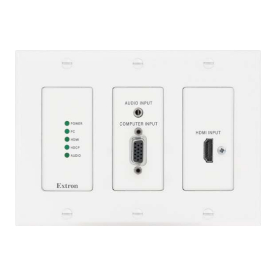
Page 12: Front Panel Features
Computer Input connector — Connect a video source to the female 15-pin HD connector. HDMI Input connector — Connect a source device to the HDMI connector. This connector can accept HDMI, DVI, or dual mode DisplayPort video signals. FOX T UWP 302 Wallplate Transmitter • Installation and Operation... -
Page 13: Under-The-Faceplate Features
12). Config port — Connect a host device, such as a PC, to the mini-USB type B config port for RS-232 protocol control of all FOX T UWP 302 functions. Configure the Simple Instruction Set Control FOX T UWP 302 with SIS commands (see... -
Page 14: Mounting And Making Connections
Disconnect power from all devices at the source. Connect all cables to the FOX T UWP 302 rear panel connectors. Secure the FOX T UWP 302 enclosure to the box using three of the provided screws into the slots at the top and bottom of the device. -
Page 15: Connecting The Hdmi Connector
However, for only one fiber optic cable, the HDMI signal output by OPTICAL the receiver is not HDCP-compliant. • To receive responses from the controlled device and for HDCP compliance, install both fiber optic cables and leave link 2 enabled. FOX T UWP 302 Wallplate Transmitter • Installation and Operation... -
Page 16: Wiring For Remote Rs-232 And Alarm Communication
NOTE: If power is lost or if link 2 optical light is disconnected, lost, or broken, alarm pins 1 and 2 internally short. FOX T UWP 302 Wallplate Transmitter • Installation and Operation... -
Page 17: Wiring The Power Supply
The length of the exposed (stripped) copper wires is important. The ideal length is 3/16 inch (5 mm). TIP: Do not tin the stripped power supply leads. Tinned wires are not as secure in the captive screw connectors and could be pulled out. FOX T UWP 302 Wallplate Transmitter • Installation and Operation... -
Page 18: Operation
Operation After all devices are connected and powered, the system is fully operational. The FOX T UWP 302 can be configured through SIS commands (see Simple Instruction Set Control on page 13) or the FOX Extenders control program (see FOX Extenders Control Program on page 21). -
Page 19: Sis Configuration And Control
To enable serial control of the transmitter, use a computer running the HyperTerminal or Extron DataViewer utility, or a control system to enable serial control of the transmitter. Connect the computer to the FOX T UWP 302 through the front panel Config port or the Installation and Operation rear panel Remote RS-232 connector (see on page 4). -
Page 20: Error Responses
Error responses When the FOX T UWP 302 receives an SIS command and determines it is valid, it performs the command and sends the corresponding response to the host device. If the command is determined invalid or contains invalid parameters, the transmitter returns an error response to the host. - Page 21 VGA user 576p 1080i assigned or 2-ch audio 2-ch audio imported 1 HDMI user 720p 1080p assigned or 2-ch audio 2-ch audio imported 2 720p 2-ch audio (default - digital) FOX T UWP 302 Wallplate Transmitter • SIS Configuration and Control...
-
Page 22: Command And Response Tables For Sis Commands
Video input select X1! • Select input View video input X1!] View currently selected source. NOTE: The FOX T UWP 302 saves the last input selection when cycling power. Auto switch mode Disable auto switch mode Manual input switching only. 0AUSW Ausw0... - Page 23 = default) = Total pixels of the default value (depends on the input rate) ±255 = Horizontal start = default) = EDID output resolution See the tables on page 15. FOX T UWP 302 Wallplate Transmitter • SIS Configuration and Control...
-
Page 24: Advanced Configuration
= no source detected = source detected with HDCP = source detected but no HDCP is present = Input video format = auto detect (default) = RGB (full range) = YUV FOX T UWP 302 Wallplate Transmitter • SIS Configuration and Control... - Page 25 = source detected with HDCP = source detected but no HDCP is present = Unit name Text string up to 24 characters ( X1& = Extron device name FOX-T-UWP-302 FOX T UWP 302 Wallplate Transmitter • SIS Configuration and Control...
- Page 26 = Vendor or manufacturer name = Transmit (Tx) output power in dBm = Receive (Rx) optical power in dBm = Operation temperature of the SFP modules in degrees Celsius FOX T UWP 302 Wallplate Transmitter • SIS Configuration and Control...
-
Page 27: Fox Extenders Control Program
The Extron FOX Extenders Control Program provides an alternate method to control and configure the FOX T UWP 302. The application provides controls to adjust device parameters that are specific to the basic and advanced setup of the transmitter. Users can also manage firmware and check for updates to the application. -
Page 28: Starting The Software
Help menu. • From the Windows Start Menu, select from the FOX Extenders FOX Extenders Help Control Program folder. The main screen opens (see figure 12 on page 23). FOX T UWP 302 Wallplate Transmitter • FOX Extenders Control Program... -
Page 29: Top Menu
The File menu contains options for connecting and disconnecting the device and exiting the FOX Extenders Control Program. Figure 13. File Menu Options that appear gray are not available. FOX T UWP 302 Wallplate Transmitter • FOX Extenders Control Program... - Page 30 To exit the program, select from the menu. Exit File Tools Menu The Tools menu contains options for displaying device information or configuring the device. Figure 14. Tools Menu FOX T UWP 302 Wallplate Transmitter • FOX Extenders Control Program...
- Page 31 Depending on the chosen reset option, different settings are cleared. Figure 16. Reset Unit Menu NOTE: Be careful to select the intended reset option. Selecting the incorrect reset can result in unintended loss of settings. FOX T UWP 302 Wallplate Transmitter • FOX Extenders Control Program...
-
Page 32: Update Firmware
Audio Gain/Atten. Reset Figure 18. Audio Gain and Attenuation Reset Dialog Box Presets Reset — Is not available for the FOX T UWP 302. Update Firmware The Update Firmware option opens the Extron Firmware Loader application. This application is used to upload new firmware to the connected device. - Page 33 . The Trace Window dialog box opens. Tools Trace Window To clear existing information, click the button. Clear Click the button to close the Trace Window dialog box. Close FOX T UWP 302 Wallplate Transmitter • FOX Extenders Control Program...
- Page 34 The Check for Updates option verifies that the latest version of the FOX Extenders Control Program is being used. If there is a new version available, the option to install it becomes available. From the menu, select Help Check for Updates FOX T UWP 302 Wallplate Transmitter • FOX Extenders Control Program...
- Page 35 Application description • Figure 21. About FOX Extenders Control Program Dialog Box Click the button to close this dialog box and return to the main screen of the application. FOX T UWP 302 Wallplate Transmitter • FOX Extenders Control Program...
-
Page 36: Main Screen
(connecting the Tx port of an HDMI receiver to the Rx port of an HDMI transmitter). NOTE: For transmission of HDMI video with HDCP content, two fibers are required. FOX T UWP 302 Wallplate Transmitter • FOX Extenders Control Program... -
Page 37: Control Tab
Auto Switch Mode — Allows the device to auto switch inputs based on the chosen configuration. The options are Disabled, Priority to Highest Active, or Priority to Lowest Active. NOTE: The default setting on the FOX T UWP 302 is Priority to Highest Active Control tab The Control tab contains picture and audio adjustments. - Page 38 The field to the right of a slider shows the current value for the associated setting. NOTE: The Total Pixels setting depends on the input rate. It is ±255 of the default value. FOX T UWP 302 Wallplate Transmitter • FOX Extenders Control Program...
- Page 39 In the Audio Gain/Atten. panel, click and drag the slider to the desired level. The current value is displayed in a field below the slider control. Audio Output Level — Is not available for the FOX T UWP 302. I/O Configuration Tab The I/O Configuration tab contains options for input and output settings.
- Page 40 For each input, select the desired audio input type from the drop-down list. Input Figure 28. Audio Input 1 Options NOTE: Default setting: Audio Input Selection is for all inputs. Auto Advanced Tab Figure 29. Advanced Tab FOX T UWP 302 Wallplate Transmitter • FOX Extenders Control Program...
- Page 41 Advanced Configuration panel NOTE: This setting is not available for the FOX T UWP 302. EDID Configuration Tab EDID is a data structure used to communicate video display information, including native resolution and vertical refresh rate requirements, to a source device. The source device then outputs the optimal video format for the display based on the provided EDID data, ensuring proper video image quality.
- Page 42 Import EDID panel EDID files can be imported to the FOX T UWP 302 and saved in a table on the device. NOTE: When an EDID file is imported to a user assigned input location, the EDID is automatically assigned to the selected user input.
- Page 43 Export EDID panel EDID files on the FOX T UWP 302 can be exported to the connected PC. To open and view them, use the Extron EDID Manager software, available at www.extron.com. The EDID Manager software aids in troubleshooting any EDID related issues that may occur during configuration or operation of an AV system.
-
Page 44: Reference Information
Firmware Updates Firmware Loader To upload and update firmware for the FOX T UWP 302, download the new firmware to a connected computer and upload the firmware with the Firmware Loader utility or the FOX Extenders Control Program (see to the FOX Extenders Control Program Help File). -
Page 45: Installing Firmware Loader
Follow the instructions on the Installation Wizard screens to install the new firmware on the computer. A Release Notes file, giving information on what has changed in the new firmware version, and a set of instructions for updating the firmware are also loaded. FOX T UWP 302 Wallplate Transmitter • Reference Information... -
Page 46: Installing Firmware With Firmware Loader
Close Firmware Loader when the field shows , the Remaining Time 00.00.00 column shows , and the field shows Progress 100% Status completed NOTE: See Simple Instruction Set Control on page 13 for reset information. FOX T UWP 302 Wallplate Transmitter • Reference Information... - Page 47 Extron Warranty Extron Electronics warrants this product against defects in materials and workmanship for a period of three years from the date of purchase. In the event of malfunction during the warranty period attributable directly to faulty workmanship and/or materials, Extron Electronics will, at its option, repair or replace said products or components, to whatever extent it shall deem necessary to restore said product to proper operating condition, provided that it is returned within the warranty period, with proof of purchase and description of malfunction to: USA, Canada, South America,...
Need help?
Do you have a question about the FOX T UWP 302 and is the answer not in the manual?
Questions and answers