
Related Manuals for Extron electronics DTP T USW 223


Summary of Contents for Extron electronics DTP T USW 223
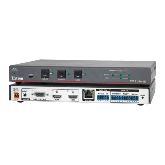
- Page 1 User Guide HDMI Extenders DTP T USW 223 Three Input Switcher with Integrated DTP Transmitter 68-2490-01 Rev. A 11 13...
-
Page 2: Safety Instructions
Safety Instructions Safety Instructions • English Инструкция по технике безопасности • Русский WARNING: This symbol, , when used on the product, is intended to ПРЕДУПРЕЖДЕНИЕ: Данный символ, , если указан alert the user of the presence of uninsulated dangerous voltage within the на... - Page 3 Conventions Used in this Guide Notifications The following notifications are used in this guide: CAUTION: A caution indicates a situation that may result in minor injury. ATTENTION: Attention indicates a situation that may damage or destroy the product or associated equipment. NOTE: A note draws attention to important information.
- Page 4 Extron Safety and Regulatory Compliance accessibility, and related topics, see the “ Guide ” on the Extron website. Copyright © 2013 Extron Electronics. All rights reserved. Trademarks All trademarks mentioned in this guide are the properties of their respective owners. ® (SM)
-
Page 5: Table Of Contents
Contents Introduction Remote Control ............1 ........... 12 About this Guide ..........1 Contact Closure Control ........12 About the DTP T USW 233 Switcher ....1 Simple Instruction Set Control ......13 TP Cable ............2 Host-to-Switcher Communications ....13 Control Communications ........ -
Page 6: Introduction
Introduction • About this Guide About the DTP T USW 233 Switcher • • Features About this Guide This guide describes the Extron DTP T USW 233 switching transmitter. The switcher outputs a signal to a compatible DTP receiver. This guide describes how to install, operate, and configure the switcher. -
Page 7: Tp Cable
TP Cable Extron recommends XTP DTP 24 shielded twisted pair (STP) cable for best performance. Category (CAT) 5e, CAT 6, CAT 6a, or CAT 7 STP or unshielded twisted pair (UTP) cable is acceptable. Extron recommends at least 24 AWG, solid conductor, STP cable with a minimum bandwidth of 400 MHz. -
Page 8: Installation And Operation
Installation and Operation This section describes the installation and the operation of the DTP T USW 233, including: Mounting the Unit • • Connections and Reset Button Operation • Mounting the Unit Mounting instructions can be found in Mounting the Switcher on page 18. - Page 9 Audio input port — If desired, plug an analog audio input into the switching AUDIO transmitter via this stereo mini jack connector. Analog audio is not embedded into the digital video signal. NOTES: • The analog audio input on this connector is Tip (+) in addition to the digital audio that may be Ring (-)
-
Page 10: Connector And Cable Details
Remote Tally port — If desired, to remotely identify the currently selected TALLY input, plug a locally-constructed device into this 3.5 mm, 4-pole captive screw connector. Connect the power wire for the device into the +V pin and connect the ground wire for the each indicator into the corresponding tally out pin, 1, 2, or 3. -
Page 11: Cable Recommendations
Supported cables The DTP T USW 233 is compatible with CAT 5e, 6, 6a, and 7 shielded twisted pair (F/UTP, SF/UTP, and S/FTP) and unshielded twisted pair (U/UTP) cable. Cable recommendations Extron recommends using the following practices to achieve full transmission distances up to 230 feet (70 m) and reduce transmission errors. -
Page 12: Power Supply Wiring
Power supply wiring NOTES: • The power supply included with the switching transmitter can normally power both units. • If you have removed the ground jumpers (see Disconnecting the Ground page 19) because of ground potential differences, one unit of the pair cannot remotely power the other unit. -
Page 13: Front Panel Configuration Port
IR and RS-232 connector wiring Figure 6 shows how to wire the Remote RS-232 and Over DTP RS-232 and IR connectors. IR Device RS-232 Device Figure 6. IR and RS-232 Connectors Wiring NOTES: • The IR Tx and Rx line pair and the RS-232 Tx and Rx line pairs must each cross once between their connectors and the source or destination. -
Page 14: Operation
Operation Controls and Indications STATUS AUTO SIGNAL SWITCH CONFIG HDCP AUTO MODE NORMAL DTP T USW 233 Figure 8. Power Indicators Auto Switch mode indicator Auto Switch LED — When lit, indicates that the switcher is in auto-input switching mode. When unlit, the switch is in normal (manual) mode (see Selecting the switch mode on page 11). -
Page 15: Front Panel Operations
Status LEDs Status LEDs — Signal LEDs (1 through 3) —Indicates that the switcher detects Horizontal sync (Signal LED 1) or TMDS clock (Signal LED 2 and Signal LED 3) on the associated input. HDCP LEDs (2 and 3) —Indicates that the input signal is HDCP encrypted. Front Panel Operations The following paragraphs detail the power up process and provide sample procedures for switching inputs, changing between normal and auto-input switching mode, and toggling... -
Page 16: Reset
Selecting the switch mode NOTE: In the auto-input switching mode that is available from the front panel, the switcher selects to the highest numbered input with a sync signal present. See the Front panel mode SIS commands on page 15 for an auto-input switching low mode, which selects the lowest numbered input. -
Page 17: Remote Control
Remote Control This section includes: Contact Closure Control • • Simple Instruction Set Control The DTP T USW 233 switcher can be remotely controlled via its rear panel Remote RS-232 port, its front panel configuration (USB) port, and its rear panel Remote Contact port. Remote control devices can be: •... -
Page 18: Simple Instruction Set Control
The switcher-initiated messages are listed below: © Copyright 20yy Extron Electronics DTP T USW 233 nnnn The switcher issues the copyright message when it first powers on. is the firmware version number and is the part number. -
Page 19: Using The Command And Response Table
Using the Command and Response Table command and response table begins on the next page. Symbols are used throughout the table to represent variables in the command and response fields. Command and response examples are shown throughout the table. The ASCII to HEX conversion table below is for use with the command and response table. - Page 20 Command and Response Table for SIS Commands SIS Command Response Additional description Command Function (Host to Unit) (Unit to Host) Select and view input Select an input Select input to transmit to the •All connected receiver. Example: Select input 1. In01•All View input selection Input...
- Page 21 SIS Command Response Additional description Command Function (Host to Unit) (Unit to Host) EDID Minder NOTE: See table 1, below for the EDID values. X& X&] Assign EDID to an input Defaults: 03 and 50. EDID EdidA Save the EDID of the connected Save EDID of display connected to the EDID EdidS...
- Page 22 SIS Command Response Additional description Command Function (Host to Unit) (Unit to Host) Input 1 (only) video format X1!] Set format Set input 1 to format Example: 1*0\ Set input 1 to autodetect. Typ0 X1!] View format View set format. X1!] View detected format View detected format (...
-
Page 23: Reference Information
Reference Information This section provides procedures for mounting the DTP T USW 233 switching transmitter and disconnecting the ground between it and a compatible receiver. • Mounting the Switcher • Disconnecting the Ground Mounting the Switcher ATTENTION: • Installation and service must be performed by authorized personnel only. •... -
Page 24: Ul Rack-Mounting Guidelines
UL Rack-Mounting Guidelines The following Underwriters Laboratories (UL) requirements pertain to the installation of the unit into a rack. • Elevated operating ambient temperature — If installed in a closed or multi-unit rack assembly, the operating ambient temperature of the rack environment may be greater than room ambient. - Page 25 Locate and lift off jumpers JMP1 and JMP2 (see figure 12). JMP2 JMP1 Figure 12. Jumper Locations Reinstall the switcher cover, securing it in place with the screws removed in step 2. Reinstall the switcher in the rack or other installation option (see Mounting the Switcher on page 18).
- Page 26 Extron Electronics makes no further warranties either expressed or implied with respect to the product and its quality, performance, merchantability, or fitness for any particular use. In no event will Extron Electronics be liable for direct, indirect, or consequential damages resulting from any defect in this product even if Extron Electronics has been advised of such damage.
Need help?
Do you have a question about the DTP T USW 223 and is the answer not in the manual?
Questions and answers