Advertisement
NOTE:
Please read all instructions
carefully before using this
product
Safety Notice
Hardware Identifier
Assembly Instruction
Parts List
Resistance Chart
Warranty
Ordering Parts
Model
MWM 1800
Retain This
Manual for
Reference
08-28-01
OWNER'S
MANUAL
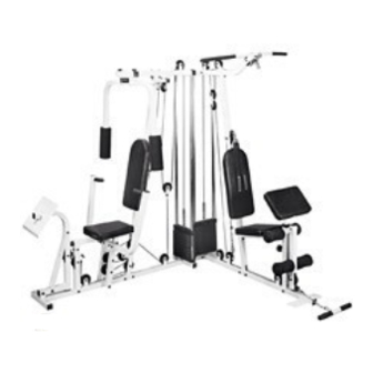
MARCY HOME GYM
IMPEX FITNESS PRODUCTS
14777 DON JULIAN RD., CITY OF INDUSTRY, CA 91746
Tel: (800) 999-8899 Fax: (626) 961-9966
www.impex-fitness.com
info@impex-fitness.com
MWM 1800
Advertisement
Table of Contents

Related Manuals for Impex MWM 1800


Summary of Contents for Impex MWM 1800
- Page 1 NOTE: Please read all instructions carefully before using this product Safety Notice MARCY HOME GYM Hardware Identifier MWM 1800 Assembly Instruction Parts List Resistance Chart Warranty Ordering Parts Model MWM 1800 Retain This Manual for Reference IMPEX FITNESS PRODUCTS 08-28-01 14777 DON JULIAN RD., CITY OF INDUSTRY, CA 91746...
-
Page 2: Table Of Contents
ORDERING PARTS..................………… 24 BEFORE YOU BEGIN Thank you for selecting the MARCY MWM 1800 HOME GYM by IMPEX FITNESS PRODUCTS. For your safety and benefit, read this manual carefully before using the machine. As a manufacturer, we are committed to provide you complete customer satisfaction. -
Page 3: Important Safety Notices
IMPORTANT SAFETY NOTICE PRECAUTIONS This exercise machine is built for optimum safety. However, certain precautions apply whenever you operate a piece of exercise equipment. Be sure to read the entire manual before you assemble or operate your machine. In particular, note the following safety precautions: 1. -
Page 5: Assembly Instructions
ASSEMBLY INSTRUCTION Tools Required Assembling the Machine: Two Adjustable Wrenches and Allen Wrenches. NOTE: It is strongly recommended this machine to be assembled by two or more people to avoid possible injury. STEP 1 (See Diagram 1) A.) Attach the Left Base Frame (#15) to the Right Base Frame (#3). Secure them with one Bracket (#55), two M10 x 2 ¾”... - Page 6 STEP 2 (See Diagram 2) A.) Attach Right Vertical Beam (#6) to the Right Base Frame (#3). Secure it with two M10 x 2 ¾” Carriage Bolts (#70), ¾” Washers (#50), and M10 Aircraft Nuts (#81). B.) Attach the Right Seat Support (#2) to the Right Base Frame (#3). Secure it with one M10 x 2 ¾”...
- Page 7 STEP 3 (See Diagram 3) A.) Align four 1” Rubber Bumpers (#63) to the holes on the Right Base Frame (#3). Insert the four Guide Rods (#16) through the Rubber Bumpers into the holes on the Right Base Frame (#3). Slide two Selector Stems (#27) onto the Guide Rods. Insert a Selector Rod (#24) through the hole on each Selector Stem (#27).
- Page 8 STEP 4 (See Diagram 4) A.) Attach the Left Vertical Beam (#17) to the Left Base Frame (#15). Secure it with two M10 x 2 ¾” Carriage Bolts (#70), ¾” Washers (#50), and M10 Aircraft Nuts (#81). B.) Attach the Left Upper Frame (#18) to the Left Vertical Beam (#17), and the Right Upper Frame (#7).
- Page 9 STEP 5 (See Diagram 5) A.) Attach the Front Press Base (#4) to the Right Base Frame (#3). Secure it with a M10 x 9 ¼” Axle (#85), two ¾” Washers (#50), and two M10 Aircraft Nuts (#81). B.) Attach the two Front Presses (#5) to the Front Press Base (#4). Secure each Front Press with two M10 x 2 ¾”...
- Page 10 STEP 6 (See Diagram 6) A.) Insert the axle on the Left Butterfly (#8) through the hole on the Right Upper Frame (#7) from the bottom up. Slide a 1 ½” Washer (#52) and 1 3/8” Lock Ring (#92) onto the Axle. Align the holes and secure the Ring with a M6 x 1 5/8” Hex Bolt (#77) and M6 Aircraft Nut (#80).
- Page 11 Cable Loop Diagram...
- Page 12 STEP 7 (See Diagram 7 & Cable Loop Diagram) A.) Attach the two Swivel Pulley Brackets (#11) to the Right Upper Frame (#7). Secure each Bracket with one M12 x 4 3/8” Allen Bolt (#72), two 1” Washers (#51) and one M12 Aircraft Nut (#82).
- Page 13 STEP 8 (See Diagram 8 & Cable Loop Diagram) A.) Attach a Chain (#65) to the Right Vertical Beam (#6). Secure the Chain with one M10 x 1” Allen Bolt (#67), two 3/4” Washers (#50), and one M10 Aircraft Nut (#81). Attach one end of the 136”...
- Page 14 STEP 9 (See Diagram 9 & Cable Loop Diagram) A.) Attach one end of the140” Leg Press Cable (#36) to the opening hole on the Right Seat Support (#2), underneath the rubber bumper. Secure it with one M10 x 2 ½” Allen Bolt (#69), two ¾”...
- Page 15 DIAGRAM 9...
- Page 16 STEP 10 (See Diagram 10 & Cable Loop Diagram) A.) Attach the 114” Upper Cable (#32) to the front opening on the Left Upper Frame (#18). NOTE: The Ball Stopper on the Cable needs to be underneath the Frame. B.) Attach a Pulley (#60) to the opening. Secure it with one M10 x 2 ½” Allen Bolt (#69), two 7/8”...
- Page 17 STEP 11 (See Diagram 11) A.) Attach the 39” Ab Cable (#35) to the opening on the Left Vertical Beam (#17). Attach a Pulley to the opening. Secure the Pulley with one M10 x 2 ½” Allen Bolt (#69), two 7/8 x ½”...
- Page 18 DIAGRAM 11...
- Page 19 STEP 12 (See Diagram 12) A.) Now move the machine to its final position. After installing the weight stack, it will be too heavy to move. B.) Install 9 Weight Plates (#26) to each set of Guide Rods. To install the plate, lift up the Selector Rod in the center, hold the plate at an angle and place between the two Guide Rods (#16) then drop it down.
- Page 20 STEP 13 (See Diagram 13) A.) Insert one Foam Roll Tube (#19) halfway through the hole on the Left Seat Support (#14). Insert one Foam Roll Tube (#19) halfway through the hole on the Leg Developer (#13). Push four Foam Rolls (#42) onto the Tubes from both sides. Plug the Foam Roll End Caps (#41) to each end of the Foam Rolls.
- Page 21 STEP 14 (See Diagram 14) A.) Attach a Backrest Board (#30) to the Right Vertical Beam (#6). Secure it with two M8 x 2 1/8” Allen Bolts (#76) and 5/8” Washers (#49). B.) Attach the Seat Pad (#29) to the Right Seat Support (#2). Secure it with two M8 x 2 1/8” Allen Bolts (#76) and 5/8”...
-
Page 22: How To Use
HOW TO USE How to use the quick release connector. The Clip is removed from the Connector. Connector Clip Place the chain in between the connector and insert the Clip through the holes. Chain Insert Push down the Clip to secure. -
Page 23: Parts List
PARTS LIST KEY NO. DESCRIPTION Q’ty 1” Washer Leg Press Frame 1 ½” Washer Right Seat Support 1” x 7/8” Bushing Right Base Frame 1” x 3/8” Bushing Front Press Base Bracket Front Press 1 ½” End Cap (Impex Logo) Right Vertical Beam 1 ¾”... -
Page 24: Resistance Chart
MWM 1800 Weight Resistance Chart Weight Plate Station Low Pulley Lat Pull Ab Strap Butterfly Leg Press Front Press *Each plate weights 10 lb. *Resistance measured in pounds. *Numbers are approximate. Actual number may vary. -
Page 25: Warranty
IMPEX INC. LIMITED WARRANTY IMPEX Inc. ("IMPEX") warrants this product to be free from defects in workmanship and material, under normal use and service conditions, for a period of two years on the Frame from the date of purchase. This warranty extends only to the original purchaser. IMPEX's obligation under this Warranty is limited to replacing or repairing, at IMPEX's option.
Need help?
Do you have a question about the MWM 1800 and is the answer not in the manual?
Questions and answers