Table of Contents
Advertisement
NOTE:
Please read all instructions
carefully before using this
product
Table of Contents
Safety Notice
Resistance Chart
Model
MWM-977
Retain This
Manual for
Reference
100716
OWNER'S
MANUAL
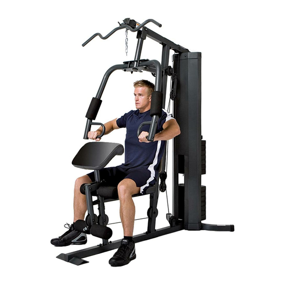
MARCY CLASSIC
MWM 977 HOME GYM
IMPEX
2801 S. Towne Ave., Pomona, CA 91766
Tel: (800) 999-8899 Fax: (626) 961-9966
www.impex-fitness.com
info@impex-fitness.com
®
®
INC.
Advertisement
Table of Contents

Subscribe to Our Youtube Channel
Related Manuals for Impex MARCY CLASSIC MWM-977


Summary of Contents for Impex MARCY CLASSIC MWM-977
- Page 1 ® Safety Notice MARCY CLASSIC Hardware Pack MWM 977 HOME GYM Assembly Instruction Parts List Resistance Chart Warranty Ordering Parts Model MWM-977 Retain This Manual for Reference 100716 ® OWNER'S IMPEX INC. 2801 S. Towne Ave., Pomona, CA 91766 MANUAL Tel: (800) 999-8899 Fax: (626) 961-9966 www.impex-fitness.com...
-
Page 2: Table Of Contents
RESISTANCE CHART…………...............………..25 WARRANTY....................…………..26 ORDERING PARTS..................………… 26 BEFORE YOU BEGIN Thank you for selecting the MARCY CLASSIC MWM-977 HOME GYM by ® IMPEX INC. For your safety and benefit, read this manual carefully before using the machine. As a manufacturer, we are committed to provide you complete customer satisfaction. -
Page 3: Important Safety Notices
IMPORTANT SAFETY NOTICE PRECAUTIONS This exercise machine is built for optimum safety. However, certain precautions apply whenever you operate a piece of exercise equipment. Be sure to read the entire manual before you assemble or operate your machine. In particular, note the following safety precautions: 1. -
Page 4: Warning Label Placement
WARNING LABEL PLACEMENT The warning labels shown here have been placed on the Rear Stabilizer and Upper Frame. If the labels are missing or illegible, please call customer service at 1-800-888-8899 for replacements. Apply the labels in the location shown. -
Page 5: Hardware Pack
HARDWARE PACK NOTE: The following parts are not drawn to scale. Please use your own ruler to measure the size. - Page 6 HARDWARE PACK NOTE: The following parts are not drawn to scale. Please use your own ruler to measure the size.
-
Page 7: Assembly Instructions
ASSEMBLY INSTRUCTION Tools Required for Assembling the Machine: Two Adjustable Wrenches and Allen Wrenches. NOTE: It is strongly recommended this machine to be assembled by two or more people to avoid possible injury. STEP 1 (See Diagram 1) A.) Insert the two Guide Rods (#17) into the holes on the Rear Stabilizer (#4). Secure each Guide Rod with one M10 x ¾”... - Page 8 DIAGRAM 1 STEP 2 (See Diagram 2)
- Page 9 A.) Attach the Leg Developer Holder (#5) onto the Base Frame (#3). Secure it with two M10 x 2 ¾” Carriage Bolts (#55), one 1 ¾” x 4 ¾” Bracket (#20), two ¾” Washers (#65), and two M10 Aircraft Nuts (#69). B.) Attach the Seat Support (#6) to the Vertical Frame (#2).
- Page 10 STEP 3 (See Diagram 3)
- Page 11 A.) Attach the Weight Stack Cover (#16) to the bracket on Rear Stabilizer (#4) and Upper Frame (#1). B.) Attach two Weight Stack Cover Brackets (#29) to top and bottom of Weight Stack Cover. C.) Secure the Weight Stack cover Bracket, Weight Stack Cover to Upper Frame with four M6 x ¾”...
- Page 12 A.) Attach the Front Press Base (#8) to the Upper Frame (#1). Secure it with one 3” Front Press Axle (#38), two Ø ¾” Spacers (#68), and two M10 Aircraft Nuts (#69). Do not over tighten the Nuts. B.) Attach the Right Butterfly (#9) to the open bracket on Front Press Base. Secure it with one 2 5/8” Butterfly Axle (#39), two Ø...
- Page 13 DIAGRAM 4...
- Page 14 STEP 5 (See Diagram 5) A.) Attach the Backrest Board (#24) to the Vertical Frame (#2). Secure it with two M8 x 2 ¾” Allen Bolts (#61) and two Ø 5/8” Washers (#66). B.) Attach the Seat Pad (#25) to the Seat Support (#6). Secure it with four M8 x 5/8” Allen Bolts (#62) and two Ø...
- Page 15 STEP 6 (See Diagram 6) A.) Attach one Swivel Pulley Bracket (#14) to the open bracket on the back of Vertical Frame (#2). Secure it with one M10 x 2 ½” Allen Bolt (#57), two Ø ¾” Washers (#65), and one M10 Aircraft Nut (#69). Do not over tighten the Nut and Bolt. Make sure the Swivel Pulley Bracket can swivel freely.
- Page 16 DIAGRAM 6...
- Page 17 CALBE LOOP...
- Page 18 STEP 7 (See Diagram 7 & Cable Loop Diagram) A.) Attach the 116” Upper Cable (#48) to the front opening on the Upper Frame. NOTE: The Ball Stopper on the Cable needs to be underneath the Frame. B.) Attach a Pulley (#42) to the opening. Secure it with one M10 x 2 ¾” Allen Bolt (#56), two Ø...
- Page 19 DIAGRAM 7...
- Page 20 STEP 8 (See Diagram 8 & Cable Loop Diagram) A.) Attach one end of the 91” Butterfly Cable (#49) to one Butterfly Cable Bracket (#12). Secure it with one M10 x ¾” Allen Bolt (#60) and one M10 Aircraft Nut (#65). B.) Draw the Cable towards the right open Swivel Pulley Bracket (#14).
- Page 21 STEP 9 (See Diagram 9 & Cable Loop Diagram) A.) Attach the 134” Lower Cable (#50) to the opening on the bottom of the Leg Developer (#7). B.) Attach a Pulley (#42) to the opening. Secure it with one M10 x 2 ¾” Allen Bolt (#56), two ...
- Page 22 DIAGRAM 9...
- Page 23 STEP 10 (See Diagram 10) A.) Attach Lat Bar (#18) to the Upper Cable (#48) with two C-Clips (#34) and one Chain (#33) when doing Lat Pull exercises. B.) Attach Lat Bar to the Lower Cable (#50) with two C-Clips (#34) and one Chain (#33) when doing Arm Curl exercises C.) Remove Arm Curl Stand.
- Page 24 Combination Lock Set Up Instruction The Lock is set at the manufacturer to the open at 0-0-0 (all zeros are positioned in the middle). It is recommended to change the combination to ensure safety. Please follow the below steps to change the combination: 1.
-
Page 25: Parts List
PARTS LIST KEY NO. DESCRIPTION Q’ty Upper Frame Ø 1” Cone-shaped End Cap Vertical Frame 2” Square End Cap Base Frame Ø 2” End Cap Rear Stabilizer Ø 1” End Cap Leg Developer Holder M10 x 2 ¾” Carriage Bolt Seat Support M10 x 2 ¾”... -
Page 26: Resistance Chart
MWM977 WEIGHT RESISTANCE CHART Weight Plate Front Press Butterfly Lat Pull Low Pulley Note: Each plate weights 10 lbs. Numbers are approximate. Actual weights may vary. Values for Butterfly are for each arm. -
Page 27: Warranty
® IMPEX INC. LIMITED WARRANTY ® IMPEX Inc. ("IMPEX ") warrants this product to be free from defects in workmanship and material, under normal use and service conditions, for a period of two years on the Frame from the date of purchase. This warranty extends only to the original purchaser.
Need help?
Do you have a question about the MARCY CLASSIC MWM-977 and is the answer not in the manual?
Questions and answers