Advertisement
NOTE:
Please read all instructions
carefully before using this
product
Safety Notice
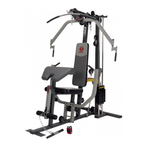
MARCY HOME GYM
Hardware Identifier
MWM 1600
Assembly Instruction
Parts List
Resistance Chart
Warranty
Ordering Parts
Model
MWM1600
Retain This
Manual for
Reference
07-17-03
IMPEX FITNESS PRODUCTS
14777 DON JULIAN RD., CITY OF INDUSTRY, CA 91746
OWNER'S
Tel: (800) 999-8899 Fax: (626) 961-9966
MANUAL
www.impex-fitness.com
info@impex-fitness.com
Advertisement
Table of Contents

Related Manuals for Impex MWM 1600


Summary of Contents for Impex MWM 1600
- Page 1 NOTE: Please read all instructions carefully before using this product Safety Notice MARCY HOME GYM Hardware Identifier MWM 1600 Assembly Instruction Parts List Resistance Chart Warranty Ordering Parts Model MWM1600 Retain This Manual for Reference 07-17-03 IMPEX FITNESS PRODUCTS 14777 DON JULIAN RD., CITY OF INDUSTRY, CA 91746...
-
Page 2: Table Of Contents
ORDERING PARTS..................BEFORE YOU BEGIN Thank you for selecting the MARCY MWM 1600 HOME GYM by IMPEX FITNESS PRODUCTS. For your safety and benefit, read this manual carefully before using the machine. As a manufacturer, we are committed to provide you complete customer satisfaction. -
Page 3: Important Safety Notices
IMPORTANT SAFETY NOTICE PRECAUTIONS This exercise machine is built for optimum safety. However, certain precautions apply whenever you operate a piece of exercise equipment. Be sure to read the entire manual before you assemble or operate your machine. In particular, note the following safety precautions: 1. -
Page 5: Assembly Instructions
ASSEMBLY INSTRUCTION Tools Required to Assemble the Machine: Two Adjustable Wrenches and Allen Wrenches NOTE: It is strongly recommended this machine be assembled by two or more people to avoid possible injury. STEP 1 (See Diagram 1) A.) Attach the Rear Stabilizer (#2) to the back of the Base Frame (#1). Then attach the Rear Vertical Beam (#4) to the back of the Rear Stabilizer (#2). - Page 6 STEP 2 (See Diagram 2) A.) Attach the Front Press Base (#7) to the Base Frame (#1). Align the holes and insert through a M10 x 9 5/8” Axle (#38). Secure the Axle with two ¾” Washers (#114) and M10 Aircraft Nuts (#112).
- Page 7 STEP 3 (See Diagram 3) A.) Attach the Seat Support (#12) to the Leg Developer Holder (#118). Secure it with three M10 x 5/8” Allen Bolts (#102) and ¾” Washers (#114). B.) Attach the Leg Developer Holder (#118) to the Base Frame (#1). Secure it with a M10 x 3 ¾” Carriage Bolt (#92), ¾”...
- Page 8 STEP 4 (See Diagram 4) A.) Slide two Rubber Bumpers (#70) onto the two Weight Plate Guide Rods (#19). Insert the two Rods into the holes on the Base Frame (#1). B.) Slide ten Weight Plates (#27) from the top of the Guide Rods (#19) down to the Bumper. Insert the Selector Rod (#16) into the center hole on the Plates.
- Page 10 STEP 5 (See Diagram 5) A.) Attach the Right Butterfly (#9) to the Upper Frame (#10). Slide a 1 ½” Washer (#51) and 1 3/8” Steel Cap (#84) onto the axle. Secure the Cap with a M6 x 1 ½” Hex Bolt (#106) and M6 Aircraft Nut (#113).
-
Page 11: Cable Loop Diagram
CABLE LOOP DIAGRAM... - Page 12 STEP 6 (See Diagram 6 & Cable Loop Diagram) A.) Insert the 110” Upper Cable (#30) through the opening at the front of the Upper Frame (#10). NOTE: The Ball Stopper on the Cable should be underneath the Frame. Attach a Big Pulley (#79) to the opening and secure it with one M10 x 3 ½”...
- Page 13 STEP 7 (See Diagram 7 & Cable Loop Diagram) A.) Attach a Pulley (#79) to the bracket on the Right Butterfly (#9). Secure it with a M10 x 1 ¾” (#99), two ¾” Washers (#114), and one M10 Aircraft Nut (#112). B.) Repeat the step (A) above to install another Pulley to the Left Butterfly.
- Page 14 STEP 8 (See Diagram 8 & Cable Loop Diagram) A.) Insert the 159” Lower Cable (#31) through the opening on the bottom of the Leg Developer (#13). NOTE: The Ball Stopper on the Cable should be in front of the Leg Developer. Attach a Pulley (#79) to the opening and secure it with one M10 x 2 ½”...
- Page 15 STEP 9 (See Diagram 9 & Cable Loop Diagram) A.) Attach the136” Bench Press Cable (#34) to the open slot on Pulley Cable Hanger (#45) previously installed in Step 8. B.) Pull the Cable downward to the open bracket on top of the Base Frame (#1). Install a Pulley (#79).
- Page 16 STEP 10 (See Diagram 10 & Cable Loop Diagram) A.) Plug one 1/2” Plastic Bushing (#76) into the hole on the side of the Rear Vertical Beam (#4) from the bottom up. Insert the “long bolt end” of the 72 ½” Power Booster Cable (#33) into the hole.
- Page 17 STEP 11 (See Diagram 11) A.) Attach the Seat (#28) to the Seat Support (#12). Secure it with two M8 x 2 ½” Allen Bolts (#103) and 5/8” Washers (#115). B.) Attach the Backrest Pad (#29) to the Front vertical Beam (#3). Secure it with two M8 x 2” Allen Bolts (#104) and 5/8”...
-
Page 19: How To Use
HOW TO USE How to use the quick release connector. The Clip is removed from the Connector. Connector Clip Place the chain in between the connector and insert the Clip through the holes. Chain Insert Push down the Clip to secure. -
Page 20: Parts List
Parts List KEY NO. DESCRIPTION Q’ty 2” Square End Cap 1 3/8” Bumper 2” Impex Logo End Cap Base Frame 1 ¾” Impex Logo End Cap Rear Stabilizer 1 ½” Impex Logo End Cap Front Vertical Beam 1 ½” Cone-shaped End Cap Rear Vertical Beam 1”... -
Page 22: Warranty
IMPEX INC. LIMITED WARRANTY IMPEX Inc. ("IMPEX") warrants this product to be free from defects in workmanship and material, under normal use and service conditions, for a period of two years on the Frame from the date of purchase. This warranty extends only to the original purchaser. IMPEX's obligation under this Warranty is limited to replacing or repairing, at IMPEX's option.
Need help?
Do you have a question about the MWM 1600 and is the answer not in the manual?
Questions and answers