Table of Contents
Advertisement
NOTE:
Please read all instructions
carefully before using this
product
Table of Contents
Safety Notice
Hardware Identifier
Assembly Instruction
Parts List
Resistance Chart
Warranty
Ordering Parts
Model
MWM-1509
Retain This
Manual for
Reference
111102
OWNER'S
MANUAL
MARCY
14777 DON JULIAN RD., CITY OF INDUSTRY, CA 91746
Tel: (800) 999-8899 Fax: (626) 961-9966
www.impex-fitness.com
info@impex-fitness.com
®
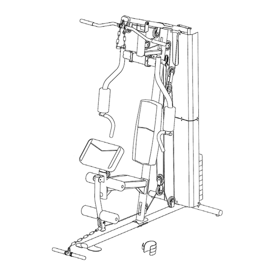
HOME GYM
MWM-1509
®
IMPEX
INC.
Advertisement
Table of Contents

Subscribe to Our Youtube Channel
Related Manuals for Impex MARCY MWM-1509


Summary of Contents for Impex MARCY MWM-1509
-
Page 1: Home Gym
NOTE: Please read all instructions carefully before using this product ® MARCY HOME GYM Table of Contents Safety Notice MWM-1509 Hardware Identifier Assembly Instruction Parts List Resistance Chart Warranty Ordering Parts Model MWM-1509 Retain This Manual for Reference 111102 OWNER'S MANUAL ®... -
Page 2: Table Of Contents
ORDERING PARTS..................………… 21 BEFORE YOU BEGIN ® Thank you for selecting the MARCY MWM-1509 HOME GYM by IMPEX INC. For your safety and benefit, read this manual carefully before using the machine. As a manufacturer, we are committed to provide you complete customer satisfaction. -
Page 3: Important Safety Notices
IMPORTANT SAFETY NOTICE PRECAUTIONS This exercise machine is built for optimum safety. However, certain precautions apply whenever you operate a piece of exercise equipment. Be sure to read the entire manual and all posted warning labels before you assemble or operate your machine. In particular, note the following safety precautions: 1. -
Page 4: Warning Label Replacement
WARNING LABEL REPLACEMENT The warning labels shown here have been placed on the Rear Base and Upper Frame. If the labels are missing or illegible, please call customer service at 1-800-888-8899 for replacements. Apply the labels in the location shown. -
Page 5: Hardware Pack
HARDWARE PACK NOTE: The following parts are not drawn to scale. Please use your own ruler to measure the size. - Page 6 HARDWARE PACK NOTE: The following parts are not drawn to scale. Please use your own ruler to measure the size.
- Page 7 HARDWARE PACK NOTE: The following parts are not drawn to scale. Please use your own ruler to measure the size.
-
Page 8: Assembly Instructions
ASSEMBLY INSTRUCTION Tools Required Assembling the Machine: Two Adjustable Wrenches, two Allen Wrenches, and one Philips Screwdriver. NOTE: It is strongly recommended this machine be assembled by two or more people to avoid possible injury. STEP 1 (See Diagram 1) A.) Connect two Lower Guide Rods (#46) and two Upper Guide Rods (#45) with two M10 Stud Bolts (#48). - Page 9 DIAGRAM 1...
- Page 10 STEP 2 (See Diagram 2) A.) Slide 9 Weight Plates (#66) onto the Guide Rods. Make sure the grooves on the Weight Plates are all facing the back of the machine and downward. Insert the Selector Rod (#47) through the center hole on the Weight Plates. B.) Slide the Selector Stem (#65) onto the Guide Rods.
- Page 11 DIAGRAM 2...
- Page 12 STEP 3 (See Diagram 3) A.) Attach the Left Butterfly (#10) to the open bracket on the Front Press Base (#9). Secure it with one M12 x 4” Hex Bolt (#84), two Ø 1” Washers (#88), and one M12 Aircraft Nut (#91). B.) Slide a Butterfly Foam Roll (#57) onto the Left Butterfly arm.
- Page 13 CABLE LOOP DIAGRAM...
- Page 14 STEP 4 (See Diagram 4 & Cable Loop Diagram) A.) Attach the 122” Upper Cable (#40) to the open bracket underneath the front of Upper Frame (#8). B.) Attach a Pulley (#49) to the open bracket. Secure it with one M10 x 1 ¾” Allen Bolt (#75), two Ø...
- Page 15 DIAGRAM 4...
- Page 16 STEP 5 (See Diagram 5 & Cable Loop Diagram) A.) Attach one end of the 119” Butterfly Cable (#41) to the hook on the Right Butterfly (#11). B.) Draw the Cable to the right open bracket on the back of Upper Vertical Frame (#15). C.) Attach a Pulley to the bracket.
- Page 17 STEP 6 (See Diagram 6 & Cable Loop Diagram) A.) Attach the 130” Lower Cable (#39) to the opening on the bottom of the Leg Developer (#7). B.) Attach a Pulley (#49) to the opening. Secure it with one M10 x 2 ½” Allen Bolt (#77), two Pulley Bushings (#33), and one M10 Aircraft Nut (#90).
- Page 18 DIAGRAM 6...
-
Page 19: Exploded Diagram
EXPLDOED DIAGRAM... -
Page 20: Parts List
PARTS LIST KEY NO. DESCRIPTION Q’ty Main Base Frame Handle Grip Rear Base Frame Ø 1” Con-shaped End Cap Front Base Frame Foam Roll End Cap Lower Vertical Frame Ø 2” End Cap Seat Support Ø 1 ¾” End Cap 5 ½”... -
Page 21: Resistance Chart
WM-1509 WEIGHT RESISTANCE CHART WEIGHT PLATE Station Front Press Butterfly Lat Pull Low Pulley Leg Developer * Each plate weights approximately 10 lbs. *Numbers are approximate. Actual weight may vary. *Value for butterfly is for each arm. -
Page 22: Warranty
® IMPEX INC. LIMITED WARRANTY ® IMPEX Inc. ("IMPEX ") warrants this product to be free from defects in workmanship and material, under normal use and service conditions, for a period of two years on the Frame from the date of purchase. This warranty extends only to the original purchaser.
Need help?
Do you have a question about the MARCY MWM-1509 and is the answer not in the manual?
Questions and answers