Table of Contents
Advertisement
PM266A PRO/ PM266A
Copyright
All rights are reserved. No part of this publication may be reproduced, transmitted, transcribed,
stored in a retrieval system or translated into any language or computer language, in any form or by
any means, electronic, mechanical, magnetic, optical, chemical, manual or otherwise, without the
prior written permission of the company. Brands and product names are trademarks or registered
trademarks of their respective companies.
The vendor makes no representations or warranties with respect to the contents herein and especially
disclaim any implied warranties of merchantability or fitness for any purpose. Further the vendor
reserves the right to revise this publication and to make changes to the contents herein without
obligation to notify any party beforehand. Duplication of this publication, in part or in whole, is not
allowed without first obtaining the vendor's approval in writing.
Disclaimer
We make no warranty of any kind with regard to the content of this user's manual. The content is
subject to change without notice and we will not be responsible for any mistakes found in this user's
manual. All the brand and product names are trademarks of their respective companies.
FCC Compliance Statement
This equipment has been tested and found to comply with the limits of a Class B digital device,
pursuant to Part 15 of the FCC Rules. These limits are designed to provide reasonable protection
against harmful interference in a residential installation. This equipment generates, uses and can
radiate radio frequency energy and, if not installed and used in accordance with the instructions, may
cause harmful interference to radio communications. Operation of this equipment in a residential area
is likely to cause harmful interference in which case the user will be required to correct the
interference at his own expense. However, there is no guarantee that interference will not occur in a
particular installation.
120410043M2N
Advertisement
Table of Contents

Related Manuals for Albatron PM266A PRO


Summary of Contents for Albatron PM266A PRO
- Page 1 PM266A PRO/ PM266A Copyright All rights are reserved. No part of this publication may be reproduced, transmitted, transcribed, stored in a retrieval system or translated into any language or computer language, in any form or by any means, electronic, mechanical, magnetic, optical, chemical, manual or otherwise, without the prior written permission of the company.
-
Page 2: Package Contents
Package Contents: PM266A PRO/ PM266A mainboard IDE ATA Cable FDC Cable USB Bracket (optional) Installation and Setup Driver CD PM266A PRO/ PM266A User Manual Dimensions (Micro - ATX form factor): 225mm x 244mm (WxL) Operating System ® Windows 98/ ME/ XP/ 2000... -
Page 3: Table Of Contents
......................2 PECIFICATION ................... 5 UICK ONTENT ABLE ....................... 6 ONFIGURATION Layout of PM266A PRO ..................6 Layout of PM266A....................7 ..................8 ARDWARE NSTALLATION CPU Processor Installation ................... 8 Memory Installation ..................... 9 Back Panel Configuration................... 11 Front Panel Indicator: SW/LED、PWRLED ............. 13 Connectors ...................... -
Page 4: Chapter 1. Getting Started
The PM266A PRO/ PM266A also support six USB 2.0 ports. The PM266A PRO/ PM266A also include an infrared header. The PM266A PRO also comes with a LAN Chip (VIA VT6103) and provides a back panel LAN port capable of 10/ 100 Mbit/s transmission speeds. -
Page 5: Specification
Southbridge Chipset – VIA VT8235 I/O Controller – Winbond W83697HF AC’97 Codec – VIA VT1616 LAN Controller – VIA VT6103 (Only for PM266A PRO) DRAM Memory: Supports DDR266 (PC2100)/ DDR200 (PC1600) SDRAM Supports 64 MB/ 128 MB/ 256 MB/ 512 MB/ 1 GB unbuffered & non-ECC DIMM... -
Page 6: Flash Memory
PM266A PRO/ PM266A BUS Slots: AGP slot (AGP2.0, 4X/2X) x 1 PCI bus slot x 3 Flash Memory: Supports flash memory functionality Supports ESCD functionality Hardware Monitor Function: Monitors CPUFAN/ CHASFAN Speeds Monitors System Voltage Infrared: Supports IrDA Version 1.0 SIR Protocol with a maximum baud rate of up to 115.2 Kbps Supports SHARP ASK-IR Protocol with maximum baud rate of up to 57600 bps AC’97 Sound Codec Onboard:... -
Page 7: Watch Dog Timer
PM266A PRO/ PM266A VIA VT6103 LAN Controller on board: 1/10/100 MHz full and half duplex operation Independent 2K byte FIFOs for receive and transmit Magic packet and wake-on-address filtering Software controllable power down I/O facilities: One multi-mode Parallel Port capable of supporting the following specifications: 1. -
Page 8: Quick Content Table
PM266A PRO/ PM266A Quick Content Table Function Content Location Page CPU Socket 478 DDR DIMM Slots DDR DIMM 1、2 ATX Power Connector ATX_ PWR、ATX_12V IDE Connectors IDE1/2 FDC Connector AGP Slot PCI 1、2、3 PCI Slots CPU FAN、Chassis FAN、 CPUFAN、CHASFAN、AUXFAN Auxiliary FAN SW/LED、PWRLED... -
Page 9: Configuration
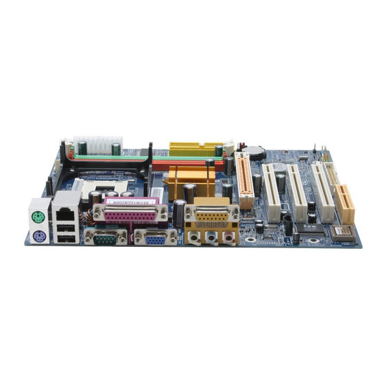
PM266A PRO/ PM266A Configuration Layout of PM266A PRO KB/MS CPUFAN USB/LAN Socket 478 PRT/COM/VGA IDE2 IDE1 ATX_12V ATX_PWR P4M266A AUXFAN SOUND VT6103 COM2 BAT1 Winbond W83697HF CASE OPEN PCI1 VT8235 PCI2 BIOS Codec PCI3 PWRLED CHASFAN FRONT AUDIO IrDA USB1... -
Page 10: Layout Of Pm266A
PM266A PRO/ PM266A Layout of PM266A KB/MS CPUFAN Socket 478 PRT/COM/VGA IDE2 IDE1 ATX_12V ATX_PWR P4M266A AUXFAN SOUND COM2 BAT1 Winbond W83697HF CASE OPEN PCI1 VT8235 PCI2 BIOS Codec PCI3 PWRLED CHASFAN FRONT AUDIO IrDA USB1 USB2 SPDIF1 CD-IN SPEAKER... -
Page 11: Hardware Installation
PM266A PRO/ PM266A Hardware Installation This section will assist you in quickly installing your system hardware. Wear a wrist ground strap before handling components. Electrostatic discharge may damage your system components. CPU Processor Installation ® ® This mainboard supports Intel Pentium 4 processors using a Socket 478. -
Page 12: Memory Installation
PM266A PRO/ PM266A AN Headers Three power headers are available for cooling fans, which play an important role in maintaining the ambient temperature in your system. +12V Ground AUXFAN Ground +12V Sensor Ground CHASFAN DIM M1 +12V DIM M2 Sensor... -
Page 13: Ram Module Installation
PM266A PRO/ PM266A RAM Module Installation: 1. Pull the white plastic tabs on each side of the slot away from the slot. 2. Match the notch on the button of the RAM module with the corresponding pattern in the DIMM slot. -
Page 14: Back Panel Configuration
No connect Clock Ground No connect PS/2 Keyboard USB & LAN Connectors: USB/ (LAN for PM266A PRO) There are two USB connectors on the back panel. These USB connectors are used to attach to USB devi ces such as: keyboards, mice and other USB devices. -
Page 15: Serial And Parallel Interface Ports
Mice, modems and oth er peripheral devices can be connected to a serial port. Video Graphics Array Conn.: VGA he PM266A PRO/ PM266A has built in video facilities. Your monitor attaches directly to the VGA nnector on this mainboard. -
Page 16: Front Panel Indicator: Sw/Led、Pwrled
PM266A PRO/ PM266A Front Panel Indicator: SW/LED、PWRLED These headers are used to attach to indicators on t he front panel of your computer. PWRLE SWLE Pin Assignment Function Pin Assignment Function HD LED (+) Hard Drive Power LED (+) POWER... -
Page 17: Connectors
PM266A PRO/ PM266A onnectors Floppy Disk Connector: FDC This mainboard provides a stand ard floppy disk connector (FDC) that supports 360K, 720K, 1.2M, 1.44M and 2.88M floppy diskettes. This connector supports the floppy drive ribbon cables provided in the packaging. -
Page 18: Headers & Jumpers
PM266A PRO/ PM266A Headers & Jumpers Front USB Headers: USB2/ US You can connect the USB Bracket to the USB2/ USB3 header. The mainboard supports up to six USB devices including two on the back panel. 5VSB 5VSB DATA_A- DATA_B-... -
Page 19: Irda
PM266A PRO/ PM266A Infrared Header: IrDA This IrDA connector can be configured to support wireless in frared and is used to attach to an infrared sensing device. After the IrDA interface is config ured, you can use this connector for connectionless data transfer to and from portable devices such as laptops and PDAs. -
Page 20: Com2
PM266A PRO/ PM266A Serial Port Header: COM2 This mainboard supports a front serial port header. To use this header, you can install a COM port bracket (optional) with a COM port wire extending to this header. You can then attach your serial device to the serial port on the bracket. -
Page 21: Audio Connectors
PM266A PRO/ PM266A Audio Connectors This mainboard provides three connectors as part of its audio Subsystem. Left In Ground Ground SPD_OUT Ground Right In CD-IN SPDIF Ground MIC_VREF Front out_R Rear out_R Front out_L Rear out_L FRONT AUDIO DIM M1... -
Page 22: Slots
PM266A PRO/ PM266A Slots he slots in this mainboard are designed for expansion cards used to comp lement and enhance the nctionality of the mainboard. PCI Slots AGP Slot GP Slot: AGP his mainboard is equipped with an Accelerated Graphics Port (AGP) that supports AGP 2.0 (4X/ 2X) AGP cards. -
Page 23: Chapter 2. Bios Setup
PM266A PRO/ PM266A Chapter 2. BIOS Setup troduction his section describes PHOENIX-AWARD™ BIOS Setup program which resides in the BIOS rmware. The Setup program allows users to modify the basic system configuration. The configuration information is then saved to CMOS RAM where the data is sustained by battery after ower-down. -
Page 24: Supported Cpus
PM266A PRO/ PM266A DRAM Support DDR (Double Data Rate) SDRAM (Synchronous DRAM) is supported. Supported CPUs ® ® This PHOENIX-AWARD™ BIOS supports the Intel Pentium 4 CPUs. Key Function general, you can use the arrow keys to highlight items, press <Enter> to select, use the <PgUp>... -
Page 25: Main Menu
PM266A PRO/ PM266A ain Menu hen you enter the PHOENIX-AWARD™ BIOS Utility, the Main Menu will appear on the screen. The Main menu allows you to se lect from several configuration options. Use the left/right arrow keys to select a particular configuration screen from the top menu bar or use the down arrow key to access and configure the information below. - Page 26 PM266A PRO/ PM266A Main Menu Setup Configuration Options Item Options Description Set the system date. Note that the ‘Day’ automatically Date mm dd yyyy changes when you set the date. Time Hh: mm: ss Set the current time of the system.
-
Page 27: Advanced Bios Features
PM266A PRO/ PM266A Advanc ed BIOS Features Firs /Secon d/Third / Boot Device ect the ord er in w hich devices w ill be searched in order to find a boot device. Options: Floppy (default for first boot device)、LS120、HDD-0 (default for third boot device)、... -
Page 28: Cpu L2 Cache Ecc Checking
PM266A PRO/ PM266A Options: Disabled (default)、Enabled CPU L1 & L2 Cache ake CPU internal cache active or inactive. System performance may degrade if you disable this item. Options: Enabled (default)、Disable Hyper-Threading Technology This option allows you to enable/disable Hyper-Threading functionality. This item only applies when the CPU installed supports Hyper-Threading Technology. -
Page 29: Apic Mode
PM266A PRO/ PM266A APIC Mode By enabling this option, “MPS version control for OS” can be configured. Options: Disabled、Enabled (default) MPS Version Control For OS The 1.1 version is the older ver sion that supports 8 more IRQs in the Windows NT environment. -
Page 30: Agp Aperture Size
PM266A PRO/ PM266A Active to Precharge (Tras) This item allows you to select DRAM Active to Precharge Delay. Options: 6T (default)、5T Active to CMD (Trcd) 、 Select the DRAM delay time when be ing read. Options:3T (default) 2T DRAM Comm... -
Page 31: Agp Master 1 Ws Write
PM266A PRO/ PM266A AGP Master 1 WS Write When enabled, writes to the AGP (Accelerated Graphics Port) are executed with one wait state. Options: Disabled (default)、Enabled AGP Master 1 WS Read When enabled, reads from AGP ( Accelerated Graphics Port) are executed with one wait state. -
Page 32: Reset Configuration Data
PM266A PRO/ PM266A nP/PCI Configurations NP OS Installed When set to “YES”, BIOS will only initialize the PnP cards used for the boot sequence (VGA, IDE, SCSI). The rest of the cards will be initialized by the PnP operating system like Windows® 95. When set to “NO”, BIOS will initialize all the PnP cards. -
Page 33: Dram Clock
PM266A PRO/ PM266A Options: Auto (default)、3、4、5、7、9、10、11、12、14、15 Frequency/Voltage Control PU Clock Ratio This field will only display if the CP U has not been set to a locked state by the CPU manufactory. If your CPU is locked, you will not be able to adjust the “CPU Clock Ratio”... -
Page 34: Ntegrated Eripherals
PM266A PRO/ PM266A tegrated Peripherals Init Display First With systems that have multiple video cards , this option determines whether the primary display uses a PCI slot or an AGP slot. Options: AGP (default)、PIC Slot OnChip IDE Device If you highlight the “... - Page 35 PM266A PRO/ PM266A Primary/Secondary/Master/Slave PIO The IDE PIO (Programmed Input / Output) fields let yo u set a PIO mode (0-4) for each of the IDE evices that the onboard IDE interface supports. Modes 0 to 4 will increase performance increm entally.
-
Page 36: Usb Keyboard Support
PM266A PRO/ PM266A USB 2.0 Support This option should be enabled if your system has a USB 2.0 device installed on the system board. You will need to disable this feature if you install a USB 1.1 device. Options: Enabled (default)、Disabled USB Keyboard Support Enables support for USB attached keyboard. -
Page 37: Ur2 Duplex Mode
PM266A PRO/ PM266A UR2 Duplex Mode Select the transmission mode used by the IR interface. Full-duplex mode permits simultaneous bi-directional transmission. Half-duplex mode permits transmission in only one direction at a time. This field only configurable if “UART Mode Select” is set to “ASKIR” or “IrDA”. -
Page 38: Power Management
PM266A PRO/ PM266A Power Management The Power Management S etup Menu allows you to configure your system to utilize energy conservation features as well as power-up/ power-down options. ACPI Suspend Typ The item allows you to select the suspend type using the ACP I operating system. -
Page 39: Video Off Option
PM266A PRO/ PM266A 3. User Defined (default) Allows you to set each mode individually. hen this option is enabled, the “suspend mode” time is configurable from 1 minute to 1 hour. The DD Power Down, which ranges from 1 min. to 15 min. and includes a “disable” option. -
Page 40: Run Vgabios If S3 Resume
PM266A PRO/ PM266A Run VGABIOS if S3 Resume Select whether you want to run VGABIOS w hen the system wakes up from the S3 resume function. Options: Auto (default)、Yes、No Wake Up Control you highlight the “Wake Up Control” label and then press the enter key, it will display a submenu... - Page 41 PM266A PRO/ PM266A HDD & FDD When set to “On”, any event occurring on a hard drive activity or a floppy drive activity will awaken the system which had been previously s uspended. Options: ON (default)、OFF PCI Master When set to “On”, you need a LAN add-on card which supports the power on function. It should also support the wake-up on LAN jumper.
-
Page 42: Hardware Monitor
PM266A PRO/ PM266A Hardware Monitor Case Open Warning If this function is set to “Enabled” and the case had been previously opened, the system will automatically display alert messages on the screen when you powe r on your computer. If this nction is set to “Disabled”, the system will not show alert messages when you power on your... -
Page 43: Load Defaults
PM266A PRO/ PM266A Load Defaults Load System Default Settings Load System Default Settings. Load System turbo Settings Load System Turbo Settings. Load CMOS From BIOS oad defaults from flash ROM for systems without batteries. Save CMOS To BIOS Save defaults to flash ROM for systems without batteries. -
Page 44: Exit Menu
PM266A PRO/ PM266A Exit Menu Save & Exit Setup ave all configuration changes to CMOS (memory) and exit setup. A confirmation message will be displayed before proceeding. xit Without Saving Abandon all changes made during the curren t session and exit setup. A confirmation message will be... -
Page 45: Chapter 3: Software Setup
PM266A PRO/ PM266A Chapter 3: Software Setup Software Installation lace the Driver CD into the CD-ROM drive and the Installation Utility will auto-run. You can also unch the Driver CD Installation Utility manually by executing the via.exe program located on the river CD. -
Page 46: Chapter 4: Troubleshooting
PM266A PRO/ PM266A Chapter 4: Troubleshooting Problem 1: No power to the system. Power light does not illum inate. Fan inside power supply does not turn on. Indicator lights on keyboard are not lit. Causes: 1. Power cable is unplugged. - Page 47 PM266A PRO/ PM266A PM266A PRO/ PM266A Problem 4: System only boots from the CD-ROM. The hard disk can be read and applic ations can be used but booting from the hard d isk is impossible. Causes: Hard Disk boot sector has been corrupted.
- Page 48 PM266A PRO/ PM266A Problem 10: Keyboard failure. Causes: Keyboard is disconnected. Solutions: Reconnect keyboard. Replace keyboard i f you continue to experience problems. Problem 11: No color on scre Causes: 1. Faulty Monitor. 2. CMOS incorrectly set up. Solutions: 1. If possible, connect monitor to another system. If no color appears, replace monitor.
-
Page 49: Appendix I: Super 5.1 Channel Setup
PM266A PRO/ PM266A Appendix I: Super 5.1 Channel Setup This appendix describes the insta llation procedures for 5.1 Channel Setup. Note that if your operating system is Windows 98/ ME/ 2000, go directly to step 3. . Beginning with the “Start” button, select Setting... - Page 50 PM266A PRO/ PM266A PM266A PRO/ PM266A 4. On the “Front Speaker” screen, select “Options Properties”, then check “Rear Speaker” item and click OK. . Also on the “Front Speaker” screen, select “Options Advanced Controls”. . Next, cl ick the “Advanced” button of the Front Speaker, then check the “Sma rt5.1 Enable”.
-
Page 51: Appendix Ii: Front Mic_In Setup
PM266A PRO/ PM266A Appendix II: Front Mic_in setup After finished the Super 5.1 channel set up, please following the steps below: . On your desktop, double click the volume icon that is on the desk bar. . On the “Front Speaker” screen, select “Options Properties”, then check “Mic”... - Page 52 PM266A PRO/ PM266A PM266A PRO/ PM266A 4. Finally, on the “Advnaced Controls for Mic” screen, check the “Mic2 Select ” to complete the “Front mic_in setup”.
Need help?
Do you have a question about the PM266A PRO and is the answer not in the manual?
Questions and answers