Table of Contents
Advertisement
Copyright
All rights are reserved. No part of this publication may be reproduced, transmitted, transcribed, stored in a
retrieval system or translated into any language or computer language, in any form or by any means,
electronic, mechanical, magnetic, optical, chemical, manual or otherwise, without the prior written
permission of the company. Brands and product names are trademarks or registered trademarks of their
respective companies.
The vendor makes no representations or warranties with respect to the contents herein and especially
disclaim any implied warranties of merchantability or fitness for any purpose. Further the vendor reserves
the right to revise this publication and to make changes to the contents herein without obligation to notify
any party beforehand. Duplication of this publication, in part or in whole, is not allowed without first
obtaining the vendor's approval in writing.
Trademark
All the trademarks or brands in this document are registered by their respective owner.
Disclaimer
We make no warranty of any kind with regard to the content of this user's manual. The content is subject
to change without notice and we will not be responsible for any mistakes found in this user's manual. All
the brand and product names are trademarks of their respective companies.
FCC Compliance Statement
This equipment has been tested and found to comply with the limits of a Class B digital device, pursuant to
Part 15 of the FCC Rules. These limits are designed to provide reasonable protection against harmful
interference in a residential installation. This equipment generates, uses and can radiate radio frequency
energy and, if not installed and used in accordance with the instructions, may cause harmful interference
to radio communications. Operation of this equipment in a residential area is likely to cause harmful
interference in which case the user will be required to correct the interference at his own expense.
However, there is no guarantee that interference will not occur in a particular installation.
CE Mark
The device is in accordance with 89/336 ECC-ENC Directive.
Ver: EG100
PM945GC
Advertisement
Table of Contents

Related Manuals for Albatron PM945GC


Summary of Contents for Albatron PM945GC
- Page 1 PM945GC Copyright All rights are reserved. No part of this publication may be reproduced, transmitted, transcribed, stored in a retrieval system or translated into any language or computer language, in any form or by any means, electronic, mechanical, magnetic, optical, chemical, manual or otherwise, without the prior written permission of the company.
-
Page 2: User Manual
PM945GC ® Intel 945GC & ICH7 ® ® Support Socket 775 Intel Core 2 Duo/ Pentium ® ® ® Pentium 4/ Celeron D/ Celeron Processor User Manual Enabling the Hyper-Threading Technology, your computer system is required to have components as the following: ®... -
Page 3: Packing List
Do not touch any IC chip, lead, connector or other components. Always unplug the AC power when you install or remove any device on the mainboard or when confuguring pins and switches. Packing List PM945GC Mainboard IDE Cable SATA Cable I/O Bracket Mainboard Setup Driver &... -
Page 4: Table Of Contents
CHAPTER 1. GETTING STARTED ..............1 ....................... 1 NTRODUCTION ....................... 2 PECIFICATION ....................5 ONFIGURATION Layout of PM945GC ..................5 ................... 6 ARDWARE NSTALLATION CPU Processor Installation................6 Memory Installation: DIMM1/DIMM2............7 Back Panel Configuration................9 Front Panel Headers: JW_FP, PWRLED, SPEAK ........11 Connectors..................... -
Page 5: Chapter 1. Getting Started
8-channel audio play (Super 7.1 Channel Audio Effect) <See Appendix I>. The PM945GC also comes with an onboard 10/100 Mbps Ethernet LAN chip. There is a LAN port on the back panel of your case that you can directly plug into an Internet cable. -
Page 6: Specification
Mainboard PM945GC Specification CPU: Support Socket 775 ® ® ® ® ® Support Intel Core 2 Duo/ Pentium D/ Pentium 4/ Celeron D/ Celeron Processors Support Hyper-Threading Technology Support 1066 MHz (by overclocking)/ 800 MHz/ 533 MHz FSB (Front Side Bus) -
Page 7: Ide Connector
Mainboard PM945GC Supports one FDD connector to set up to two floppy disk drives Supports 360KB/ 720KB/ 1.2MB/ 1.44MB/ 2.88MB IDE Connector: One IDE connector Supports up to two IDE devices Supports Ultra ATA 33/66/100 Supports high capacity hard disk drives... -
Page 8: Shadow Ram
Mainboard PM945GC Green Function: Supports Phoenix-Award™ BIOS power management function Supports system-wake-from-power-saving-mode by keyboard or mouse touching Shadow RAM: Integrated memory controller provides shadow RAM functionality and supports ROM BIOS Flash Memory: Supports flash memory functionality Supports ESCD functionality Hardware Monitor Function:... -
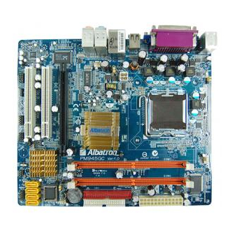
Page 9: Configuration
Mainboard PM945GC Configuration Layout of PM945GC... -
Page 10: Hardware Installation
Mainboard PM945GC Hardware Installation This section will assist you in quickly installing your system hardware. Wear a wrist ground strap before handling components. Electrostatic discharge may damage the system’s components. CPU Processor Installation ® ® ® ® ® This mainboard supports Intel... -
Page 11: Memory Installation: Dimm1/Dimm2
Memory Installation: DIMM1/DIMM2 The PM945GC provides two DIMM (Dual In-Line Memory Modules) sockets which allowing you to install 240-pin, unbuffered non-ECC, DDRII 667 (by overclocking)/ DDRII 533/ DDRII 400 SDRAMs. It also supports Dual Channel Technology and allows you installing a total memory capacity of 2 GB. - Page 12 Mainboard PM945GC How to enable Dual-Channel DDRII: These mainboards provide Dual-Channel functionality for the two DIMM sockets. Enabling Dual-Channel can significantly increase your data access rates. DIMM1 and DIMM2 share one channel. For enabling Dual-Channel, you have to install two memories in the DIMM sockets at the same time;...
-
Page 13: Back Panel Configuration
Mainboard PM945GC Back Panel Configuration PS/2 Mouse & PS/2 Keyboard Ports: KB/MS This mainboard provides a standard PS/2 mouse port and a PS/2 keyboard port. Serial and Parallel Interface Ports The mainboard provides one serial port and one parallel port on the back panel. - Page 14 Mainboard PM945GC Audio Ports: SOUND This mainboard provides six High Definition Audio ports for 8/6/4/2 channel playback capability. With jack sensing, auto detecting and adjusting, the device will make it easier to Plug and Play for you. Line-In(blue) This port is for audio input and connects to external audio devices such as CD player, tape player or other audio devices when the 8/6/4/2 channel audio effects driver is enabled.
-
Page 15: Front Panel Headers: Jw_Fp, Pwrled, Speak
Mainboard PM945GC Front Panel Headers: JW_FP, PWRLED, SPEAK JW_FP Assignment Function Assignment Function VCC5 (+) VCC5 (+) Hard Drive LED 2-pin Power LED (HDLED) (PWR LED) HDDLE (-) PWRLED (-) PWRBTN Power-on Button Reset Switch (PWRBTN) RSTSW (RESET) Hard Drive LED Header: HDLED If your case front panel has a hard drive LED cable, attach it to this header. -
Page 16: Connectors
Mainboard PM945GC Speaker Header: SPEAK A speaker cable on your case front panel can be attached to this header. When you reboot the computer, this speaker will issue a short audible (beep). If there are problems during the Power On Self-Test, the system will issue an irregular pattern of audible beeps through this speaker. -
Page 17: Headers & Jumpers
Mainboard PM945GC Headers & Jumpers Front USB Headers: USB2/3 These mainboards provide four onboard USB 1.1/2.0 ports (back panel) that attach to USB devices. There are two additional USB headers that can be connected by cables to four more USB ports on the front panel of your case giving you a possible eight USB ports. -
Page 18: Audio Configuration
Mainboard PM945GC Assignment Assignment USB Power On Disable (Default) Pin 1-2 Closed USB Power On Enabled +5VSB Pin 2-3 Closed Note: Close stands for putting a jumper cap onto two header pins. Clear CMOS Jumper: JBAT The “Clear CMOS” function is used when you are unable boot your system and need to reset the BIOS settings (CMOS settings) back to the manufacturer’s original settings. -
Page 19: Slots
Mainboard PM945GC Front Panel Audio Header: AUDIO If your case front panel has audio ports, you can connect them to the Front Audio Header of this mainboard. First, you must remove the jumper caps on this header and then attach the cables from the front panel to the pins on this header. -
Page 20: Power Supply Attachments
Mainboard PM945GC Power Supply Attachments ATX Power Connector: ATXPWR, ATX12V These mainboards provide two ATX power connectors, one 24-pin ATXPWR connector and one 4-pin ATX12V connector. You must use a power supply that has both of these connectors and both connectors must be attached before the system is powered on. -
Page 21: Chapter 2. Bios Setup
Mainboard PM945GC Chapter 2. BIOS Setup Introduction This section describes PHOENIX-AWARD™ BIOS Setup program which resides in the BIOS firmware. The Setup program allows users to modify the basic system configuration. The configuration information is then saved to CMOS RAM where the data is sustained by battery after power-down. -
Page 22: Main Menu
Mainboard PM945GC Main Menu Standard CMOS Features Include all the adjustable items in standard compatible BIOS. Advanced BIOS Features Include all the adjustable items of Award special enhanced features. Advanced Chipset Features Include all the adjustable items of chipset special features. -
Page 23: Thermal Throttling Options
Mainboard PM945GC PC Health Status It is for monitoring the system status such as temperature, voltage, and fan speeds. Thermal Throttling Options Set the function to low down the CPU temperature being at high workload to protect processor from damage or accidental shutdown when CPU temperature is over the value. -
Page 24: Chapter 3: Software Setup
Mainboard PM945GC Chapter 3: Software Setup Software List Category Platform ® Windows Vista/ XP/ 2000 Intel Chipset INF ® Windows Vista/ XP/ 2000 Realtek Lan Driver ® Windows Vista/ XP/ 2000 Realtek Audio Driver ® Windows Vista/ XP/ 2000 Intel VGA Driver ®... - Page 25 Mainboard PM945GC For Windows Vista Driver For Windows XP (64bit) Driver Attention ® Before you install the Realtek Audio Driver on Windows XP (64bit) ® operating system, please go to the Microsoft website to install the update for enabling HD Audio.
- Page 26 Mainboard PM945GC For Windows XP (32bit) Driver For Windows 2000 Driver...
- Page 27 Mainboard PM945GC Intel Chipset INF – It provides all drivers for the functions which built in both the Northbridge/ Southbridge. Intel VGA Driver – It provides the driver of Intel VGA. Realtek LAN Driver – It provides the driver of Realtek Network.
-
Page 28: Chapter 4: Troubleshooting
Mainboard PM945GC Chapter 4: Troubleshooting Problem 1: No power to the system. Power light does not illuminate. Fan inside power supply does not turn on. Indicator lights on keyboard are not lit. Causes: 1. Power cable is unplugged. 2. Defective power cable. - Page 29 Mainboard PM945GC Solutions: Back up data and applications files. Reformat the hard drive. Re-install applications and data using backup disks. Problem 5: Error message reading “SECTOR NOT FOUND” displays and the system does not allow certain data to be accessed.
- Page 30 Mainboard PM945GC Problem 11: No color on screen. Causes: 1. Faulty Monitor. 2. CMOS incorrectly set up. Solutions: 1. If possible, connect monitor to another system. If no color appears, replace monitor. 2. Call technical support. Problem 12: The screen displays “C: drive failure.”...
-
Page 31: Appendix I: 8/6/4/2 Channel Audio Effect Setup
Mainboard PM945GC Appendix I: 8/6/4/2 Channel Audio Effect Setup Channels Setup for Windows Vista After entering the system, click the audio icon from the Windows Vista screen. When your audio device is plugged, the system will detect it and show the “Speakers” tab automatically. - Page 32 Mainboard PM945GC Channels Setup for Windows XP After into the system, click the audio icon from the Windows XP screen. Click “Audio I/O” button, you can see the screen like the picture below. You can choose 2, 4, 6 or 8 channels by your speakers.
Need help?
Do you have a question about the PM945GC and is the answer not in the manual?
Questions and answers