Table of Contents
Advertisement
PM845GV1/ PM845GE1/
PM845GL1/ PM845GL1-533
Copyright
All rights reserved. No part of this publication may be reproduced, transmitted, transcribed,
stored in a retrieval system or translated into any language or computer language, in any
form or by any means, electronic, mechanical, magnetic, optical, chemical, manual or
otherwise, without the prior written permission of the company. Brands and product names
are trademarks or registered trademarks of their respective companies.
The vendor makes no representations or warranties with respect to the contents herein and
especially disclaims any implied warranties of merchantability or fitness for any purpose.
Further the vendor reserves the right to revise this publication and to make changes to the
contents herein without obligation to notify any party beforehand. Duplication of this
publication, in part or in whole, is not allowed without first obtaining the vendor's approval
in writing.
Disclaimer
We make no warranty of any kind with regard to the content of this user's manual and it is
subject to be changed without notice and we will not be responsible for any mistakes found
in this user's manual. All the brand and product names are trademarks of their respective
companies.
FCC Compliance Statement
This equipment has been tested and found to comply with the limits of a Class B digital
device, pursuant to Part 15 of the FCC Rules. These limits are designed to provide
reasonable protection against harmful interference in a residential installation. This
equipment generates, uses and can radiate radio frequency energy and, if not installed and
used in accordance with the instructions, may cause harmful interference to radio
communications. Operation of this equipment in a residential area is likely to cause harmful
interference in which case the user will be required to correct the interference at his own
expense. However, there is no guarantee that interference will not occur in a particular
installation.
120410023M1N
Advertisement
Table of Contents

Related Manuals for Albatron PM845GV1


Summary of Contents for Albatron PM845GV1
- Page 1 PM845GV1/ PM845GE1/ PM845GL1/ PM845GL1-533 Copyright All rights reserved. No part of this publication may be reproduced, transmitted, transcribed, stored in a retrieval system or translated into any language or computer language, in any form or by any means, electronic, mechanical, magnetic, optical, chemical, manual or otherwise, without the prior written permission of the company.
- Page 2 Threading Technology! * Note: PM845GE1 supports only 4X, 1.5V AGP cards. Installing any other AGP card may damage some of the components. * Note: The PM845GV1/ PM845GL1/ PM845GL1-533 supports only ADD cards. You cannot install AGP cards on these mainboards!!
-
Page 3: Table Of Contents
Contents CHAPTER 1. INTRODUCTION........1 ................1 NTRODUCTION ................1 PECIFICATION ................5 ONFIGURATION ............11 ANEL ONFIGURATION CHAPTER 2. BIOS SETUP .......... 20 ................20 NTRODUCTION .................. 22 ..............24 DVANCED EATURES ................29 ERIPHERALS ................32 OWER HW M ................. -
Page 4: Chapter 1. Introduction
Introduction Congratulations for choosing from the recent line of high performance mainboards: the PM845GV1/ PM845GE1/ PM845GL1/ PM845GL1-533. These mainboards were designed to take advantage of the latest industry technology to provide you with the ultimate solution in data processing. In the tradition of its predecessors, these mainboard continue a commitment to reliability and performance and strives for full compliance and compatibility with industry software and hardware standards. -
Page 5: Graphics Controller
Intel Digital Video (DVO) ports support digital displays and TV-out Integrated 350MHz RAMDAC PM845GV1/ PM845GE1/ PM845GL1/ PM845GL1-533 analog port utilizes an integrated 350 MHz RAMDAC that can enhance the resolution of a standard progressive scan analog monitor to 2048x1536 pixels with 32-bit color at 60Hz. -
Page 6: Universal Serial Bus
PM845GV1/ PM845GE1/ PM845GL/1 PM845GL1-533 Accelerated Graphics Port interface PM845GE1 supports a single, 1.5V, AGP 2.0 compliant device PM845GV1/ PM845GL1/ PM845GL1-533 supports ADD cards only Green Functionality Supports PHOENIX-AWARD™ BIOS power management functionality Wakes from power saving sleep mode with any keyboard or mouse activity... -
Page 7: Watch Dog Timer
PM845GV1/ PM845GE1/ PM845GL/1 PM845GL1-533 I/O facilities One multi-mode Parallel Port capable of supporting the following specifications: 1. Enhanced Parallel Port (EPP) 2. Extended Capabilities Port (ECP) 3. PS/2 compatible bi-directional parallel port One serial port, 16550 UART with 16-byte send/receive FIFOs... -
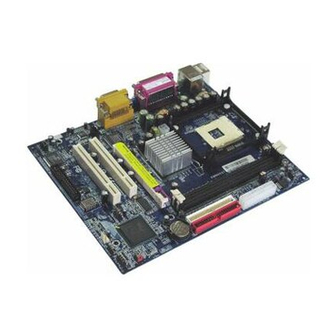
Page 8: Configuration
PM845GV1/ PM845GE1/ PM845GL/1 PM845GL1-533 Configuration Layout of PM845GV1 KB/MS CPUFAN USB/LAN Socket 478 PRT/COM/VGA ATX_12V Intel 82845GV SOUND Winbond IDE1 IDE2 W83627HF CD-IN BAT1 Codec PCI1 Intel 82801DB USB2 PCI2 CASE OPEN 3COM BIOS CHASFAN SW/LED SPDIF SPEAKER... - Page 9 PM845GV1/ PM845GE1/ PM845GL/1 PM845GL1-533 Layout of PM845GE1 KB/MS CPUFAN USB/LAN Socket 478 PRT/COM/VGA ATX_12V Intel 82845GE SOUND Winbond IDE1 IDE2 W83627HF CD-IN BAT1 Codec PCI1 Intel 82801DB USB2 PCI2 CASE OPEN 3COM BIOS CHASFAN SW/LED SPDIF SPEAKER...
- Page 10 PM845GV1/ PM845GE1/ PM845GL/1 PM845GL1-533 Layout of PM845GL1/ PM845GL1-533 KB/MS CPUFAN USB/LAN Socket 478 PRT/COM/VGA ATX_12V Intel 82845GL SOUND Winbond IDE1 IDE2 W83627HF CD-IN BAT1 Codec PCI1 Intel 82801DB USB2 PCI2 CASE OPEN 3COM BIOS CHASFAN SW/LED SPDIF SPEAKER...
-
Page 11: Cpu Processor Installation
PM845GV1/ PM845GE1/ PM845GL/1 PM845GL1-533 CPU Processor Installation ® ® This mainboard supports Intel Pentium 4 processors using a Socket-478. Before installation of your CPU, we suggest you visit the Intel website and review the processor installation procedures. http://www.intel.com CPU Socket-478 Configuration Steps: 1. -
Page 12: Fan Headers
PM845GV1/ PM845GE1/ PM845GL/1 PM845GL1-533 Fan Headers There are two power headers used for cooling fans, which play an important role in maintaining the ambient temperature in your system . Warning: This system has a BIOS configuration feature that issues a warning when the CPU fan is not plugged in or is not functioning. -
Page 13: Memory Configuration
PM845GV1/ PM845GE1/ PM845GL/1 PM845GL1-533 Memory Configuration The PM845GV1/ PM845GE1/ PM845GL1/ PM845GL1-533 contains 2 sockets for 184- pin DDR SDRAM with a total memory capacity of up to 2GB. You can install DDR 333/ 266 (PC 2700/ 2100) SDRAM for PM845GE1, and DDR 266/ 200 (PC 2100/ 1600) SDRAM for PM845GV1/ PM845GL1/ PM845GL1-533. -
Page 14: Back Panel Configuration
PM845GV1/ PM845GE1/ PM845GL/1 PM845GL1-533 Back Panel Configuration Game Port Printer Port Speaker Out PS/2 Mouse Line In PS/2 Keyboard Mic In COM1 PS/2 Mouse & PS/2 Keyboard Connectors: KB/MS This mainboard provides a standard PS/2 mouse connector and PS/2 Keyboard connector. -
Page 15: Serial And Parallel Interface Ports
PM845GV1/ PM845GE1/ PM845GL/1 PM845GL1-533 Serial and Parallel Interface Ports This system comes equipped with two serial ports and one parallel port. The Serial Interface: COM1 The serial interface port is sometimes referred to as an RS-232 port or an asynchronous communication port. -
Page 16: Connector Configuration
PM845GV1/ PM845GE1/ PM845GL/1 PM845GL1-533 Connector Configuration KB/MS CPUFAN USB/LAN Socket 478 PRT/COM/VGA ATX_12V Intel 82845GV SOUND Winbond IDE1 IDE2 W83627HF CD-IN BAT1 Codec PCI1 Intel 82801DB USB2 PCI2 CASE OPEN 3COM BIOS CHASFAN SW/LED SPDIF SPEAKER SPEAKER SW/LED USB2 CASE OPEN... - Page 17 PM845GV1/ PM845GE1/ PM845GL/1 PM845GL1-533 Front Panel Indicators: SW/LED Pin Assignment Function Pin Assignment Function HD LED (+) ACPI LED (+) Hard Drive POWER LED HD LED (-) ACPI LED (-) Reset SW (-) Power SW(+) Power-on Reset Switch Switch Reset SW (+)
- Page 18 PM845GV1/ PM845GE1/ PM845GL/1 PM845GL1-533 Front USB Headers: USB2 You can attach a bracket cables to the USB2 header. Then you may connect your USB devices to the bracket. * Microsoft has not published the USB 2.0 driver for Windows 9X/ ME, if your OS is ®...
-
Page 19: Power Supply Attachments
PM845GV1/ PM845GE1/ PM845GL/1 PM845GL1-533 Floppy Disk Connector: FDC The mainboard provides a standard floppy disk connector (FDC) that supports 360K, 720K, 1.2M, 1.44M and 2.88M floppy disk types. This connector supports the provided floppy drive ribbon cables provided. Hard Disk Connectors: IDE1/IDE2 This mainboard has a 32-bit Enhanced PCI IDE Controller that provides PIO Mode 0~4, Bus Master, and Ultra DMA/33, Ultra DMA/66, Ultra DMA/100, functionality. - Page 20 DVO devices (e.g. TMDS, LVDS and TV-OUT). If you try to install the other graphics cards onto the AGP slot of PM845GV1/ PM845GL1/ PM845GL1-533, the display would be not correctly. Use the onboard VGA or install an ADD card.
-
Page 21: Audio Connectors
PM845GV1/ PM845GE1/ PM845GL/1 PM845GL1-533 Audio Connectors This mainboard provides three connectors as part of its audio Subsystem. KB/MS CPUFAN USB/LAN Socket 478 PRT/COM/VGA ATX_12V Intel 82845GV SOUND Winbond IDE1 IDE2 W83627HF CD-IN BAT1 Codec PCI1 Intel 82801DB USB2 PCI2 CASE OPEN... - Page 22 PM845GV1/ PM845GE1/ PM845GL/1 PM845GL1-533 CD-ROM Audio-In Header: CD-IN This header is used to connect a CD Audio Cable from a CD-ROM / DVD drive to the onboard audio subsystem. Assignment Assignment Left Channel Input Right Channel Input S/PDIF Connector: SPDIF S/PDIF (Sony/Philips Digital Interface) is a recent audio transfer file format, which provides high quality audio using optical fiber and digital signals.
-
Page 23: Chapter 2. Bios Setup
PM845GV1/ PM845GE1/ PM845GL/1 PM845GL1-533 Chapter 2. BIOS Setup Introduction This section describes the PHOENIX-AWARD™ BIOS Setup program which resides in the ROM BIOS firmware. The Setup program allows users to modify the basic system configurations. The configuration information is then saved to CMOS RAM where the data is sustained by battery after power-down. -
Page 24: Supported Cpus
PM845GV1/ PM845GE1/ PM845GL/1 PM845GL1-533 DRAM Support DDR (Double Data Rate) SDRAM (Synchronous DRAM) is supported. Supported CPUs ® ® This PHOENIX-AWARD™ BIOS supports the Intel Pentium 4 CPUs. Key Function In general, use the arrow keys to highlight items, press <Enter> to select, use the <PgUp>... -
Page 25: Main Menu
PM845GV1/ PM845GE1/ PM845GL/1 PM845GL1-533 Main Menu When you enter the PHOENIX-AWARD™ BIOS Utility, the Main Menu will appear on the screen then Main menu allows you to select from several configuration options. Use the left/right arrow keys to select a particular configuration screen from the top menu bar... - Page 26 PM845GV1/ PM845GE1/ PM845GL/1 PM845GL1-533 Main Menu Setup Selections Item Options Description Set system date. Note that the Date mm:dd:yy ‘Day’ automatically changes when you set the date. Time hh: mm: ss Set current time of the system. Options are in its Press <Enter>...
-
Page 27: Advanced Features
PM845GV1/ PM845GE1/ PM845GL/1 PM845GL1-533 Advanced Features Advanced Features First /Second/Third Boot Device Select the order in which devices will be searched in order to find a boot device. Options: Floppy, LS120, HDD-0, SCSI, CDROM, HDD-1, HDD-2, HDD-3, ZIP100, USB-FDD, USB-ZIP, USB-CDROM, USB-HDD, LAN, Disabled. -
Page 28: Advanced Bios Features
Options: Enabled (default), Disable. CPU Hyper-Threading (this item only displays if you are using the PM845GV1 or GE1 with a CPU that supports HT) Use this field to enable or disable Hyper-Threading. Options: Disabled (default), Enabled. Quick Power On Self Test Allows the system to skip certain tests while booting. -
Page 29: Apic Mode
Turbo Mode (only for PM845GV1) Allows you to activate the turbo mode. Options: Disabled (default), Enabled. Memory Frequency For This option allows you to set the memory frequency. Options of PM845GE1: Default, DDR 333, 266, for PM845GV1/ PM845GL1/ PM845GL1-533: Default, DDR 266, 200. -
Page 30: System Bios Cacheable
PM845GV1/ PM845GE1/ PM845GL/1 PM845GL1-533 System BIOS Cacheable When enabled, access to the system BIOS ROM addressed at F0000H-FFFFFH are cached, provided that the cache controller is enabled. Options: Enabled (default), Disabled. Video BIOS Cacheable Select “Enable” to cache video BIOS, resulting in better system performance. If any program writes to this memory area, a system error may result. -
Page 31: Resources Controlled By
PM845GV1/ PM845GE1/ PM845GL/1 PM845GL1-533 Resources Controlled By BIOS can automatically configure all the boot and Plug & Play compatible devices. If you choose Auto, you cannot select IRQ DMA and memory base address fields, since BIOS automatically assigns them. Options: Auto<ESCD> (default)、Manual. -
Page 32: Peripherals
PM845GV1/ PM845GE1/ PM845GL/1 PM845GL1-533 Peripherals INTEL OnChip IDE Device Highlight this field and press “Enter”, it will take you a submenu with following options: On-Chip Primary / Secondary PCI IDE This item allows you to enable / disable the on-chip primary / secondary PCI IDE. -
Page 33: Usb Controller
With systems that have multiple video cards, this option determines whether the primary display uses a PCI Slot or onboard/AGP (onboard). PM845GE1 => Options: PCI Slot, Onboard/AGP (default) PM845GV1/ PM845GL1/ PM845GL1-533=> Options: PCI Slot, Onboard (default) Onboard I/O Chip Setup PWRON After PWR-Fail This field will determine whether your system will boot after restoring power after a power failure. -
Page 34: Hot Key Power On
PM845GV1/ PM845GE1/ PM845GL/1 PM845GL1-533 HOT Key Power ON This option allows you to use the Ctrl key along with a hot key (function key) to power on your system. Options: Ctrl – F1, Ctrl – F2, Ctrl – F3, … to Ctrl – F12. -
Page 35: Power Menu
PM845GV1/ PM845GE1/ PM845GL/1 PM845GL1-533 Power Menu The Power Management Setup Menu allows you to configure your system to utilize energy conservation and power up/power down features. ACPI Suspend Type The item allows you to select the suspend type under the ACPI operating system. -
Page 36: Video Off Method
PM845GV1/ PM845GE1/ PM845GL/1 PM845GL1-533 Video Off Method This option determines the manner in which the monitor is goes blank. Options: 1. Blank Screen (default): This option only writes blanks to the video buffer. 2. V/H SYNC+Blank: This selection will cause the system to turn off the vertical and horizontal synchronization ports and write blanks to the video buffer. -
Page 37: Usb Kb Wake Up From S3
PM845GV1/ PM845GE1/ PM845GL/1 PM845GL1-533 RTC Wake Up When “Enabled”, you can set the date and time at which the RTC (real-time clock) alarm awakens the system from Suspend mode. For Windows based system, if you have scheduled any tasks as part of the “Scheduled Tasks” function, RTC Wake Up will be disabled. -
Page 38: Hw Monitoring
PM845GV1/ PM845GE1/ PM845GL/1 PM845GL1-533 HW Monitoring Case Open Warning If this function is set to “Enabled” and the case had been previously opened, the system will automatically display alert messages on the screen when you power on your computer. If this function is set to “Disabled”, the system will not show alert messages when you power your computer even if the case is opened by others. -
Page 39: Exit Menu
PM845GV1/ PM845GE1/ PM845GL/1 PM845GL1-533 Load System Default settings Load system Default settings. Load System Turbo Settings Load system Turbo Settings. Load CMOS From BIOS Load defaults from flash ROM from the systems without batteries. Save CMOS To BIOS Save defaults to flash ROM for systems without batteries. -
Page 40: Chapter 3. Software Setup
You can also launch the Driver CD Installation Utility manually: 1. The Driver CD Installation Utility will display. Click the button which corresponds to the model of your mainboard, e.g.:“PM845GV1/ PM845GE1”. Note: The screens are for your reference only and may vary slightly according to the... - Page 41 PM845GV1/ PM845GE1/ PM845GL/1 PM845GL1-533 2. The next screen displays three options: Mainboard Driver, Tools, and Browse CD. Click “Mainboard Driver”. 3. This next screen displays a list of available software drivers. Click the driver you wish to install. ® ®...
- Page 42 PM845GV1/ PM845GE1/ PM845GL/1 PM845GL1-533 4. From the screen in step 2, click the “Tools” button. The next screen will display two programs to install. Follow the instructions after clicking the button if you need to install the software. Note: you can click “Back” to go to the previous page, or click “Exit” to exit the...
-
Page 43: Chapter 4. Troubleshooting
PM845GV1/ PM845GE1/ PM845GL/1 PM845GL1-533 Chapter 4. Troubleshooting Problem 1: No power to the system. Power light does not illuminate. Fan inside power supply does not turn on. Indicator lights on keyboard are not lit. Causes: 1. Power cable is unplugged. - Page 44 PM845GV1/ PM845GE1/ PM845GL/1 PM845GL1-533 Problem 4: System only boots from the CD-ROM. The hard disk can be read and applications can be used but booting from the hard disk is impossible. Causes: Hard Disk boot sector has been corrupted. Solutions: Back up data and applications files. Reformat the hard drive. Re-install applications and data using backup disks.
- Page 45 PM845GV1/ PM845GE1/ PM845GL/1 PM845GL1-533 Problem 10: Keyboard failure. Causes: Keyboard is disconnected. Solutions: Reconnect keyboard. Replace keyboard if you continue to experience problems. Problem 11: No color on screen. Causes: 1. Faulty Monitor. 2. CMOS incorrectly set up. Solutions: 1. If possible, connect monitor to another system. If no color appears, replace monitor.
Need help?
Do you have a question about the PM845GV1 and is the answer not in the manual?
Questions and answers