Table of Contents
Advertisement
PX915PC/ PX915GC Series
Copyright
All rights are reserved. No part of this publication may be reproduced, transmitted, transcribed,
stored in a retrieval system or translated into any language or computer language, in any form or by
any means, electronic, mechanical, magnetic, optical, chemical, manual or otherwise, without the
prior written permission of the company. Brands and product names are trademarks or registered
trademarks of their respective companies.
The vendor makes no representations or warranties with respect to the contents herein and especially
disclaim any implied warranties of merchantability or fitness for any purpose. Further the vendor
reserves the right to revise this publication and to make changes to the contents herein without
obligation to notify any party beforehand. Duplication of this publication, in part or in whole, is not
allowed without first obtaining the vendor's approval in writing.
Trademark
All the trademarks or brands in this document are registered by their respective owner.
Disclaimer
We make no warranty of any kind with regard to the content of this user's manual. The content is
subject to change without notice and we will not be responsible for any mistakes found in this user's
manual. All the brand and product names are trademarks of their respective companies.
FCC Compliance Statement
This equipment has been tested and found to comply with the limits of a Class B digital device,
pursuant to Part 15 of the FCC Rules. These limits are designed to provide reasonable protection
against harmful interference in a residential installation. This equipment generates, uses and can
radiate radio frequency energy and, if not installed and used in accordance with the instructions, may
cause harmful interference to radio communications. Operation of this equipment in a residential area
is likely to cause harmful interference in which case the user will be required to correct the
interference at his own expense. However, there is no guarantee that interference will not occur in a
particular installation.
CE Mark
The device is in accordance with 89/336 ECC-ENC Directive.
Important, please read!!!
Ver: TC101
120410127M1N
Advertisement
Table of Contents

Related Manuals for Albatron PX915PC PRO-G


Summary of Contents for Albatron PX915PC PRO-G
- Page 1 PX915PC/ PX915GC Series Copyright All rights are reserved. No part of this publication may be reproduced, transmitted, transcribed, stored in a retrieval system or translated into any language or computer language, in any form or by any means, electronic, mechanical, magnetic, optical, chemical, manual or otherwise, without the prior written permission of the company.
-
Page 2: Package Contents
The images and pictures in this manual are for reference only and may vary slightly from actual product installation depending on specific hardware models, third party components and software versions. Unplug your computer when installing components and configuring switches and pins. This mainboard contains very delicate IC chips. -
Page 3: User Manual
Intel 915P/ 915G & ICH6 ® Supports Socket 775 Intel Pentium ® ® Prescott Processor User Manual Enabling Hyper-Threading for your computer system requires ALL of the following components CPU: An Intel Pentium 4 Processor with HT Technology ® ® Chipset: An Intel ®... -
Page 4: Table Of Contents
......................1 NTRODUCTION ......................2 PECIFICATION ....................... 5 ONFIGURATION Layout of PX915PC PRO-G................. 5 Layout of PX915PC PRO..................6 Layout of PX915PC....................7 Layout of PX915GC PRO-G ................8 Layout of PX915GC PRO ..................9 Layout of PX915GC................... 10 ..................11... -
Page 5: Chapter 1. Getting Started
Introduction Congratulations on choosing from the PX915PC/PX915GC series of mainboards! The PX915PC series includes the PX915PC PRO-G, PX915PC PRO and the PX915PC. The PX915GC series includes the ® PX915GC PRO-G, PX915GC PRO and the PX915GC. These mainboards are based on the Intel 915P/915G ®... -
Page 6: Specification
Southbridge Chipset – Intel® ICH6 I/O Controller – Winbond W83627THF HD Aduio Codec – Realtek ALC880 Gb LAN Controller – Marvell® MV8001 (for PX915PC PRO-G/ PX915GC PRO-G) Mb LAN Controller – VIA® VT6105 (for PX915PC PRO / PX915GC PRO) DRAM Memory:... - Page 7 Supports Sony/ Philips Digital Interfaces (S/PDIF) LAN Controller: The PX915PC PRO-G and PX915GC PRO-G provide a LAN facility using a built-in Marvell® MV8001 chipset which supports Ethernet 10/100/1000 Mbit/s connectivity. The PX915PC PRO and PX915GC PRO provide an additional LAN facility using a built-in VIA®...
-
Page 8: Watch Dog Timer
PX915PC/ PX915GC Series Supports 3D Acceleration Supports Video Acceleration ® Micorsoft DirectX compatible OpenGL driver available I/O facilities: One multi-mode Parallel Port capable of supporting the following specifications: 1. Standard & Bi-direction Parallel Port 2. Enhanced Parallel Port (EPP) 3. Extended Capabilities Port (ECP) Contains one serial port, 16550 UART Contains one VGA port (PX915GC series only) Supports Infrared Data Transmissions using IrDA... -
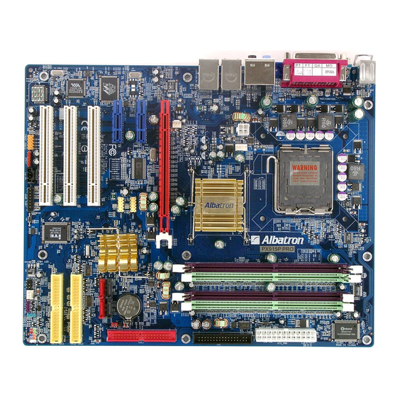
Page 9: Configuration
PX915PC/ PX915GC Series Configuration Layout of PX915PC PRO-G... -
Page 10: Layout Of Px915Pc Pro
PX915PC/ PX915GC Series Layout of PX915PC PRO... -
Page 11: Layout Of Px915Pc
PX915PC/ PX915GC Series Layout of PX915PC... -
Page 12: Layout Of Px915Gc Pro-G
PX915PC/ PX915GC Series Layout of PX915GC PRO-G... -
Page 13: Layout Of Px915Gc Pro
PX915PC/ PX915GC Series Layout of PX915GC PRO... -
Page 14: Layout Of Px915Gc
PX915PC/ PX915GC Series Layout of PX915GC... -
Page 15: Hardware Installation
PX915PC/ PX915GC Series Hardware Installation This section will assist you in quickly installing your system hardware. Wear a wrist ground strap before handling components. Electrostatic discharge may damage the system’s components. CPU Processor Installation ® ® This mainboard supports Intel Pentium 4 processors using a Socket 775. -
Page 16: Fan Headers
PX915PC/ PX915GC Series FAN Headers Three power headers are available for the cooling fans. Cooling fans play an important role in maintaining the ambient temperature in your system. Attention: We strongly recommend that you use a CPU fan sink with your CPU. You can attach the power cable from the CPU fan sink to the CPUFAN Header. -
Page 17: Back Panel Configuration
PX915PC/ PX915GC Series DIMM4 share the second channel. Enabling Dual-Channel simply means to make sure that the total memory for the two channels are balanced. For example: If you install one 256 MB module in DIMM1 and one in DIMM2 (256MB x 2 = 512MB), you must install a total of 512 MB between DIMM3 and DIMM4. In balancing the memory on the two channels, you have, in effect, enabled Dual-Channel. -
Page 18: Connectors
PX915PC/ PX915GC Series Configuration PS/2 Mouse & PS/2 Keyboard Connectors: KB/MS These mainboards provide a standard PS/2 mouse connector and PS/2 keyboard connector. The pin assignments are described below: PS/2 Mouse Assignment Assignment Data +5 V (fused) No connect Clock Ground No connect PS/2 Keyboard... - Page 19 These mainboards come with 4 USB ports. The USB connectors are used to attach to keyboards, mice and other USB devices. You can plug the USB devices directly into this connector. The PX915PC PRO-G and PX915GC PRO-G have a 10/100/1000 Mbit/s LAN port. And the PX915PC PRO and PX915GC PRO have an additional 10/100 Mbit/s LAN port.
-
Page 20: Front Panel Indicator: Sw/Led、Pwrled、Speaker
PX915PC/ PX915GC Series nectors Floppy Disk Connector: FDC These mainboards provide a standard floppy disk connector (FDC) that supports 360K, 720K, 1.2M, 1.44M and 2.88M floppy diskette drives. This connector supports the floppy drive ribbon cables provided in the packaging. Hard Disk Connectors: IDE1/ SATA1-4 These mainboards provide a standard IDE connector that supports PIO Mode 0~4, Bus Master, Ultra ATA 66/100. - Page 21 PX915PC/ PX915GC Series Indicator: SW/LED、PWRLED、SPEAKER HD LED (Hard Drive LED Connector/ red) This connector can be attached to an LED on the front panel of a computer case. The LED will flicker during any disk activity. RST SW (Reset Connector/ blue) This connector can be attached to a momentary SPST switch.
-
Page 22: Headers & Jumpers
PX915PC/ PX915GC Series Headers & Jumpers Infrared Header: IrDA You can attach an infrared device to this connector and use this connector for connectionless infrared data transfers. Game Port Header: GAME PORT There is a game port header on these mainboards. To use this header, you must attach a game port bracket-cable so that you can interface... -
Page 23: Audio Connectors
PX915PC/ PX915GC Series Clear CMOS Jumper: JP1 The “Clear CMOS” jumper allows you to reset your CMOS configurations. This is particularly useful when you have forgotten your system password and cannot boot to the operating system. The following steps explain how to reset your CMOS configurations when you have forgotten your system password. - Page 24 PX915PC/ PX915GC Series dio Connectors CD-ROM Audio-In Header: CD-IN This header is used to connect to the CD-ROM/DVD audio cable Front Panel Audio Header (Orange): FRONT AUDIO You can use the Front Panel Audio header (FRONT AUDIO) to connect to a separate audio bracket or to connect to case embedded audio equipment.
-
Page 25: Slots
PX915PC/ PX915GC Series S/PDIF Header (Red): SPDIF S/PDIF (Sony/Philips Digital Interface) is an audio transfer file format which provides high quality audio using optical fiber and digital signals. This mainboard is equipped with an SPDIF header and must be used with a bracket-cable containing S/PDIF ports. An SPDIF/Audio bracket is optionally packaged with some models. -
Page 26: Power Supply Attachments
PX915PC/ PX915GC Series PCI-Express slots: PCI-E X16 & PCI-E1/ PCI-E2 PCI-E x16 slots are for installing PCI-Express graphics cards. The PCI-E x1 slot is for expansion cards which fit the PCI-E x1 slot. PCI Slots: PCI1/ PCI2/ PCI3 This mainboard is equipped with 3 standard PCI slots. PCI stands for Peripheral Component Interconnect and is a bus standard for expansion cards, which has, for the most part, supplanted the older ISA bus standard. -
Page 27: Chapter 2. Bios Setup
PX915PC/ PX915GC Series Chapter 2. BIOS Setup Introduction his section describes PHOENIX-AWARD™ BIOS Setup program which resides in the BIOS firmware. The Setup program allows users to modify the basic system configura tion. The configuration information is then saved to CMOS RAM where the data is sustained by battery after power-down. -
Page 28: Main Menu
PX915PC/ PX915GC Series Key Function In general, you can use the arrow keys to highlight items, press <Enter> to select, use the <PgUp> and < PgDn> keys to change entries, press <F1> for help and press <Esc> to quit. The following table provides more detail about how to navigate within the BIOS Setup program. -
Page 29: Main Menu Setup Configuration Options
PX915PC/ PX915GC Series particular configuration screen from the top menu bar or use the down arrow key to access and nfigure the information below. Main Menu Setup Configuration Options... -
Page 30: Advanced Bios Features
PX915PC/ PX915GC Series Item Options Description Set the system date. Note that the ‘Day’ automatically Date mm dd yyyy changes when you set the date. Time Hh: mm: ss Set the current time of the syst IDE Channel 0/1 Options contained in Press <Enter>... -
Page 31: Removable Device Priority
PX915PC/ PX915GC Series Removable Device Priority lect removable device priority. Just like floppy, LS120, ZIP-100, USB-FDD and USB-ZIP. ard Disk Boot Priority lect hard disk boot priority. CD-ROM Boot Priority Select CD-ROM boot priority. First /Second/Third Boo t Device Select the order in which devic es will be searched in order to find a boot device. -
Page 32: Thermal Management
PX915PC/ PX915GC Series Options: 4 Min、8 Min、16 Min (default)、32 Min Thermal Management This item will monit or the CPU thermal to preve nt the CPU damage with high temperature. Limit CPUID MaxVal When the limit CPUID MaxVal is set to 3, the item s hould be set to “Disabled”... -
Page 33: Apic Mode
PX915PC/ PX915GC Series Options: 6 (default)、8、10、12、15、20、24、30 Typematic Delay (Msec) The delay before keystrokes begin to r epeat. Options: 250 (default)、500、750、1000 APIC Mode By enabling this option, “MPS version control for OS” can be config ured. Options: Disabled、Enabled (default) MPS Version Control For O The 1.1 version is the older version that supports 8 more IRQs in the Windows NT environm ent. -
Page 34: Video Bios Cacheable
PX915PC/ PX915GC Series DRAM RAS# to CAS# Delay This item allows you to select a delay time between the CAS and RAS strobe signals. It only applies when DRAM is written to, read from, or refreshed. This field is adjustable only when “DRAM Timing Selectable”... -
Page 35: Reset Configuration Data
PX915PC/ PX915GC Series **VGA Setting** (only for onboard VGA) PEG Force X1 This item allows you to force the PCI-Express x 16 slot to install the PCI- Express x 1 interface expansion card. Options: Disabled (default)、 Enabled On-Chip Frame Buffer Size This setting is for pure DOS mode using, you can set 1MB or 8MB to share the system mem ory. -
Page 36: Spread Spectrum
PX915PC/ PX915GC Series Options: IRQ-3/ 4/ 5/ 7/ 9/ 10/ 11/ 12/ 14/ 15 assigned to PCI device PCI / VGA Palette Snoop Some graphic controllers that are not VGA compatible take the outpu t from a VGA controller and map to their display as a way to provide boot information and VGA compatibility. -
Page 37: Integrated Peripherals
PX915PC/ PX915GC Series CPU Speed Detected This item displays the default CPU speed. CPU Speed Setting This item display the CPU spee d that you setting for. If you don’t change the “CPU Host Frequency” or the “CPU Clock tio” and the item will display the current CPU speed. -
Page 38: Init Display First
PX915PC/ PX915GC Series Init Display First With systems that have multiple video cards, this option determines whether the primary display uses a PCI slot or an AGP slot. Options: PCIEx (default)、PCI Slot OnChip IDE Device IDE HDD Block Mode Block mode is otherwise known as block transfer, multiple commands, or multiple sector read/write. Select the “Enabled”... -
Page 39: Pata Ide Mode
PX915PC/ PX915GC Series Disabled Disable on-chip serial ATA. No Serial ATA devices installed. Auto(default) BIOS will auto-detect the presence of any SATA devices. 2 (or 1) IDE drivers + 4 (or 3) SATA drivers Enhanced Mode 2 (or 1) IDE drivers + 2 (or 1) SATA drivers (Must connect with SATA1 +3 or with TA2+4) Combined Mode 4 ( or 3 or... -
Page 40: Power On Function
PX915PC/ PX915GC Series Audio Device This item allows you to control the onboard audio. Options: Auto (default)、Disabled 10/100 Mb LAN Device This item allows you to enable or disab le the 10/ 100 Mb LAN Device. Options: Enabled (default)、 isabled Gigabit LAN Device This item allows you to enable or disable the Gigabit LAN Device. -
Page 41: Ir Transmission Delay
PX915PC/ PX915GC Series IR Transmission Delay This item allows you to enable/disable IR transmission delay. This field only configurable if “UART Mode Select” is set to “ASKIR” or “IrDA”. Options: Enabled (default)、Disabled UR2 Duplex Mode Select the transmission mode used by the IR interface. Full-duplex mode permits simultaneous bi-directional transmission. -
Page 42: Power Management
PX915PC/ PX915GC Series PWRON After PWR-Fail This field will determine whether your system will boot after restoring power after a po wer failure. If you select “ On”, the system will boot whether or not the system was on before wer failure. -
Page 43: Acpi Suspend Type
PX915PC/ PX915GC Series ACPI Suspend Type The item allows you to select the suspend type using the ACPI operating system. ptions: (POS) (default) Power on Suspend (STR) Suspend to RAM & S3 POS and STR Run VG ABIOS if S3 Resume lect whether you want to run VGABIOS when the system wakes up from the S3 suspend function. -
Page 44: Suspend Type
PX915PC/ PX915GC Series Suspend Type This item allows you to select the suspend type under the ACPI operating system. Options: Stop Grant (default)、PwrOn Suspend Modem Use IRQ This determines the modem’s IRQ. Options: 3 (default)、4、5、7、9、10、11、NA. Suspe nd Mode This item allows you to select the suspend time under the ACPI operating system. Options: Disabled(default)、... -
Page 45: Hardware Monitor
PX915PC/ PX915GC Series RTC Wake Up When “Enabled”, you can set the date and time at which the RTC (real-time clock) alarm awakens the system from Suspend mode. Options: Enabled、Disabled (default). Date (of Month) Ala You can choose which date of the month the system will boot up. This field is only configurable when “RTC Wake Up”... -
Page 46: Load Defaults
PX915PC/ PX915GC Series Smart CPUFAN Temperature his function allows you to select the CPU temperature. If the CPU temperature is higher than the lue you’ve selected, the CPUFAN will accelerate till the temperature cools down to the defaulted lue you set. ptions: Disabled (default)、30 C / 86 F、35... -
Page 47: Exit Menu
PX915PC/ PX915GC Series Load CMOS From BIOS ad defaults from flash ROM for systems without batteries. Save CM OS To BIOS ve defaults to flash ROM for systems without batteries. Exit Menu Save & Exit Se Save all configuration ch anges to CMOS (memory) and exit setup. -
Page 48: Chapter 3: Software Setup
Intel onboard VGA Driver (only for PX915GC series) Windows 2000 /XP VIA Network Driver (for PX915PC PRO/GC PRO) Windows 98 /ME /2000 /XP Marvell Network Driver (for PX915PC PRO-G/ Windows 98 /ME /2000 /XP PX915GC PRO-G) Trend PC-Cillin Windows 98 /ME /2000 /XP... - Page 49 PX915PC/ PX915GC Series PX915PC/ PX915GC Series Intel Chi pset INF – provides all the drivers of the functions that built in the Northbridge/ Southbridg Realtek A udio Driver – provides the driver of Realtek H D Audio Codec Note:You can only install this driver if you are using Windows®...
- Page 50 PX915PC/ PX915GC Series Virtual Cable Tester – provides Virtual Cable Tester for Gb LAN connection testing 3. If you click the “Browse CD” button from the screen in step 1, you can browse all the files in the Driver CD. 4.
-
Page 51: Chapter 4: Troubleshooting
PX915PC/ PX915GC Series Chapter 4: Troubleshooting blem 1: power to the system. Power light does not illuminate. Fan inside power supply does not turn on. Indicator lights on keyboard are not lit. auses: . Power cable is unplugged. . Defective power cable. . - Page 52 PX915PC/ PX915GC Series Problem 4: System only boots from the CD-ROM. The hard disk can be read and applications can be used but booting from the hard disk is impossible. Causes: Hard Disk b oot sector has been corrupted. Solutions: Back up data and a pplications files.
- Page 53 PX915PC/ PX915GC Series Problem 10: Keyboard failure. Causes: Keyboard is disconnected. Solutions: Recon nect keyboard. Replace keyboard if you continue to experience problems. Problem 11: No color on screen. auses: 1. Faulty Monito 2. CMOS incorrectly s et up. Solutions: 1.
-
Page 54: Appendix I: 2/ 4/ 6 /8 Channel Setup
PX915PC/ PX915GC Series Appendix I: 2/ 4/ 6 /8 Channel Setup 1. After into the system, click the audio icon from the Windows screen. . Click Speaker Configuration button, you can see the screen like the picture below. 3. You can choice 2, 4, 6 or 8 channels by your speakers. -
Page 55: Ii: Intel ® Desktop Processors Feature Set Reference Table
PX915PC/ PX915GC Series Appendix II: Intel® Desktop Processors Feature Set Reference Table Intel Pentium 4 Processors refe rence table: ® Processor Front Processor Clock Intel Generation/ Side Cache Number Speed Technologies Socket 7XX Sequence Prescott/LGA775 3.73 GHz 1066 MHz 2MB L2 5XX Sequence Prescott/LGA775 4.00 GHz...
Need help?
Do you have a question about the PX915PC PRO-G and is the answer not in the manual?
Questions and answers