Table of Contents
Advertisement
Copyright
All rights are reserved. No part of this publication may be reproduced, transmitted, transcribed, stored in a
retrieval system or translated into any language or computer language, in any form or by any means,
electronic, mechanical, magnetic, optical, chemical, manual or otherwise, without the prior written
permission of the company. Brands and product names are trademarks or registered trademarks of their
respective companies.
The vendor makes no representations or warranties with respect to the contents herein and especially
disclaim any implied warranties of merchantability or fitness for any purpose. Further the vendor reserves
the right to revise this publication and to make changes to the contents herein without obligation to notify
any party beforehand. Duplication of this publication, in part or in whole, is not allowed without first
obtaining the vendor's approval in writing.
Trademark
All the trademarks or brands in this document are registered by their respective owner.
Disclaimer
We make no warranty of any kind with regard to the content of this user's manual. The content is subject
to change without notice and we will not be responsible for any mistakes found in this user's manual. All
the brand and product names are trademarks of their respective companies.
FCC Compliance Statement
This equipment has been tested and found to comply with the limits of a Class B digital device, pursuant to
Part 15 of the FCC Rules. These limits are designed to provide reasonable protection against harmful
interference in a residential installation. This equipment generates, uses and can radiate radio frequency
energy and, if not installed and used in accordance with the instructions, may cause harmful interference
to radio communications. Operation of this equipment in a residential area is likely to cause harmful
interference in which case the user will be required to correct the interference at his own expense.
However, there is no guarantee that interference will not occur in a particular installation.
CE Mark
The device is in accordance with 89/336 ECC-ENC Directive.
Ver: EG100
PM945GZ
Advertisement
Table of Contents

Related Manuals for Albatron PM945GZ


Summary of Contents for Albatron PM945GZ
-
Page 1: Fcc Compliance Statement
PM945GZ Copyright All rights are reserved. No part of this publication may be reproduced, transmitted, transcribed, stored in a retrieval system or translated into any language or computer language, in any form or by any means, electronic, mechanical, magnetic, optical, chemical, manual or otherwise, without the prior written permission of the company. - Page 2 Mainboard PM945GZ PM945GZ ® Intel 945GZ & ICH7 ® ® Support Socket 775 Intel Core 2 Duo/Pentium Extreme Edition/ ® ® ® Pentium D/ Pentium 4/Celeron D Processor User Manual Enabling the Hyper-Threading Technology, your computer system is required to have components as the following: ®...
-
Page 3: Packing List
Packing List PM945GZ Mainboard IDE Cable FDD Cable SATA Cable I/O Bracket SPDIF Card (optional) PM945GZ Setup Driver CD Mainboard User Manual CD Mainboard Quick Installation Guide Symbols Attention- Important Information Follow the procedures below… Troubleshooting Tips Refer to other sections in this manual…... -
Page 4: Table Of Contents
Table of Contents CHAPTER 1. GETTING STARTED ..............1 ....................... 1 NTRODUCTION ....................... 2 PECIFICATION ....................5 ONFIGURATION Layout of PM945GZ ..................5 ................... 6 ARDWARE NSTALLATION CPU Processor Installation................6 Memory Installation: DDR2_A1/B1 ............... 7 Back Panel Configuration................9 Connectors..................... 11 Front Panel Headers: JPANEL1 .............. -
Page 5: Chapter 1. Getting Started
(Super 5.1 Channel Audio Effect) <See Appendix I>. The mainboard also supports the Sony/Philips Digital Interfaces (SPDIF) output function (Optional). The PM945GZ also comes with an onboard 10/100 Mbps Ethernet LAN chip. There is a LAN port on the back panel of your case that you can directly plug into an Internet cable. -
Page 6: Specification
Mainboard PM945GZ Specification CPU: Support Socket 775 ® ® ® ® Support Intel Core 2 Duo/ Pentium Extreme Edition/ Pentium D/ Pentium ® Celeron D Processor Support Hyper-Threading Technology Support 800 MHz/ 533 MHz FSB (Front Side Bus) Frequencies Chipset: ®... -
Page 7: Ide Connector
Mainboard PM945GZ IDE Connector: One IDE connectors Supports up to two IDE devices Supports Ultra ATA 33/66/100 Supports high capacity hard disk drives Serial ATA II Connector: Four SATA II connectors Supports SATA 2.0 specification and with transmit rate up to 3 Gb/ s... -
Page 8: Flash Memory
Mainboard PM945GZ Flash Memory: Supports flash memory functionality Supports ESCD functionality Hardware Monitor Function: Monitors CPU/ Chassis Fan Speed Monitors CPU and system temperature Monitors system voltages Watch Dog Timer: This function is used for detecting the system hangs during the POST stage due to conflicts resulting from changing the system BIOS settings. -
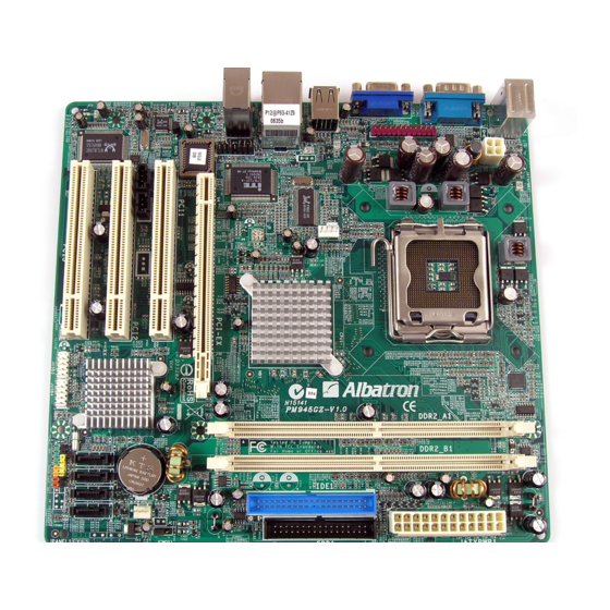
Page 9: Configuration
Mainboard PM945GZ Configuration Layout of PM945GZ... -
Page 10: Hardware Installation
Mainboard PM945GZ Hardware Installation This section will assist you in quickly installing your system hardware. Wear a wrist ground strap before handling components. Electrostatic discharge may damage the system’s components. CPU Processor Installation ® ® ® ® This mainboard supports Intel... -
Page 11: Memory Installation: Ddr2_A1/B1
Memory Installation: DDR2_A1/B1 The PM945GZ provides two DIMM (Dual In-Line Memory Modules) sockets which allowing you to install 240-pin, unbuffered non-ECC, DDRII 533/ 400 SDRAMs. It also supports Dual Channel Technology and allows you installing a total memory capacity of 2 GB. -
Page 12: Memory Installation Steps
Mainboard PM945GZ How to enable Dual-Channel DDRII: This mainboard provides Dual-Channel functionality for the two DIMM sockets. Enabling Dual-Channel can significantly increase your data access rates. DDR2_A1 and DDR2_B1 share one channel. For enabling Dual-Channel, you have to install two memories in the DIMM sockets at the same time;... -
Page 13: Back Panel Configuration
Mainboard PM945GZ Back Panel Configuration PS/2 Mouse & PS/2 Keyboard Ports: JKBMS1 This mainboard provides a standard PS/2 mouse port and a PS/2 keyboard port. The pin assignments are described below. PS/2 Mouse Assignment Assignment Data +5 V (fused) Clock... - Page 14 Mainboard PM945GZ USB Ports/LAN Port: JUSB2, JRJ45USB1 There are four onboard USB 2.0/ 1.1 ports on the back panel. These USB ports are used to attach with USB devices, such as keyboard, mice and other USB supported devices. There is also a 10/100 Mbps Ethernet LAN port available for you to attach an Internet cable.
-
Page 15: Connectors
Mainboard PM945GZ Connectors Floppy Disk Drive Connector: FDD1 The mainboard provides a standard floppy disk drive connector (FDD1) that supports 360KB/720KB/ 1.2MB/1.44MB/2.88 MB floppy disk drives using a FDD ribbon cable. Primary IDE Connector: IDE1 The mainboard provides one IDE connector that supports Ultra ATA 66/100 IDE devices. You can attach a maximum of two IDE devices, such as hard disk drive (HDD), CD-ROM, DVD-ROM, etc. -
Page 16: Front Panel Headers: Jpanel1
Mainboard PM945GZ Front Panel Headers: JPANEL1 JPANEL1 Assignment Function Assignment Function Sleep control Sleep button Speaker (SLP) Ground connector (SPK) Speaker Power LED (+) Power LED HDD LED (+) Power LED (+) Hard drive LED (HLED) HDD LED (-) Power LED (-) -
Page 17: Headers & Jumpers
Mainboard PM945GZ Power-on button Header ) : On/Off This header can be attached to a power switch cable on your case front panel. You can turn your system on or off by pressing the button attached to this power switch cable. - Page 18 Mainboard PM945GZ Printer Interface Header: JPRNT1 This mainboard provides a JPRNT1 header for you connecting an additional printer connector on your case back panel. Attach the cable of printer connector (Optional) onto this header, and then you can use the printer connector connecting with a printer.
-
Page 19: Audio Configuration
Mainboard PM945GZ Audio Configuration CD-ROM Audio-In Connector: JCDIN1 The CD-IN connector is used to attach an audio cable to audio devices such as CD-ROMs, DVD-ROMs etc. Assignment Left channel input Ground JCDIN1 Ground Right channel input SPDIF Header: JSPDIF_OUT1 S/PDIF is a recent audio transfer file format, which provides high quality audio using optical fiber and digital signals. -
Page 20: Slots
Mainboard PM945GZ Front Audio Header: JAUDIO2 If your case front panel has audio ports, you can connect them to the Front Audio Header of this mainboard. First, you must remove the jumper caps on this header and then attach the cables from the front panel to the pins on this header. -
Page 21: Power Supply Attachments
Mainboard PM945GZ Power Supply Attachments ATX Power Connector: JATXPWR1, JATXPWR2 This mainboard provides two ATX power connectors, a 24-pin JATXPWR1 connector and a 4-pin JATXPWR2 connector. You must use a power supply that has both of these connectors and both connectors must be attached before the system is powered on. -
Page 22: Chapter 2. Bios Setup
Mainboard PM945GZ Chapter 2. BIOS Setup Introduction This section describes PHOENIX-AWARD™ BIOS Setup program which resides in the BIOS firmware. The Setup program allows users to modify the basic system configuration. The configuration information is then saved to CMOS RAM where the data is sustained by battery after power-down. -
Page 23: Main Menu
Mainboard PM945GZ Main Menu Phoenix – AwardBIOS CMOS Setup Utility Standard CMOS Features Frequency/Voltage Control Advanced BIOS Features Load optimized Defaults Advanced Chipset Features Set Supervisor Password Integrated Peripherals Set User Password Power Management Setup Save & Exit Setup PnP/PCI Configurations... -
Page 24: Load Optimized Defaults
Mainboard PM945GZ Frequency/ Voltage Control It is for you to specify settings for Frequency and Voltage Control, such as the CPU’s clock and frequency ratio. Load Optimized Defaults It can load the preset system parameter values to set the system in its best performance configurations. -
Page 25: Chapter 3: Software Setup
Mainboard PM945GZ Chapter 3: Software Setup Software List Category Platform ® Windows 2000 /XP Intel Chipset INF ® Windows 2000 /XP Realtek Lan Driver ® Windows 2000 /XP Realtek Audio Driver ® Windows 2000 /XP Intel VGA Driver ® Windows 2000 /XP Microsoft DirectX9.0c... - Page 26 Mainboard PM945GZ Intel Chipset INF – It provides all drivers for the functions which built in both the Northbridge/ Southbridge. Realtek LAN Driver – It provides the driver of Realtek Network. Realtek Audio Driver – It provides the driver of Realtek AC’97 Audio CODEC.
- Page 27 Mainboard PM945GZ Adobe Acrobat Reader 6 – Installing the Adobe Acrobat Reader program, you can browse files with PDF styled. Trend PC-Cillin 2005 – It provides the software of Trend PC-Cillin 2005 (Anti-virus program). Drive Clone –It provides the software of Drive Clone which is used to back up or clone hard drives or partitions.
-
Page 28: Chapter 4: Troubleshooting
Mainboard PM945GZ Chapter 4: Troubleshooting Problem 1: No power to the system. Power light does not illuminate. Fan inside power supply does not turn on. Indicator lights on keyboard are not lit. Causes: 1. Power cable is unplugged. 2. Defective power cable. - Page 29 Mainboard PM945GZ Problem 4: System only boots from the CD-ROM. The hard disk can be read and applications can be used but booting from the hard disk is impossible. Causes: Hard Disk boot sector has been corrupted. Solutions: Back up data and applications files. Reformat the hard drive. Re-install applications and data using backup disks.
- Page 30 Mainboard PM945GZ Problem 10: Keyboard failure. Causes: Keyboard is disconnected. Solutions: Reconnect keyboard. Replace keyboard if you continue to experience problems. Problem 11: No color on screen. Causes: 1. Faulty Monitor. 2. CMOS incorrectly set up. Solutions: 1. If possible, connect monitor to another system. If no color appears, replace monitor.
-
Page 31: Appendix I: Super 5.1 Channel Audio Effect Setup
Mainboard PM945GZ Appendix I: Super 5.1 Channel Audio Effect Setup Channels Setup 1. After starting your system, click the Sound Effect Manager icon from the tool bar on the desktop. You can also find the icon by going to Start-> Setting -> Control Panel.
Need help?
Do you have a question about the PM945GZ and is the answer not in the manual?
Questions and answers