Table of Contents
Advertisement
Copyright
All rights are reserved. No part of this publication may be reproduced, transmitted, transcribed, stored
in a retrieval system or translated into any language or computer language, in any form or by any means,
electronic, mechanical, magnetic, optical, chemical, manual or otherwise, without the prior written
permission of the company. Brands and product names are trademarks or registered trademarks of their
respective companies.
The vendor makes no representations or warranties with respect to the contents herein and especially
disclaim any implied warranties of merchantability or fitness for any purpose. Further the vendor
reserves the right to revise this publication and to make changes to the contents herein without
obligation to notify any party beforehand. Duplication of this publication, in part or in whole, is not
allowed without first obtaining the vendor's approval in writing.
Trademark
All the trademarks or brands in this document are registered by their respective owner.
Disclaimer
We make no warranty of any kind with regard to the content of this user's manual. The content is
subject to change without notice and we will not be responsible for any mistakes found in this user's
manual. All the brand and product names are trademarks of their respective companies.
FCC Compliance Statement
This equipment has been tested and found to comply with the limits of a Class B digital device, pursuant
to Part 15 of the FCC Rules. These limits are designed to provide reasonable protection against harmful
interference in a residential installation. This equipment generates, uses and can radiate radio
frequency energy and, if not installed and used in accordance with the instructions, may cause harmful
interference to radio communications. Operation of this equipment in a residential area is likely to
cause harmful interference in which case the user will be required to correct the interference at his own
expense. However, there is no guarantee that interference will not occur in a particular installation.
CE Mark
The device is in accordance with 89/336 ECC-ENC Directive.
Ver: EG101
Intel
PX915P-2V
PX915P-2V
Intel
915P & ICH6
®
Support Socket 775
Pentium
4 Prescott Processor
®
®
Advertisement
Table of Contents

Subscribe to Our Youtube Channel
Related Manuals for Albatron PX915P-2V


Summary of Contents for Albatron PX915P-2V
-
Page 1: Fcc Compliance Statement
PX915P-2V Copyright All rights are reserved. No part of this publication may be reproduced, transmitted, transcribed, stored in a retrieval system or translated into any language or computer language, in any form or by any means, electronic, mechanical, magnetic, optical, chemical, manual or otherwise, without the prior written permission of the company. -
Page 2: Operating System
User Manual Enabling the Hyper-Threading Technology, your computer system is required to have components as the following: CPU: An Intel ® Pentium ® 4 Processor with HT Technology Chipset: An Intel Chipset that supports HT Technology ® BIOS: A BIOS that supports HT Technology must be enabled OS: An operating system that supports HT Technology For more information on Hyper-Threading Technology, go to: http://www.intel.com/info/hyperthreading... - Page 3 Do not touch any IC chip, lead, connector or other components. Always unplug the AC power when you install or remove any device on the mainboard or when confuguring pins and switches. Packing List PX915P-2V Mainboard IDE Cable FDD Cable SATA Cable...
-
Page 4: Table Of Contents
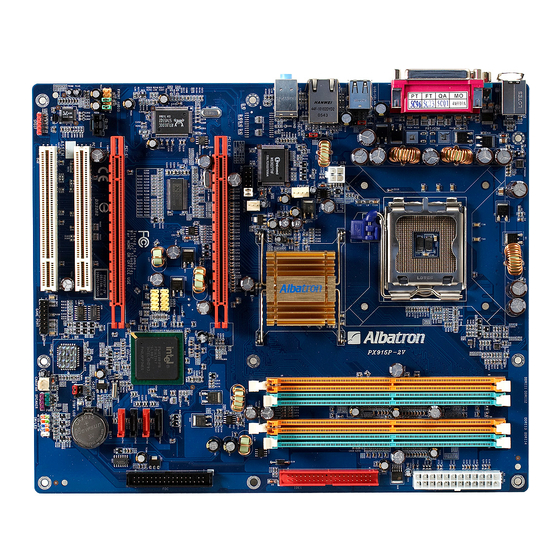
Layout of PX915P-2V ..................4 ................... 5 ARDWARE NSTALLATION CPU Processor Installation................6 Memory Installation ..................7 Back Panel Configuration................8 Connectors..................... 10 Front Panel Headers..................11 Headers & Jumpers..................12 Audio Configuration..................15 Slots ....................... 16 Power Supply Attachments................16 CHAPTER 2. -
Page 5: Chapter 1. Getting Started
There are maximal eight USB2.0/ 1.1 ports can be set on this mainboard. The PX915P-2V also comes with an onboard 10/100 Mbps Ethernet LAN chip (1GBLAN is optional). There is a LAN port on the case back panel that you can directly plug into an Internet cable. -
Page 6: Fdd Connector
Mainboard PX915P-2V Chipset: Northbridge Chipset – Intel® 915P Southbridge Chipset – Intel® ICH6 I/O Controller – Winbond® W83627THF AC’ 97 Sound Codec – Realtek® ALC655 Mb LAN Controller – Realtek® RTL 8100C Gb LAN Controller – Realtek® RTL 8110S (Optional) -
Page 7: Usb Ports
Mainboard PX915P-2V Supports SATA 1.0 specification and with 150MBps transmission speeds Onboard AC’ 97 Sound Codec: High performance Codec with high S/N ratio (>90 db) Compliant with AC’ 97 2.3 specification Supports 6 channel playback capability (Super 5.1 Channel Audio Effect) -
Page 8: C Onfiguration
This function is used for detecting the system hangs during the POST stage due to conflicts resulting from changing the system BIOS settings. Once the problem is detected, the system will reset the configurations and reboot the system within five seconds. ABS (Albatron BIOS Security): Supports ABS card (optional) Supports BIOS backup... -
Page 9: Hardware Installation
Mainboard PX915P-2V Hardware Installation This section will assist you in quickly installing your system hardware. Wear a wrist ground strap before handling components. Electrostatic discharge may damage the system’s components. -
Page 10: Cpu Processor Installation
Mainboard PX915P-2V CPU Processor Installation ® ® This mainboard supports Intel Pentium 4 Prescott Processors using a Socket 775. Before building your system, we suggest you to visit the Intel website and review the processor installation procedures. http://www.intel.com CPU Socket 775 Configuration Steps: 1. -
Page 11: Memory Installation
Memory Installation: DIMM1/2 The PX915P-2V provides four DIMM (Dual In-Line Memory Modules) sockets which allowing you to install 240-pin, unbuffered non-ECC, DDRII 400/ DDRII 533 SDRAMs. It also supports Dual Channel Technology and allows you installing a total memory capacity of 4 GB. -
Page 12: Back Panel Configuration
Mainboard PX915P-2V 2. Match the notch on the RAM module with the corresponding pattern in the DIMM slot. This will ensure that t he module will be inserted with the proper orientation. Lower the RAM module into the DIMM Slot and press firmly using bo th thumbs until the module snaps into place. - Page 13 Mainboard PX915P-2V PS/2 Mouse & PS/2 Keyboard Ports: KB/MS This mainboard provides a standard PS/2 mouse port and a PS/2 keyboard port. The pin assignments are described below. PS/2 Mouse Assignment Assignment Data +5 V (fused) No connect Clock Ground...
-
Page 14: Connectors
Mainboard PX915P-2V Audio Ports: Sound his mainboard provides three audio ports, the Mic-in Line-in and Line-out hese are the standard audio ports that provide ic au dio function. Line -In (Blue) his port is for audio input and connects to exte... -
Page 15: Front Panel Headers
Mainboard PX915P-2V Attention The FDD/IDE cab e is designed and shou ld be attached with a specific direction. One edge of the cable will usually in color such as red, to indicate that should line up with the header pin-1. -
Page 16: Headers & Jumpers
Mainboard PX915P-2V owe Switch Head (Ora nge): PW R_SW s he r can be attached a power switch cab le o our c ase front panel. Y ou can turn yo ur sys or off y pressing the bu n attached to this p... - Page 17 Mainboard PX915P-2V Assignment Assignment J1B1 J2B1 J1CX J2CX Ground MIDI_OUT GAME PORT Ground J2CY J1CY J2B2 J1B2 MIDI_IN Case Open Warning Header: CASE OPEN his header is used to warn th e use hen th e compute r case h...
- Page 18 Mainboard PX915P-2V USB Power Selection Headers: JP3/JP4 SB devices attached to the back pane l USB ports can awaken the system from sleep mode. In order to nable this functio nality, you must adjust the jumper caps on JP3/JP4 header for +5V or +5V Stand ode depending o n which port of the compatible device is attached to.
-
Page 19: Audio Configuration
Mainboard PX915P-2V Audio Con figuration CD-ROM A udio-In Connector: CD-IN he CD-IN connecto r is used to attach an audio ca ble to audio devices such as CD-ROMs, DVD-ROMs etc. Assignment Left channel input Ground CD-IN Ground Right channel input... -
Page 20: Slots
Mainboard PX915P-2V Front Audio Header: FRONT AUDIO your case front panel has audio ports, you can connect them to the Front Audio Header of this ainboard. First, you must remove the jumper caps on this header and then attach the cables from the ont panel to the pins on this header. -
Page 21: Chapter 2. Bios Setup
Mainboard PX915P-2V Ground Ground P W_ON +5V st andby v oltage +12V +12V +3.3V Ground ignm signmen +12V Ground +12V Ground ATX_12V Atte ntio In gen l, po wer cords are designed and should be attached with a specific directio n. -
Page 22: Key Function
Mainboard PX915P-2V APM Support his PHOENIX-AWARD™ BIOS supports th e Version 1.1 & 1.2 of Advanced Power Management (APM) specification. These features include system sleep and suspend modes in addition to h ard disk and onitor sleep modes. Power management features are implemented using the System Management Interrupt (SMI). -
Page 23: Main Menu
Mainboard PX915P-2V Keystroke Function Up arrow Move to previous option Down arrow Move to next option Left arrow Move to the option on the left (menu bar) Right arrow Move to the option on the right (menu bar) Main Menu: Quit without saving changes... -
Page 24: Advanced Bios Features
Mainboard PX915P-2V Option Options Description Set the system d ate. Note that the ‘Day’ Date mm dd yyyy automatically c hanges when you set the date. Time Hh: mm: ss Set the current time of the system. IDE Cha nnel 0... - Page 25 Mainboard PX915P-2V Removable Device Priority Select removable device boot priority. Hard Disk Boot Priority Select hard disk boot priority. First /Second/Third Boot Device Select the order in which devices will be searched in or der to find a boot device.
-
Page 26: Virus Warning
Mainboard PX915P-2V Virus Warning This option allows you t o choose the Virus Warning feature for IDE Hard Disk boot sector protection. If this function is enabled and someone attempts to write data into this area, BIOS will display a warning message on the screen and sound an audio alarm (beep). -
Page 27: Advanced Chipset Features
Mainboard PX915P-2V PS Version Control For OS The 1.1 version is the older version that supports 8 more IRQs in the Windows NT environment. Choose the new 1.4 version for Windows 2000 and Windows XP. Options: 1.4 (Default), 1.1 S Select For DRAM > 64MB Select “OS2”... - Page 28 Mainboard PX915P-2V RAM RAS# Precharge This option allows you to select the DRAM RAS# precharged time. The ROW address strobe must be precharged again before DRAM is refreshed. An inadequate configuration may result in incomplete data. This option is adjustable only when “DRAM Timing Selectable” is set to “manual”. This option is locked when “DRAM Timing Selectable”...
-
Page 29: Maximum Payload Size
Mainboard PX915P-2V CI SLOT1/2 This option allows you to select an IRQ address for PCI slot 1/2. Options: Auto (Default),3,4,5,7,9,10,11,12,14,15 PCI Express relative Items** Maximum payload Size This option allows you to set the PCI Express Maximum payload size per time. -
Page 30: Onchip Ide Device
Mainboard PX915P-2V DR Voltage (Volt) This option allows you to adjust the RAM voltage. Options: Default (Default),+0.05,+0.10,+0.15 B Voltage (Volt) This option allows you to adjust the North Bridge voltage. Options: Default (Default),+0.05,+0.10,+0.15 efault CPU Voltage (Volt) This option displays the CPU default Voltage. -
Page 31: Onchip Serial Ata Setting
Mainboard PX915P-2V second IDE interface. Select “Disabled” to deactivate the interface if you are going to install a primary and/or secondary add-in IDE interface. Options: Enabled (Default),Disabled E channel0/ channel1/Master/Slave PIO The IDE PIO (Programmed Input / Output) options let you set a PIO mode (0-4) for each of the IDE devices that the onboard IDE interface supports. -
Page 32: Onboard Device
Mainboard PX915P-2V ATA Port This option will display which IDE channel will be used to the SATA device. Options: SATA2, 4 is channel Onboard Device SB Controller This option should be enabled if your system has a USB port installed on the system board. You will need to disable this feature if you add a higher performance controller. - Page 33 Mainboard PX915P-2V nboard FDC Controller Select “Enabled” if your system has a floppy disk controller (FDC) installed on the system board and you wish to use it. If you install an add-in FDC or the system has no floppy drive, select “Disabled”. Options:...
-
Page 34: Power Management
Mainboard PX915P-2V PP Mode Select Select EPP port type 1.7 or 1.9. This option is configurable only if “Parallel Port Mode” is set to “EPP” or “ECP+EPP”. Options: EPP 1.9 (Default),EPP 1.7 CP Mode Use DMA Select a DMA Channel for the parallel port when using the ECP mode. This option is configurable only if “Parallel Port Mode”... -
Page 35: Acpi Suspend Type
Mainboard PX915P-2V ACPI Suspend Type The option allows you to select the suspend type using the ACPI operating system. Options: S1 (POS) (Default) Power on Suspend S3 (STR) Suspend to RAM S1 & S3 POS and STR Run VGABIOS if S3 Resume Select whether you want to run VGABIOS when the system wakes up from the S3 suspend function. -
Page 36: Modem Use Irq
Mainboard PX915P-2V Options: Stop Grant (Default),PwrOn Suspend Modem Use IRQ This determines the modem’s IRQ. Options: 3 (Default),4,5,7,9,10,11,NA. Suspend Mode This option allows you to select the suspend time under the ACPI operating system. Options: Disabled(Default),1Min,2Min,4Min,8Min,12Min,20Min,30Min,40Min,1Hour HDD Power Down When enabled, the hard disk drive will power down after a certain configurable period of system inactivity. -
Page 37: Hardware Monitor
Mainboard PX915P-2V ate (of Month) Alarm You can choose which date of the month the system will boot up. This option is configurable only when “RTC Wake Up” is set to “Enabled”. ime (hh: mm: ss) Alarm You can choose the hour, minute and second the system will boot up. This option is configurable only when “RTC Wake Up”... -
Page 38: Defaults
Mainboard PX915P-2V Options: Disabled (default),30 C / 86 F,35 C / 95 F,40 C / 104 F,45 C / 113 F,50 C / 122 F,55 F,60 C / 140 F,65 C / 149 F,70 C / 158 F,75 C / 167... -
Page 39: Chapter 3: Software Setup
Mainboard PX915P-2V Save & Exit Setup Save all configuration changes to CMOS (memory) and exit setup. A confirmation message will be displayed before proceeding. Exit Without Saving Abandon all changes made during the current session and exit setup. A confirmation message will be displayed before proceeding. - Page 40 Mainboard PX915P-2V several buttons displayed in the main screen as shown below. Intel Chipset INF – It provides all drivers for the functions which built in both the Northbridge/ Southbridge Realtek AC’97 Audio Driver – It provides the driver of Realtek AC’97 Audio Codec Note:You can only install this driver if you are using Windows®...
-
Page 41: Chapter 4: Troubleshooting
Mainboard PX915P-2V Trend PC-Cillin 2005 – It provides the software of Trend PC-Cillin 2005 (Anti-virus program) Microsoft DirectX9.0c – It provides the software of Microsoft DirectX9.0c Adobe Acrobat Reader 6 – Installing the Adobe Acrobat Reader program, you can browse files with pdf styled Dr. - Page 42 Mainboard PX915P-2V Solutions: 1. Check the cable running from the disk to the disk controller board. Make sure both ends are securely attached. Check the drive type in the standard CMOS setup. 2. Contact technical support. 3. Backing up the hard drive is extremely important. Make sure your periodically perform backups to avoid untimely disk crashes.
- Page 43 Mainboard PX915P-2V Problem 9: Screen goes blank periodically. Causes: Screen saver is enabled. Solutions: Disable screen saver. Problem 10: Keyboard failure. Causes: Keyboard is disconnected. Solutions: Reconnect keyboard. Replace keyboard if you continue to experience problems. Problem 11: No color on screen.
-
Page 44: Appendix I: Super 5.1 Channel Audio Effect Setup
Mainboard PX915P-2V Problem 15: Certain keys do not function. Causes: Keys jammed or defective. Solutions: Replace keyboard. Appendix I: Super 5.1 Channel Audio Effect Setup Channels Setup 1. After starting your system, click the Sound Effect Manager icon from the tool bar on the desktop. -
Page 45: Appendix Ii: Abs (Albatron Bios Security) Card Setup
Appendix II: ABS (Albatron BIOS Security) Card Setup Introduction The ABS (Albatron BIOS Security) system provides your system with a recovery BIOS backup when your onboard BIOS has been damaged beyond system boot capability. Preparation and Setup You should prepare a boot floppy disk and have it ready in case of such BIOS failures. Otherwise you will have to find another computer to make the boot floppy disk from. - Page 46 Mainboard PX915P-2V will display a message that will give you an opportunity to enter the BIOS setup utility (typically, “Press Delete Key to enter BIOS utility”) . Once in the BIOS Utility, follow this path: Advanced -> Hard Disk Boot Priority -> First Boot Device and set the “First Boot Device”...
- Page 47 Mainboard PX915P-2V The next screen (shown above-right) will display a message “Press ’Y’ to Program or ‘N’ to Exit”. Then type ‘Y’ to begin the onboard BIOS flash procedure. 9. The flashing procedure will take several minutes and will show its progress on the screen. After the flash BIOS procedures have completed, press ‘F1’...
- Page 48 Mainboard PX915P-2V Follow the path: Defaults -> Load System Default Settings -> Y . Next, follow the path: Exit -> Save & Exit Setup -> Y Follow the path: Exit -> Save & Exit Setup -> Y . 11. After you have recovered your onboard BIOS, you can choose to remove or not remove the ABS Card from the mainboard.
- Page 49 Mainboard PX915P-2V If you choose not remove the ABS Card from the mainboard, make sure that the jumper caps on the ABS_JP1 header located on the ABS Card to the “Onboard BIOS” as below, in order to reduce the damage opportunity of the rescue BIOS in ABS Card and on the other hand to extend the usage life of the ABS Card.
Need help?
Do you have a question about the PX915P-2V and is the answer not in the manual?
Questions and answers