Table of Contents
Advertisement
Quick Links
PX915P/ PX915G Series
Copyright
All rights are reserved. No part of this publication may be reproduced, transmitted,
transcribed, stored in a retrieval system or translated into any language or computer
language, in any form or by any means, electronic, mechanical, magnetic, optical,
chemical, manual or otherwise, without the prior written permission of the company.
Brands and product names are trademarks or registered trademarks of their respective
companies.
The vendor makes no representations or warranties with respect to the contents herein
and especially disclaim any implied warranties of merchantability or fitness for any
purpose. Further the vendor reserves the right to revise this publication and to make
changes to the contents herein without obligation to notify any party beforehand.
Duplication of this publication, in part or in whole, is not allowed without first obtaining
the vendor's approval in writing.
Trademark
All the trademarks or brands in this document are registered by their respective owner.
Disclaimer
We make no warranty of any kind with regard to the content of this user's manual. The
content is subject to change without notice and we will not be responsible for any
mistakes found in this user's manual. All the brand and product names are trademarks of
their respective companies.
FCC Compliance Statement
This equipment has been tested and found to comply with the limits of a Class B digital
device, pursuant to Part 15 of the FCC Rules. These limits are designed to provide
reasonable protection against harmful interference in a residential installation. This
equipment generates, uses and can radiate radio frequency energy and, if not installed
and used in accordance with the instructions, may cause harmful interference to radio
communications. Operation of this equipment in a residential area is likely to cause
harmful interference in which case the user will be required to correct the interference
at his own expense. However, there is no guarantee that interference will not occur in a
particular installation.
CE Mark
The device is in accordance with 89/336 ECC-ENC Directive.
120410091M1N
Advertisement
Table of Contents

Related Manuals for Albatron PX915P Series


Summary of Contents for Albatron PX915P Series
- Page 1 PX915P/ PX915G Series Copyright All rights are reserved. No part of this publication may be reproduced, transmitted, transcribed, stored in a retrieval system or translated into any language or computer language, in any form or by any means, electronic, mechanical, magnetic, optical, chemical, manual or otherwise, without the prior written permission of the company.
- Page 2 Important, please read!!! The images and pictures in this manual are for reference only and may vary slightly from actual product installation depending on specific hardware models, third party components and software versions. Unplug your computer when installing components configuring switches and pins. This mainboard contains very delicate IC chips.
- Page 3 PX915P/ PX915G Series ® Intel 915P/ 915G & ICH6 ® ® Supports Socket 775 Intel Pentium Prescott Processor User Manual Enabling Hyper-Threading for your computer system requires ALL of the following components CPU: An Intel ® Pentium ® 4 Processor with HT Technology Chipset: An Intel ®...
-
Page 4: Table Of Contents
Contents CHAPTER 1. GETTING STARTED .............1 ......................1 NTRODUCTION ......................2 PECIFICATION ....................... 5 ONFIGURATION Layout of PX915P PRO..................5 Layout of PX915P ....................6 Layout of PX915G PRO..................7 Layout of PX915G....................8 ..................9 ARDWARE NSTALLATION CPU Processor Installation ................... 9 Back Panel Configuration................... -
Page 5: Chapter 1. Getting Started
These mainboards support up to 8 USB2.0 ports and also provide an infrared header for wireless infrared transmissions. The PX915P series and the PX915G series mainboards come with a LAN chip (Marvell ® MV8001) that provides up to 1 GB/s network connectivity. The PX915P PRO and PX915G PRO also come with a secondary LAN chip (VIA VT6105 LAN controller) which provides an additional back panel LAN port capable of 10/100 Mbit/s transmission speeds. -
Page 6: Specification
4 Prescott processor Supports Hyper-Threading Technology 533/ 800 MHz FSB (Front Side Bus) frequencies Chipset: Northbridge Chipset – Intel® 915P (PX915P Series)/ 915G (PX915G Series) Southbridge Chipset – Intel® ICH6 I/O Controller – Winbond W83627THF RAID IDE Controller – ITE IT8212F HD Aduio Codec –... - Page 7 PX915P/ PX915G Series Onboard IDE Facilities: Supports Ultra ATA 66/ 100, DMA and PIO modes Supports IDE interface with CD-ROM Supports high capacity hard disk drives IDE slot can support 2 IDE drives Raid IDE controller: Two RAID IDE slots that supports Ultra ATA 133 IDE Supports hard disk drives only Each slot can support 2 IDE drives Supports RAID 0, RAID 1, RAID 0+1 and JBOD modes...
- Page 8 PX915P/ PX915G Series Onboard Video Graphic: (only for PX915G series) Supports 2D Acceleration Supports 3D Acceleration Supports Video Acceleration Micorsoft ® DirectX compatible OpenGL driver available I/O facilities: multi-mode Parallel Port capable supporting following specifications: 1. Standard & Bi-direction Parallel Port 2.
-
Page 9: Configuration
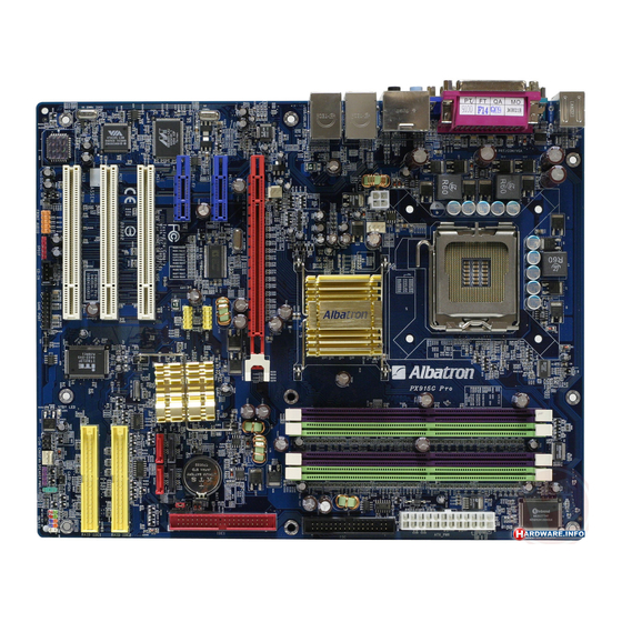
PX915P/ PX915G Series Configuration Layout of PX915P PRO... -
Page 10: Layout Of Px915P
PX915P/ PX915G Series Layout of PX915P... -
Page 11: Layout Of Px915G Pro
PX915P/ PX915G Series Layout of PX915G PRO... -
Page 12: Layout Of Px915G
PX915P/ PX915G Series Layout of PX915G... -
Page 13: Hardware Installation
PX915P/ PX915G Series Hardware Installation This section will assist you in quickly installing your system hardware. Wear a wrist ground strap before handling components. Electrostatic discharge may damage the system’s components. CPU Processor Installation This mainboard supports Intel Pentium 4 processors using a Socket 775. Before building ®... - Page 14 PX915P/ PX915G Series FAN Headers Three power headers are available for the cooling fans. Cooling fans play an important role in maintaining the ambient temperature in your system. Attention: We strongly recommend that you use a CPU fan sink with your CPU. You can attach the power cable from the CPU fan sink to the CPUFAN Header.
- Page 15 PX915P/ PX915G Series How to enable Dual-Channel DDR : These mainboards provide Dual-Channel functionality for its DIMM slots. Enabling Dual-Channel can significantly increase your data access rates. DIMM1 and DIMM2 share one channel, while DIMM3 and DIMM4 share the second channel. Enabling Dual-Channel simply means to make sure that the total memory for the two channels are balanced.
-
Page 16: Back Panel Configuration
PX915P/ PX915G Series Back Panel Configuration PS/2 Mouse & PS/2 Keyboard Connectors: KB/MS These mainboards provide a standard PS/2 mouse connector and PS/2 keyboard connector. The pin assignments are described below: PS/2 Mouse Assignment Assignment Data +5 V (fused) No connect Clock Ground No connect... - Page 17 PX915P/ PX915G Series USB & (GB) LAN Connectors: USB/ GB LAN and (USB/ LAN is only for PX915P PRO and PX915G PRO) These mainboards come with 4 USB ports and a Gb/s LAN port. The PX915P Pro and PX915G Pro have an additional 10/100 Mbit/s LAN port. The USB connectors are used to attach to keyboards, mice and other USB devices.
-
Page 18: Connectors
PX915P/ PX915G Series Connectors Floppy Disk Connector: FDC These mainboards provide a standard floppy disk connector (FDC) that supports 360K, 720K, 1.2M, 1.44M and 2.88M floppy diskette drives. This connector supports the floppy drive ribbon cables provided in the packaging. Hard Disk Connectors: IDE1/ RAID IDE1-2/ SATA1-4 These mainboards provide a standard IDE connector that supports PIO Mode 0~4, Bus Master, Ultra ATA 66/100. -
Page 19: Front Panel Indicator: Sw/Led、Pwrled、Speaker
PX915P/ PX915G Series Front Panel Indicator: SW/LED、PWRLED、SPEAKER HD LED (Hard Drive LED Connector/ red) This connector can be attached to an LED on the front panel of a computer case. The LED will flicker during any disk activity. RST SW (Reset Connector/ blue) This connector can be attached to a momentary SPST switch. -
Page 20: Headers & Jumpers
PX915P/ PX915G Series Headers & Jumpers Infrared Header: IrDA You can attach an infrared device to this connector and use this connector for connectionless infrared data transfers. Game Port Header: GAME PORT There is a game port header on these mainboards. To use this header, you must attach a game port bracket-cable so that you can interface to gaming devices (game port bracket is optional). - Page 21 PX915P/ PX915G Series Clear CMOS Jumper: JP1 The “Clear CMOS” jumper allows you to reset your CMOS configurations. This is particularly useful when you have forgotten your system password and cannot boot to the operating system. The following steps explain how to reset your CMOS configurations when you have forgotten your system password.
-
Page 22: Audio Connectors
PX915P/ PX915G Series Audio Connectors CD-ROM Audio-In Header: CD-IN This header is used to connect to the CD-ROM/DVD audio cable Front Panel Audio Header (Orange): FRONT AUDIO You can use the Front Panel Audio header (FRONT AUDIO) to connect to a separate audio bracket or to connect to case embedded audio equipment. - Page 23 PX915P/ PX915G Series S/PDIF Header (Red): SPDIF S/PDIF (Sony/Philips Digital Interface) is an audio transfer file format which provides high quality audio using optical fiber and digital signals. This mainboard is equipped with an SPDIF header and must be used with a bracket-cable containing S/PDIF ports. An SPDIF/Audio bracket is optionally packaged with some models.
-
Page 24: Slots
PX915P/ PX915G Series Slots There is one PCI-Express x16 slot, 2 PCI-Express x1 slots and 3 PCI slots. These slots are designed for expansion cards to complement and enhance the functionality of the mainboard. PCI-Express slots: PCI-E X16 & PCI-E1/ PCI-E2 PCI-E x16 slots are for installing PCI-Express graphics cards. -
Page 25: Chapter 2. Bios Setup
PX915P/ PX915G Series Chapter 2. BIOS Setup Introduction This section describes PHOENIX-AWARD™ BIOS Setup program which resides in the BIOS firmware. The Setup program allows users to modify the basic system configuration. The configuration information is then saved to CMOS RAM where the data is sustained by battery after power-down. - Page 26 PX915P/ PX915G Series Supported CPUs This PHOENIX-AWARD™ BIOS supports the Intel Pentium 4 CPUs. ® ® Key Function In general, you can use the arrow keys to highlight items, press <Enter> to select, use the <PgUp> and <PgDn> keys to change entries, press <F1> for help and press <Esc> to quit.
-
Page 27: Main Menu
PX915P/ PX915G Series Main Menu When you enter the PHOENIX-AWARD™ BIOS Utility, the Main Menu will appear on the screen. The Main menu allows you to select from several configuration options. Use the left/right arrow keys to select a particular configuration screen from the top menu bar or use the down arrow key to access and configure the information below. - Page 28 PX915P/ PX915G Series Main Menu Setup Configuration Options Item Options Description Set the system date. Note that the ‘Day’ automatically Date mm dd yyyy changes when you set the date. Time Hh: mm: ss Set the current time of the system. IDE Channel 0/1 Options contained in Press <Enter>...
-
Page 29: Advanced Bios Features
PX915P/ PX915G Series Advanced BIOS Features Removable Device Priority Select removable device priority. Just like floppy, LS120, ZIP-100, USB-FDD and USB-ZIP. Hard Disk Boot Priority Select hard disk boot priority. CD-ROM Boot Priority Select CD-ROM boot priority. First /Second/Third Boot Device Select the order in which devices will be searched in order to find a boot device. - Page 30 PX915P/ PX915G Series Advanced BIOS Features CPU Feature Delay Prior Select the delay time before thermal activation from high temperatures. Options: 4 Min、8 Min、16 Min (default)、32 Min Thermal Management This item will monitor the CPU thermal to prevent the CPU damage with high temperature.
- Page 31 PX915P/ PX915G Series Typematic Rate Setting When “Enabled”, the “typematic rate” and “typematic delay” can be configured. Typematic Rate determines the keystroke repeat rate used by the keyboard controller.. Options: Disabled (default)、Enabled Typematic Rate (Chars/Sec) The rate at which a character repeats when you hold down a key. Options: 6 (default)、8、10、12、15、20、24、30 Typematic Delay (Msec) The delay before keystrokes begin to repeat.
- Page 32 PX915P/ PX915G Series CAS Latency Time This item determines CAS Latency. When synchronous DRAM is installed, the number of clock cycles of CAS latency depends on the DRAM timing. Do not reset this field from the default value specified by the system engineer. This field is adjustable only when “DRAM Timing Selectable”...
- Page 33 PX915P/ PX915G Series PCI Express Root Port Func PCI Express Port1/2 This item allows you to enabled or disabled PCI Express x 1 port 1/ 2. Options: Auto (default)、Disabled PCI-E Compliancy Mode This item allows you select the PCI-E Compliancy Mode. Options: V1.0a (default)、V1.0 **VGA Setting** (only for onboard VGA) PEG Force X1 This item allows you to force the PCI-Express x 16 slot to install the PCI-Express x 1...
- Page 34 PX915P/ PX915G Series Resources Controlled By BIOS can automatically configure all the boot and Plug and Play compatible devices. If you choose Auto, you will not be able to manually assign IRQ DMA and memory base address fields, since BIOS automatically assigns them. Options: Auto (ESCD) (default)、 Manual IRQ Resources When resources are controlled manually, you can assign each system interrupt a type,...
- Page 35 PX915P/ PX915G Series PCI-E Speed Setting This item determines the PCI-E frequencY (speed settings). You can set the frequency using the supplied BIOS options. One of the options available to you is “Auto”. Using the “Auto” option will instruct the system to automatically calculate the frequency. Options: Auto (default)、100 System Memory Frequency This item allows you to select Memory Frequency.
-
Page 36: Integrated Peripherals
PX915P/ PX915G Series Integrated Peripherals Init Display First With systems that have multiple video cards, this option determines whether the primary display uses a PCI slot or an AGP slot. Options: PCIEx (default)、PCI Slot OnChip IDE Device IDE HDD Block Mode Block mode is otherwise known as block transfer, multiple commands, or multiple sector read/write. - Page 37 PX915P/ PX915G Series IDE channel0 /channel1 /Master / Slave UDMA Ultra DMA 100 functionality can be implemented if it is supported by the IDE hard drives in your system. As well, your operating environment requires a DMA driver (Windows 95 OSR2 or a third party IDE bus master driver).
- Page 38 PX915P/ PX915G Series Onboard Device USB Controller This option should be enabled if your system has a USB port installed on the system board. You will need to disable this feature if you add a higher performance controller. Options: Enabled (default)、Disabled USB 2.0 Controller This option should be enabled if your system has a USB 2.0 device installed on the system board.
- Page 39 PX915P/ PX915G Series Hot Key Power ON This option allows you to use the Ctrl key along with a hot key (function key) to power on your system. This field is only configurable when “Power On Function” is set to “Hot Key”. Options: Ctrl-F1、Ctrl-F2……...
- Page 40 PX915P/ PX915G Series Parallel Port Mode This option allows you to select a parallel port mode for the onboard parallel port. Options: ECP (default) Extended Capabilities Port. Enhanced Parallel Port. Standard Printer Port. ECP+EPP ECP & EPP mode. Normal EPP Mode Select Select EPP port type 1.7 or 1.9.
-
Page 41: Power Management
PX915P/ PX915G Series Power Management The Power Management Setup Menu allows you to configure your system to utilize energy conservation features as well as power-up/ power-down options. ACPI Suspend Type The item allows you to select the suspend type using the ACPI operating system. Options: S1 (POS) (default) Power on Suspend... - Page 42 PX915P/ PX915G Series 3. User Defined (default) Allows you to set each mode individually. When this option is enabled, each of the ranges are from 1 minute to 1 hour except for HDD Power Down, which ranges from 1 minute to 15 minute and includes a “disable” option.
- Page 43 PX915P/ PX915G Series Soft-Off by PWRBTN In situations where the system enters a “hung” state, you can configure the BIOS so that you are required to pre the power button for more than 4 seconds before the system enters the Soft-Off state. Options: Delay 4 Sec, Instant-Off (default).
-
Page 44: Hardware Monitor
PX915P/ PX915G Series Hardware Monitor Case Open Warning If this function is set to “Enabled” and the case had been previously opened, the system will automatically display alert messages on the screen when you power on your computer. If this function is set to “Disabled”, the system will not show alert messages when you power on your computer even if the case had been previously opened. -
Page 45: Load Defaults
PX915P/ PX915G Series Load Defaults Load System Default Settings Load System Default Settings. Load System Turbo Settings Load System Turbo Settings. Load CMOS From BIOS Load defaults from flash ROM for systems without batteries. Save CMOS To BIOS Save defaults to flash ROM for systems without batteries. -
Page 46: Exit Menu
PX915P/ PX915G Series Exit Menu Save & Exit Setup Save all configuration changes to CMOS (memory) and exit setup. A confirmation message will be displayed before proceeding. Exit Without Saving Abandon all changes made during the current session and exit setup. A confirmation message will be displayed before proceeding. -
Page 47: Chapter 3: Software Setup
PX915P/ PX915G Series Chapter 3: Software Setup Software List Category Platform Intel Chipset INF Windows 98 /ME /2000 /XP Realtek Audio Driver Windows 2000 /XP Intel onboard VGA Driver (only for PX915G series) Windows 2000 /XP ITE RAID Windows 2000 /XP VIA Network Driver (Only for PX915P/G PRO) Windows 98 /ME /2000 /XP Marvell Network Driver... - Page 48 PX915P/ PX915G Series Intel Chipset INF – provides all the drivers of the functions that built in the Northbridge/ Southbridge Realtek Audio Driver – provides the driver of Realtek HD Audio Codec Note:You can only install this driver if you are using Windows®...
- Page 49 PX915P/ PX915G Series How to install Windows® 98/ ME to the SATA device? 1. Make sure that the “On-Chip Serial ATA” option is set to “ Combined Mode” in the BIOS Setup Utility. (For more details, please see page 33 “OnChip Serial ATA Setting”.) BIOS Setup Utility ->...
-
Page 50: Chapter 4: Troubleshooting
PX915P/ PX915G Series Chapter 4: Troubleshooting Problem 1: No power to the system. Power light does not illuminate. Fan inside power supply does not turn on. Indicator lights on keyboard are not lit. Causes: 1. Power cable is unplugged. 2. Defective power cable. 3. - Page 51 PX915P/ PX915G Series Problem 4: System only boots from the CD-ROM. The hard disk can be read and applications can be used but booting from the hard disk is impossible. Causes: Hard Disk boot sector has been corrupted. Solutions: Back up data and applications files. Reformat the hard drive. Re-install applications and data using backup disks.
- Page 52 PX915P/ PX915G Series Problem 10: Keyboard failure. Causes: Keyboard is disconnected. Solutions: Reconnect keyboard. Replace keyboard if you continue to experience problems. Problem 11: No color on screen. Causes: 1. Faulty Monitor. 2. CMOS incorrectly set up. Solutions: 1. If possible, connect monitor to another system. If no color appears, replace monitor. 2.
-
Page 53: Appendix I: 2/ 4/ 6 /8 Channel Setup
PX915P/ PX915G Series Appendix I: 2/ 4/ 6 /8 Channel Setup 1. After into the system, click the audio icon from the Windows screen. 2. Click Speaker Configuration button, you can see the screen like the picture below. 3. You can choice 2, 4, 6 or 8 channels by your speakers. 4. -
Page 54: Ii: Intel ® Desktop Processors Feature Set Reference Table
PX915P/ PX915G Series Appendix II: Intel® Desktop Processors Feature Set Reference Table Intel Pentium ® 4 Processors reference table: Processor Front Processor Clock Intel Generation/ Side Cache Number Speed Technologies Socket 7XX Sequence Prescott/LGA775 3.73 GHz 1066 MHz 2MB L2 5XX Sequence Prescott/LGA775 4.00 GHz...
Need help?
Do you have a question about the PX915P Series and is the answer not in the manual?
Questions and answers