Table of Contents
Advertisement
Quick Links
USER'S MANUAL Of
Intel H55 Express Chipset
Based
M/B for Intel LGA 1156 Processors
PMH55
MB Rev.: 1.0
Manual Rev.: EG100
Release date: January, 2010
Trademark:
* Specifications and Information contained in this documentation are furnished for information use only, and are
subject to change at any time without notice, and should not be construed as a commitment by manufacturer.
Advertisement
Table of Contents

Related Manuals for Albatron PMH55


Summary of Contents for Albatron PMH55
- Page 1 USER'S MANUAL Of Intel H55 Express Chipset Based M/B for Intel LGA 1156 Processors PMH55 MB Rev.: 1.0 Manual Rev.: EG100 Release date: January, 2010 Trademark: * Specifications and Information contained in this documentation are furnished for information use only, and are...
-
Page 2: Environmental Protection Announcement
Environmental Protection Announcement Do not dispose this electronic device into the trash while discarding. To minimize pollution and ensure environment protection of mother earth, please recycle. -
Page 3: Table Of Contents
HARDWARE INSTALLATION STEPS ... 7 CHECKING MOTHERBOARD'S JUMPER SETTING... 7 INSTALLING CPU... 8 2-3-1 GLOSSARY... 8 ABOUT INTEL LGA 1156 CPU SOCKET ... 9 2-3-2 2-3-3 LGA 1156 CPU INSTALLATION GUIDE ... 10 2-3-4 INTEL REFERENCE THERMAL SOLUTION ASSEMBLY ... 11 INSTALLING MEMORY ... -
Page 4: Enviromental Safety Instruction
Environmental Safety Instruction Avoid the dusty, humidity and temperature extremes. Do not place the product in any area where it may become wet. 0 to 40 centigrade is the suitable temperature. (The figure comes from the request of the main chipset). Generally speaking, dramatic changes in temperature may lead to contact malfunction and crackles due to constant thermal expansion and contraction from the welding spots’... -
Page 5: Item Checklist
In addition, interface materials allow effective transfers of heat from the processor to the heat sink. For optimum heat transfer, Intel recommends the use of thermal grease and mounting clips to attach the heat sink to the processor. -
Page 6: Chapter 1 Introduction Of Intel H55 Express Chipset Motherboards
Introduction of Intel H55 Express Chipset Features of Motherboard The Intel H55 Express chipset based motherboard series are based on Intel H55 Express chipset technology which supports the innovative Intel LGA 1156 socket Intel® Core™ i7, Intel® Core™ i5(Lynnfield & Clarkdale), Core™ i3 and Pentium®... -
Page 7: 1-1.1 Special Features Of Motherboard
to read the detailed descriptions of these value added product features, please get them in the coming section. 1-1.1 Special Features of motherboard CPU Smart Fan--- The Noise Management System It’s never been a good idea to gain the performance of your system by sacrificing its acoustics. -
Page 8: Specification
1pcs PCI-Express2.0 x16by4 lane slot Expansion Slots 1pcs 32-bit PCI slot 1pcs PCI-Express2.0 x1 slot The Intel H55 chipset supports six internal Serial ATA ports Serial ATA2 for six SATA devices providing 3.0 Gb/sec data transfer rate. Integrated Realtek PCI-E Gigabit LAN chip... -
Page 9: Performance List
These data are just referred by users, and there is no responsibility for different testing data values gotten by users (the different Hardware & Software configuration will result in different benchmark testing results.) CPU: Intel CPU 3.07GHZ 08# HDD: WesternDigtal 160GB SATA VGA:... -
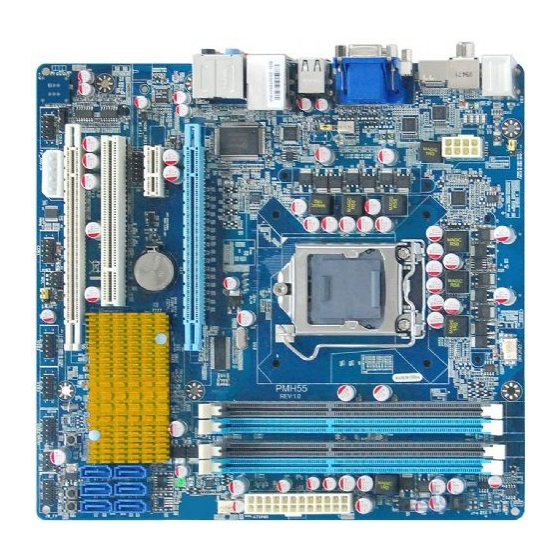
Page 10: Layout Diagram
4-pin PWR Connector VGA Connector HDMI Connector DVI Connector USB Connectors CPU FAN1 G.P.I LED CPU Socket SYSFAN2 Gigabit LAN Chip Intel H55 Chipset JBAT Wi-Fi Header Wi-Fi Header COM Header IR Header Line-IN RJ-45 LAN RS-OUT Line-OUT CS-OUT SS-OUT... - Page 11 Jumpers Jumper JBAT CMOS RAM Clear KB/MS Power On Enabled/Disabled JP2/ JP3 USB Power On Enabled/Disabled Connectors Connector ATXPWR ATX Power Connector ATX12V ATX 12V Power Connector Large 4-pin Power Connector PS/2 Mouse & PS/2 Keyboard Connector USB from UL1 and USB 2.0 Port Connectors USB1 RJ 45 LAN from UL1...
-
Page 12: Chapter 2 Hardware Installation
WARNING! Turn off your power when adding or removing expansion cards or other system components. Failure to do so may cause severe damage to both your motherboard and expansion cards. Hardware installation Steps Before using your computer, you had better complete the following steps: 1. -
Page 13: Installing Cpu
(2) KB/MS Power on Function Enabled/Disabled: JP1 1-2 Closed KB/MS Power ON Disable (Default) 2-3 Closed KB/MS Power ON Enabled Keyboard/Mouse Power On Setting (3) USB Power On function Enabled/Disabled: JP2/JP3 JP2 / JP3 JP2/ JP3 1-2 closed USB Power On Disable 2-3 closed USB Power On Enabled (Default) -
Page 14: About Intel Lga 1156 Cpu Socket
CPU, DRAM and PCI BUS. CPU L2 Cache - the flash memory inside the CPU, normal it depend on CPU type. 2-3-2 About Intel LGA 1156 CPU Socket This motherboard provides an 1156-pin DIP, LGA 1156 Land Grid Array socket, referred to as the LGA 1156 socket. -
Page 15: Lga 1156 Cpu Installation Guide
2-3-3 LGA 1156 CPU Installation Guide Please make sure that CPU socket is facing towards you and the level is on you left hand side. Open the level upwards about 135 degree and the metal protection plate will be pulled up at the same time. -
Page 16: Intel Reference Thermal Solution Assembly
The heat sink and installation steps are for reference use only; Installation steps might differ depending on different heat sink models; Please use Intel original heat sink for better heat dissipation or other heat sinks that has pass Intel certification. -
Page 17: Install Memory
Install Memory This motherboard provides four 240-pin DDR III DUAL INLINE MEMORY MODULES (DIMM) socket for DDR III memory expansion available to maximum memory volume of 16GB DDRIII SDRAM. Valid Memory Configurations Bank DIMM1 DIMM2 DIMM3 DIMM4 Total Recommend DIMM Module Combination One DDRIII Memory Module ----Plug in DIMMM1. -
Page 18: Installation Tips
Installation Tips: Open the two plastic clips of memory slots then push down the module vertically into the slot. See to it that the hole of the module fit into the notch of the slot; The two plastic clips will automatically close if the memory module is fitted in a proper way. -
Page 19: Pci-Express Slot
2-5-3 PCI Express Slot The H55 Express chipset based motherboard series offer two PCI-Express2.0 x16 graphics slots. With PE1 being PCI Express 2.0 x16by16 lane slot and PE3 being PCI Express 2.0 x16by4 lane slot. These two graphics slots are fully compatible with the latest AMD CrossFireX Technology to guarantee the fully operational Multi-GPUs graphics function and avoid the possible installation error. -
Page 20: Connectors, Headers
3. Be careful with the position for the pin you would like to set up. Notice! The motherboard and graphics card illustrations are for reference use only; We suggest that you install graphics cards in PE1 and PE3 slot for better CrossFire performance;... - Page 21 ** If you are using a 20-pin power plug, please refer to Figure1 for power supply connection. Power plug form power supply and power connectors from motherboard both adopt key design to avoid mistake installation. You can insert the power plug into the connector with ease only in the right direction. If the direction is wrong it is hard to fit in and if you make the connection by force if is possible.
- Page 22 (3) Large 4-Pin Power Connector:J1 The connectors are 4-pin connector that supports extra 12V / 5V power to your system (4) PS/2 Mouse & PS/2 Keyboard Connector: KB1 The connectors are for PS/2 keyboard and PS/2 Mouse. (5) USB Port connector: USB port fromUL1, USB1 The connectors are 4-pin connectors that connect USB devices with the 480 Mbit / sec data transfer rate to the system board.
-
Page 23: Headers
(8) Serial-ATA2 Port connectors: SATA1~SATA6 These connectors support the provided Serial ATA and Serial ATA2 IDE hard disk cable to connect the motherboard and serial ATA2 hard disk drives. (9) SPDIF Out connectors: SPDIF_OUT/SPDIF_OUT2 The SPDIF output is capable of providing digital audio to external speakers or compressed AC3 data to an external Dolby digital decoder. - Page 24 (3) Speaker connector: SPEAK This 4-pin connector connects to the case-mounted speaker. See the figure below. (4) Power LED: PWR LED The Power LED is light on while the system power is on. Connect the Power LED from the system case to this pin. (5) IDE Activity LED: HD LED This connector connects to the hard disk activity indicator light on the case.
- Page 25 (9) CD Audio-In Headers (4-pin): CDIN CDIN are the connectors for CD-Audio Input signal. CD-ROM CD-Audio output connector. (10) IR infrared module Headers (5-pin): IR1 This connector supports the optional wireless transmitting and receiving infrared module. You must configure the setting through the BIOS setup to use the IR function.
- Page 26 (12) SPDIF Out header: HDMI_SPDIF The SPDIF output is capable of providing digital audio to external speakers or compressed AC3 data to an external Dolby digital decoder. Use this feature only when your stereo system has digital input function. (13) WI-FI Header: WI-FI 1 This header supports WI-FI Function.
-
Page 27: Starting Up Your Computer
Starting Up Your Computer 1. After all connection is made, close your computer case cover. 2. Be sure all the switch are off, and check that the power supply input voltage is set to proper position, usually in-put voltage is 220V∼240V or 110V∼120V depending on your country’s voltage used. -
Page 28: Chapter 3 Introducing Bios
The BIOS is a program located on a Flash Memory on the motherboard. This program is a bridge between motherboard and operating system. When you start the computer, the BIOS program will gain control. auto-diagnostic test called POST (power on self test) for all the necessary hardware, it detects the entire hardware device and configures the parameters of the hardware synchronization. -
Page 29: The Main Menu
The Main Menu Once you enter AMI BIOS Setup Utility, the Main Menu (Figure 3-1) will appear on the screen. The Main Menu allows you to select from 12 setup functions and 2 exit choices. Use arrow keys to select among the items and press <Enter> to accept or enter the sub-menu. -
Page 30: Standard Bios Features
Change User Password This entry for setting User password Save Changes and Exit Save CMOS value changes to CMOS and exit setup. Discard Changes and Exit Abandon all CMOS value changes and exit setup. Standard BIOS Features The items in Standard CMOS Setup Menu are divided into several categories. Eachcategory includes no, one or more than one setup items. -
Page 31: Advanced Bios Features
3-5 Advanced BIOS Features Boot Sector Virus Protection The selection Allow you to choose the VIRUS Warning feature for IDE Hard Disk boot sector protection. If this function is enabled and someone attempt to write data into this area, BIOS will show a warning message on screen and alarm beep. Disabled (default) No warning message to appear when anything attempts to access the boot sector or hard disk partition table. -
Page 32: Cpu Features
Intel (R) Virtualization Tech When this item is set as Enabled, a VMM can utilize the additional HW Caps. Provided by Intel(R) Virtulization Tech. Note: A full reset is required to change the setting. The optional settings are: Enabled; Disabled. -
Page 33: Advanced Chipset Features
Intel(R) SpeedStep (tm) tech The optional settings are: Enabled; Disabled. Disable: Disable GV3; Enabe: Enable GV3. InteL(R) TurboMode tech Turbo mode allows processor cores to run faster than marked frequency in specific condition. Intel(R) C-STATE tech CState: CPU idle is set to C2/C3/C4. -
Page 34: Integrated Peripherals
3-7 Integrated Peripherals Configure SATA#1 as Press Enter to select the SATA type. The optional settings are: IDE; AHCI and Disabled. SATA#1 IDE Configuration The optional settings are: Compatible and Enhanced. SATA#2 IDE Configuration The optional settings are: Disabled and Enhanced. Onboard PCIE Lan Controller Use this item to enable or disable onboard PCIE Lan controller. -
Page 35: Power Management Setup
3-8 Power Management Setup The Power Management Setup allows you to configure your system to most effectively save energy saving while operating in a manner consistent with your own style of computer use. ACPI Version Features The optional settings are: ACPI v1.0; ACPI v2.0; ACPI v3.0. Enable RSDP pointers to 64-bit Fixed SYSTEM Description Tables. -
Page 36: Miscellaneous Control
High Performance Event Timer The optional settings are: Enabled; Disabled. Resume On RTC Alarm Use this item to disable or enable RTC to generate a wake event. 3-9 Miscellaneous Control Palette Snooping The optional settings are: Enabled; Disabled. Enable: inform the PCI device that an ISA graphics devices is installed in the system so the card will function correctly. -
Page 37: User Overclock Settings
CPUFAN1 Mode Setting Press enter to select CPU Mode setting, the optional settings are: Manual Mode; Thermal Cruise Mode; Speed Cruise Mode; Smart FAN III Mode. 3-11 User Overclok Settings Linear PCIEX Clock Use this item to set Linear PCIEX clock in the range of 100 to 200. CPU Diff AMP The optional settings are: 700mV;... -
Page 38: Password Settings
Use this item to set CPU VTT voltage from 1.140Vto 2.247V. The default value is 1.176v. DRAM Voltage Select Use this item to set DRAM voltage from 1.538V (Default) to2.204V. The default value is 1.589v. CPU AGX Voltage Select The optional settings are: Auto, +50mV~+350 mV. If set the voltage too high (+250mV~+350 mV), the color of the word will changed. -
Page 39: Load Optimal Defaults/Load Standard Defaults
3-13 Load Optimal Defaults/ Load Standard Defaults Load Optimal Defaults When you press <Enter> on this item, you get a confirmation dialog box with a message similar to: Pressing <OK> loads the default values that are factory settings for optimal performance system operations. -
Page 40: Chapter 4 Driver Installation
If the menu does not appear, double-click MY COMPUTER / double-click CD-ROM drive. From MENU you may make as selections: 1. INF install Intel INF chipset system driver 2. IMSS install Intel IMSS chipset system driver 3. VGA install VGA driver 4. -
Page 41: Inf: Install Intel Inf Chipset System Driver
4-1 INF: Install Intel INF Chipset System Driver Windows XP Windows XP 64 Windows VISTA/ VISTA 64/ 7 x86/ 7 x64... -
Page 42: Imss: Install Intel Imss Chipset System Driver
4-2 IMSS: Install Intel IMSS Chipset System Driver Windows XP Windows XP 64 Windows VISTA/ VISTA 64/ 7 x86/ 7 x64... -
Page 43: Vga: Install Vga Driver
4-3 VGA: Install VGA Driver Windows XP Windows XP 64 Windows VISTA/ VISTA 64/ 7 x86/ 7 x64... -
Page 44: Lan: Gigabit Ethernet Lan Driver
4-4 LAN: Gigabit Ethernet LAN Driver Windows XP Windows XP 64 Windows VISTA/ VISTA 64/ 7 x86/ 7 x64... -
Page 45: Sound: Install Audio Codec Driver
4-5 SOUND: Install Audio Codec Driver Windows XP Windows XP 64 Windows VISTA/ VISTA 64/ 7 x86/ 7 x64... -
Page 46: Ahci: Install Intel Ahci Driver
4-6 AHCI: Install Intel AHCI Driver Windows XP Windows XP 64 Windows VISTA/ VISTA 64/ 7 x86/ 7 x64... -
Page 47: User's Manual
4-7 User’s Manual 4-8 How to Update BIOS STEP 1. Prepare a bootable disk. (You may make one by click START click RUN type SYS A: click OK) STEP 2. Download upgrade tools and the latest BIOS files of the motherboard from official website and then make a copy of it to your bootable floppy disk after decompressing these files STEP 3. -
Page 48: Function Led Display
4-9 G.P.I. Function LED Display All LED off or glitter. It means the motherboard in the G.P.I mode. CPU works with the low power consumption. Three LED off or glitter. It means the motherboard is working on partial power saving mode.
Need help?
Do you have a question about the PMH55 and is the answer not in the manual?
Questions and answers