Table of Contents
Advertisement
Quick Links
Important Information
Copyright
This publication, including all photographs, illustrations and
software, is protected under international copyright laws, with all
rights reserved. Neither this manual, nor any of the material
contained herein, may be reproduced without the express writ-
ten consent of the manufacturer.
Version 1.0
Disclaimer
The information in this document is subject to change without
notice. The manufacturer makes no representations or warranti-
es with respect to the contents hereof and specifically disclaims
any implied warranties of merchantability or fitness for any par-
ticular purpose. Further, the manufacturer reserves the right to
revise this publication and to make changes from time to time in
the content hereof without obligation of the manufacturer to no-
tify any person of such revision or changes.
i
Advertisement
Table of Contents

Related Manuals for MATSONIC MS7177C


Summary of Contents for MATSONIC MS7177C
-
Page 1: Important Information
Important Information Copyright This publication, including all photographs, illustrations and software, is protected under international copyright laws, with all rights reserved. Neither this manual, nor any of the material contained herein, may be reproduced without the express writ- ten consent of the manufacturer. Version 1.0 Disclaimer The information in this document is subject to change without... -
Page 2: Trademark Recognition
Trademark Recognition Microsoft, MS-DOS and Windows are registered trademarks of Microsoft Corp. MMX, Pentium, Pentium-II, Pentium-III, Celeron are registered trademarks of Intel Corporation. Other product names used in this manual are the properties of their respective owners and are acknowledged. Federal Communications Commission (FCC) This equipment has been tested and found to comply with the limits for a Class B digital device, pursuant to Part 15 of the FCC... -
Page 3: Declaration Of Conformity
Declaration of Conformity This device complies with part 15 of the FCC rules. Operation is subject to the following conditions: ! This device may not cause harmful interference, and ! This device must accept any interference received, in- cluding interference that may cause undesired operation. Canadian Department of Communications This class B digital apparatus meets all requirements of the Ca- nadian Interference-causing Equipment Regulations. -
Page 4: About The Manual
About the Manual The manual consists of the following chapters: Introduction Use the Introduction Chapter to learn about the features of the mainboard, and verify the checklist of items that are shipped with the package. Installation Use the Installation Chapter to learn how to install the main- board and get your system up and running. -
Page 5: Table Of Contents
Contents Important Information Copyright Disclaimer Trademark Recognition Federal Communications Commission (FCC) Declaration of Conformity Canadian Department of Communications About the Manual CHAPTER 1: INTRODUCTION Welcome Checklist Recommendations Features CHAPTER 2: INSTALLATION Quick Installation Table Quick Jumper Setting Reference Before You Begin Static Electricity Choosing a Case How to Set Jumpers... - Page 6 Load Optimized Defaults Option Set Supervisor and User Passwords Options Save & Exit Setup Option Exit Without Saving Option CHAPTER 4: SOFTWARE Folders for this Mainboard Utility Folder Installation Notes Mainboard (MS7177C) Installation Notes APPENDIX: JUMPER SETTING REFERENCE Quick Jumper Setting Reference...
-
Page 7: Chapter 1: Introduction
The mainboard accommodates PC 100 SDRAM (Synchronous DRAM) up to 1.5 GB using three 3.3V unbuffered DIMM modules. The MS7177C also has a full set of I/O ports, such as dual channel IDE interfaces, a floppy controller, two FIFO serial port connectors,... -
Page 8: Checklist
This chapter contains the following information: ! Checklist comprises a list of the standard and optional components that are shipped with this mainboard ! Recommendations lists some Do’s and Don’ts from the manufacturer to help ensure reliability and performance from this product ! Features highlights the functions and components that make this one of the best value mainboards on the mar- Checklist... -
Page 9: Recommendations
Recommendations This mainboard automatically determines the CPU clock fre- quency and system bus frequency for the kind of processor that you install. You may be able to change these automatic settings by making changes to jumpers on the mainboard, or changing the settings in the system Setup Utility. -
Page 10: Features
Value-class Processors Functioning as a platform for a value PC, the MS7177C features a Socket 370 that accommodates PPGA Celeron, Pentium III, and Cyrix III processors. The MS7177C supports 66/100/133 MHz FSB speeds. - Page 11 As an option you can get the MS7177C with the VIA VT82C686B SB chipset, which supports UDMA100. The Real Time Clock features extended 256 byte CMOS RAM and a day and month alarm for the ACPI (Advanced Configura- tion and Power Interface).
- Page 12 Further features include support for four analog line-level stereo inputs. Expansion Options Five 32-bit PCI slots, an AGP slot, and an AMR slot provide plenty of expansion potential. The MS7177C PCI slots support Ultra DMA33/66 bus mastering with transfer rates up to 33/66 MB/sec. Integrated I/O The mainboard has a full set of I/O ports and connectors.
-
Page 13: Chapter 2: Installation
Quick Installation Table This chapter explains how to successfully install the mainboard into a computer case and build a working system. The installa- tion procedure is as follows: Quick Jumper Provides a quick reference for the jumper Setting settings on this mainboard. Reference Before you Provides advice on choosing a case,... -
Page 14: Quick Jumper Setting Reference
Quick Jumper Setting Reference If you are familiar with most of the material in this chapter, you can prepare the mainboard for installation by using this quick reference to set the jumpers. A detailed description of the jum- per setting appears later in this chapter. JP1: Clear CMOS jumper Use this jumper to clear the contents of the CMOS memory. - Page 15 JP7: CPU frequency select jumper Use this jumper to force a CPU that has a 66 MHz frontside bus (FSB) to run at a 100 MHz FSB speed. Function Jumper Setting Normal operation Short pins 1-2 Force a 66 MHz FSB to Short pins 2-3 run at 100 MHz FSB Note: The CPU speed is determined by the CPU Host/PCI Clock...
- Page 16 JP16: Dual color LED header This header allows the user to install red and green LED indica- tors to indicate when the computer is in Suspend to RAM (STR) or normal. Although the values are not predefined, red usually indicates STR and green indicates normal. JP17: USB2 wake up jumper Use this jumper to enable a signal to the USB devices 3 and 4 (located on the front panel) to wake up the system from power...
- Page 17 PANEL1: Panel connectors for switches and indicators Use the panel connector to implement the switches and indica- tors on your system case. Panel connectors for switches and indicators Function Pins PANEL1 Power switch +22, 23 Hard disk LED Indicator +20, 21 Power Switch 22-23 Empty pin HDD LED 20-21...
-
Page 18: Before You Begin
Before You Begin Before you begin to install your mainboard, take care not to damage the product from static electricity. Ensure too that you are installing the mainboard into a suitable case. Static Electricity In adverse conditions, static electricity can accumulate and dis- charge through the integrated circuits and silicon chips on this product. -
Page 19: How To Set Jumpers
How to Set Jumpers A jumper consists of two or more pins mounted on the main- board. Some jumpers might be arranged in a series with each pair of pins numbered differently. Jumpers are used to change the electronic circuits on the mainboard. When a jumper cap (or shunt) is placed on two jumper pins, the pins are SHORT. -
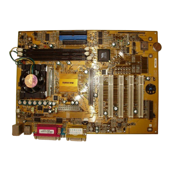
Page 20: Preparing The Mainboard
Preparing the Mainboard Mainboard Guide Use the following illustration and key to identify the components on your mainboard. PWRFAN1 DIMM 1 DIMM 2 DIMM 3 PW RFA N1 CPUFAN1 C PUFA N1 ATX1 Socket 370 LED1 L ED1 IDE2 IDE1 FDD1 C D1 C D2... - Page 21 Key to Mainboard Components Component Description PWRFAN1 Power connector for case cooling fan USB wake up select jumper Extra IR/KB/Mouse header PGA370 CPU socket CPUFAN1 Power connector for CPU cooling fan DIMM 1, 2, 3 Three slots for 168-pin DRAM memory module Suspend to RAM support jumper JP7, 8, CPU frequency select jumper...
-
Page 22: I/O Ports Side View
I/O Ports Side View Parallel port (LPT1) PS/2 Gam e port m ouse PS/2 Serial port Serial port M icrophone keyboard ports COM 1 COM 2 Line-in Line-out Key to I/O Ports Component Description PS/2 mouse PS/2 port for pointing device (upper port) PS/2 keyboard PS/2 port for keyboard (lower port) USB ports... -
Page 23: Check The Jumper Settings
Check the Jumper Settings Check the mainboard jumpers to ensure that the board is con- figured correctly. JP 5 JP 6 JP 7 JP 8 JP 17 JP 16 JP 14 JP 18 JP 19 JP 1 JP1: Clear CMOS jumper Use this jumper to clear the contents of the CMOS memory. - Page 24 Return the jumper cap to the Normal operation setting. Recon- nect the power cables and start the system. When the POST starts, press the delete key to start the BIOS Setup Utility and reload BIOS optimal settings. Refer to Chapter 3 for information on BIOS.
- Page 25 JP8: CPU frequency select jumper This jumper enables you to force the CPU to clock at a higher frequency than it is rated. Short pins 2 and 3 to force the CPU to run at a 133 MHz FSB instead of a 100 MHz FSB. We recom- mend that you leave the jumper on the normal operation setting.
- Page 26 JP18: BIOS Flash protect jumper Use this jumper to enable or disable the BIOS flash protection on the mainboard. You should disable this jumper when you want to flash the BIOS. Function Jumper Setting JP18 Disable Short pins 1-2 Enable Short pins 2-3 JP19: AMR codec mode Use this jumper to define the AMR codec mode and avoid con-...
-
Page 27: Installing The Mainboard In A Case
Installing the Mainboard in a Case Most system cases have mounting brackets installed in the case, which correspond to the holes in the mainboard. Place the mainboard over the mounting brackets and secure the main- board into the mounting brackets with screws. Most cases have a choice of I/O templates in the rear panel. -
Page 28: Connecting Internal Components
Connecting Internal Components After you have installed the mainboard into the system case, connect the power cable from the case power supply unit to the mainboard power connector ATX1. Your case and CPU might have cooling fans attached to provide adequate ventilation to the system. -
Page 29: Panel Connector
Panel Connector The mainboard PANEL connector has a standard set of switch and indicator connectors that are commonly found on ATX sys- tem cases. Use the illustration below to make the correct connections to the case switches and indicators. Panel connectors for switches and indicators Function Pins PANEL1... -
Page 30: Installing Other Hardware
Installing Other Hardware Install the essential hardware required to get your system started. Installing the Processor This mainboard has a Socket 370 processor socket. To choose a processor, you need to consider the performance require- ments of the system and the price of the processor. Performance is based on the processor design, the clock speed and system bus frequency of the processor, and the quantity of internal cache memory and external cache memory. - Page 31 2. On the Socket 370, pull the locking lever away from the socket to unhook it and then raise the locking lever to the upright position. 3. Identify the pin-1 corner on the Socket 370 and the pin-1 corner on the processor. The socket pin-1 corner is adjacent to the handle of the locking lever.
-
Page 32: Install The Memory Modules
Install the Memory Modules For this mainboard, you must use 168-pin 3.3V non-buffered Dual In-line Memory Modules (DIMMs). The memory chips must be standard or registered SDRAM and VCM SDRAM memory chips. The memory bus can run at 66 MHz, 100 MHz, or 133 MHz. -
Page 33: Installation Procedure
Installation Procedure There are three slots for memory modules. You must install at least one module, and it makes no difference which slot you use to install the module. Each module can be populated with from 32 MB to 512 MB of memory; total memory capacity is 1.5 GB. 1. -
Page 34: Installing A Hard Disk Drive And Cd-Rom
IDE devices that support UDMA, and use IDE cables that support UDMA. Note: The MS7177C supports two VIA South Bridge chipsets— the VIA VT82C686A and the VIA VT82C686B. The VIA VT82C686A is standard and supports UDMA33/66. The VIA... -
Page 35: Installing A Hard Disk Drive
Installing a Hard Disk Drive 1. Install the hard disk drive into the drive cage in your system case. 2. Plug the IDE cable into the primary IDE channel on the mainboard IDE1. 3. Plug one of the connectors on the IDE cable into the IDE connector on the back edge of the hard disk drive. - Page 36 Installing a CD-ROM/DVD Drive 1. Install the CD-ROM/DVD drive into the drive cage in your system case. Plug the IDE cable into the primary IDE chan- nel on the mainboard IDE1. 2. Plug one of the connectors on the IDE cable into the IDE connector on the back edge of the CD-ROM/DVD drive.
-
Page 37: Installing A Floppy Diskette Drive
Installing a Floppy Diskette Drive The mainboard has a floppy diskette drive interface and it ships with a diskette drive ribbon cable that supports one or two floppy diskette drives. You can install a 5.25-inch drive and a 3.5-inch drive with various capacities. The floppy diskette drive cable has one type of connector for a 5.25-inch drive and another type of connector for a 5.25-inch drive 1. -
Page 38: Using The Expansion Slots
Using the Expansion Slots This mainboard has five 32-bit PCI expansion slots, one 4xAGP slot, and an AMR slot. PCI Slots: The PCI slots can be used to install add-in cards that have the 32-bit PCI (Peripheral Components Interconnect) in- terface. - Page 39 1. Before installing an expansion card, check the documenta- tion for the card carefully. If the card is not Plug and Play, you may have to manually configure the card before instal- lation. add-in card M etal bracket PCI slot Edge Connector 2.
- Page 40 The following illustration shows how to insert an AMR card: Edge AMR card Connector AMR slot...
-
Page 41: Add-In Card Options
Add-in Card Options PW RFAN1 CPUFAN1 LED1 AGP1 W O M 1 W O L1 PCI1 PCI2 SIR1 LED2 PCI3 JP17 W OM1 W OL1 PCI4 USB2 PCI5 JP16 JP18 AMR1 USB2 J1: Extra IR/keyboard/mouse header This mainboard provides a second infrared, keyboard, and mouse header, giving the option of installing second infrared, keyboard, and mouse ports on the front panel. - Page 42 SIR1: Infrared Port This mainboard can support a Serial Infrared (SIR) data port. In- frared ports allow the wireless exchange of information between your computer and similarly equipped devices such as printers, laptops, Personal Digital Assistants (PDA), and other desktop computers.
-
Page 43: Making External Connections
Making External Connections After you have installed the mainboard, make the connections to the external ports. Parallel port (LPT1) PS/2 G am e port m ouse PS/2 Serial port Serial port M icrophone keyboard ports C O M 1 C O M 2 Line-in Line-out 1. -
Page 44: External Connector Color Coding
External Connector Color Coding To help identify the external connectors, many connectors now use standard colors as shown in the table below. Connector Color Analog VGA Blue Audio line in Light blue Audio line out Lime Digital monitor / flat panel White IEEE 1394 Grey... -
Page 45: Chapter 3: Setup
About the Setup Utility The computer employs the latest Award BIOS CMOS chip with support for Windows Plug and Play. This CMOS chip contains the ROM setup instructions for configuring the mainboard’s BIOS. The BIOS (Basic Input and Output System) Setup Utility is a ROM-based configuration utility that displays the system’s configuration status and provides you with a tool to set system parameters. -
Page 46: Entering The Setup Utility
A standard configuration has already been set in the Setup Util- ity, so you will very likely have little to worry about for now. However, we recommend that you read this chapter just in case you need to make any changes in the future. This program should be executed under the following conditions: When changing the system configuration When a configuration error is detected by the system and... -
Page 47: Bios Navigation Keys
After the POST routines are completed, the following message appears: Press DEL to enter SETUP To access the Award BIOS Setup Utility, press the delete key to display the “CMOS Setup Utility” screen: CMOS Setup Utility – Copyright (C) 1984 – 2000 Award Software Standard CMOS Features Frequency/Voltage Control Advanced BIOS Features... -
Page 48: Using Bios
Using BIOS When you start the Setup Utility, the main menu appears. The main menu of the Setup Utility shows a list of the options that are available. A highlight indicates which option is currently se- lected. You can use the cursor arrow keys to move the highlight to other options. -
Page 49: How To Flash A New Bios
How to Flash a New BIOS You can install updated BIOS for this mainboard that you can download from the manufacturer’s web site. New BIOS may provide support for new peripherals, improvements in performance or fixes for known bugs. Install new BIOS as follows: 1. -
Page 50: Standard Cmos Setup Option
8. In the “File Name to Program” dialog box, type in the file- name of the new BIOS and follow the onscreen directions to flash the new BIOS to the mainboard. 9. When the installation is complete, remove the floppy diskette from the diskette drive and restart your computer. - Page 51 CMOS Setup Utility – Copyright (C) 1984 – 2000 Award Software IDE Primary Master IDE HDD Auto-Detection Press Enter Item Help IDE Primary Master Auto Menu Level Access Mode Auto To auto-detect the Capacity 8448 MB HDD’s size, head . . . on Cylinder 16368 this channel...
- Page 52 Access Mode This items defines some special ways that can be used to access IDE hard disks such as LBA (Large Block Addressing). Leave this value at Auto and the system will automatically decide the fastest way to access the hard disk drive. Press <Esc>...
-
Page 53: Advanced Cmos Setup Option
Advanced CMOS Setup Option This option displays a table of items that define advanced infor- mation about your system. You can make modifications to most of these items without introducing fatal errors to your system. Use the arrow keys to scroll down to the items past “Boot to OS/2.”... - Page 54 H/W Reset Function Default: Enabled Enables or disables the computer’s hardware reset button. The default setting is Enabled. CPU Internal Cache CPU Internal Cache Default: Enabled All the processors that can be installed in this mainboard use internal level 1 (L1) cache memory to improve performance. Leave this item at the default value Enabled for better performance.
- Page 55 Swap Floppy Drive Default: Disabled If you have two floppy diskette drives in your system, this item allows you to swap the assigned drive letters so that drive A becomes drive B, and drive B becomes drive A. Boot Up Floppy Seek Default: Enabled If this item is enabled, it checks the geometry of the floppy disk drives at start-up time.
- Page 56 OS Select For DRAM > 64 MB Default: Non-OS2 This item is only required if you have installed more than 64 MB of memory and you are running the OS/2 operating system. Otherwise, leave this item at the default Non-OS2. HDD S.M.A.R.T Capability Default: Disabled The S.M.A.R.T.
-
Page 57: Advanced Chipset Features Option
Advanced Chipset Features Option This option displays a table of items that define critical timing parameters of the mainboard components including the memory, and the system logic. Generally, you should leave the items on this page at their default values unless you are very familiar with the technical specifications of your system hardware. - Page 58 DRAM Clock Default: Host CLK This item sets the DRAM Clock. We recommend that you leave this item at the default value. Memory Hole Default: Disabled This item can be used to reserve memory space for some ISA expan- sion cards that require it. P2C/C2P Concurrency Default: Enabled When disabled, the CPU bus is occupied during the entire PCI opera-...
- Page 59 AGP Driving Value Default: DA When the previous item AGP Driving Control is set to Manual, you can use this item to set the AGP current driving value. AGP Fast Write Default: Disabled This item allows you to enable or disable the caching of display data for the video memory of the processor.
- Page 60 PCI Delay Transaction Default: Enabled The chipset has an embedded 32-bit posted write buffer to support de- lay transactions cycles. Select Enabled to support compliance with PCI specification version 2.1. PCI#2 Access #1 Retry Default: Enabled When set to Enabled, the AGP Bus (PCI#2) access to PCI Bus (PCI#1) is executed with the error retry feature.
-
Page 61: Integrated Peripherals Option
Integrated Peripherals Option This option displays a list of items that defines the operation of some peripheral components on the system’s input/output ports. CMOS Setup Utility – Copyright (C) 1984 – 2000 Award Software Integrated Peripherals OnChip IDE Channel0 Enabled Item Help OnChip IDE Channel1... - Page 62 Init Display First Default: PCI Slot Use this item to define if your graphics adapter is installed in one of the PCI slots or select Onboard if you have a graphics system integrated on the mainboard. IDE HDD Block Mode Default: Enabled Enable this field if your IDE hard drive supports block mode.
- Page 63 TX,RX inverting enable Default: No, Yes Defines the voltage level for Infrared module RxD (receive) mode and TxD (transmit) mode. This setting has to match the requirements of the infrared module used in the system. Onboard Parallel Port Default: 378/IRQ7 This option is used to assign the I/O address for the onboard parallel port.
-
Page 64: Power Management Setup Option
SB IRQ Select Default: IRQ 5 This item lets you set the Interrupt Request (IRQ) for the Sound Blaster card. SB DMA Select Default: DMA 1 This item lets you select the DMA for the Sound Blaster card. MPU-401 Default: Enabled Use this item to enable or disable the MPU-401 (MIDI) function for the game port. - Page 65 Wake Up Calls If the system is suspended, or has been powered down by soft- ware, it can be resumed by a wake up call that is generated by incoming traffic to a modem, a LAN card, a PCI card, or a fixed alarm on the system realtime clock, CMOS Setup Utility –...
- Page 66 CMOS Setup Utility – Copyright (C) 1984 – 2000 Award Software Power Management Power Management User Define Item Help HDD Power Down Disable Doze Mode Disabled Menu Level Suspend Mode Disable : Move Enter : Select +/-/PU/PD:Value: F10: Save ESC: Exit F1:General Help F5:Previous Values F6:Fail-Safe Defaults...
- Page 67 ACPI Suspend Type Default: S1 (POS) Use this item to define how your system suspends. In the default, S1(POS), the suspend mode is equivalent to a software power down. If you select S3 (STR), the suspend mode is a suspend to RAM – the system shuts down with the exception of a refresh current to the system memory.
- Page 68 Wake Up Events This item opens a submenu that enables you to set events that will re- sume the system from a power saving mode. Select Wake Up Events and press Enter to display the following menu: CMOS Setup Utility – Copyright (C) 1984 – 2000 Award Software Wake Up Events USB Resume from S3/S4/S5 Disabled...
- Page 69 PowerOn by PCI Card Default: Disabled Use this item to enable PCI activity to wakeup the system from a power saving mode. Wake Up On LAN/Ring Default: Disabled Use this item to enable LAN or modem activity to wakeup the system from a power saving mode.
-
Page 70: Pnp/Pci Configuration Option
PNP/PCI Configuration Option This option displays a table of items that configures how PnP (Plug and Play) and PCI expansion cards operate in your system. Both the ISA and PCI buses on the Mainboard use system IRQs (Inter- rupt ReQuests) and DMAs (Direct Memory Access). You must set up the IRQ and DMA assignments correctly through the PnP/PCI Configurations Setup utility;... - Page 71 Resources Controlled By Default: Auto(ESCD) You should leave this item at the default Auto(ESCD). Under this set- ting, the system dynamically allocates resources to plug and play devices as they are required. If you cannot get a legacy ISA (Industry Standard Architecture) expan- sion card to work properly, you might be able to solve the problem by changing this item to Manual, and then opening up the IRQ Resources and Memory Resources sub-menus.
-
Page 72: Pci Health Status Option
PCI Health Status Option On mainboards that support hardware monitoring, this item lets you monitor the parameters for critical voltages, critical tem- peratures, and fan speeds. You cannot make any changes to these fields. They are display only: CMOS Setup Utility – Copyright (C) 1984 – 2000 Award Software PC Health Status Shutdown Temperature Disabled... -
Page 73: Frequency Control Option
Frequency Control Option This item enables you to set the clock speed and system bus for your system. The clock speed and system bus are determined by the kind of processor you have installed in your system. CMOS Setup Utility – Copyright (C) 1984 – 2000 Award Software Frequency Control Auto Detect DIMM/PCI Clk Enabled... -
Page 74: Load Fail-Safe Defaults Option
CPU Clock Ratio Default: Auto Use this item to select a multiplier for the system frontside bus (FSB) frequency. The value of the multiplier must be set so that: Multiplier x Frontside Bus Frequency = CPU Clock Speed For example, if you have a processor that is rated to run at 450 MHz and the system is running a frontside bus frequency of 100 MHz, you should select a multiplier of 4.5 so that: 4.5 (Multiplier) x 100 MHz (frontside bus) = 450 MHz (CPU clock) -
Page 75: Set Supervisor And User Passwords Options
Set Supervisor and User Passwords Options These items can be used to install a password. A Supervisor password takes precedence over a User password, and the Su- pervisor can limit the activities of a User. To install a password, follow these steps: 1. -
Page 76: Save & Exit Setup Option
Save & Exit Setup Option Highlight this item and press <Enter> to save the changes that you have made in the Setup Utility and exit the Setup Utility. When the Save and Exit dialog box appears, press <Y> to save and exit, or press <N>... -
Page 77: Chapter 4: Software
INTEL and VIA folders. In addition, software that is specifically in- tended for one kind of mainboard is stored in a folder with the name of that board. The software for this mainboard is stored in the MS7177C folder. Note: Never try to install software from a folder that is not specified for use with your mainboard. -
Page 78: Utility Folder Installation Notes
MS7177C Folder You can use the software in the following sub-folders: AUDIO and IDE: Most of the sub-folders in this folder are empty, with a short README file giving directions to alternate folders for the appropriate software. Running the Support CD-ROM 1. -
Page 79: Mediaring Talk
PC-cillin Software The PC-cillin software program provides anti-virus protection for your system. This program is available for: ! DOS – \UTILITY\PC-CILLIN\DOS\PCSCAN.EXE ! Win98 – \UTILITY\PC-CILLIN\WIN98\SETUP.EXE Anti-virus software is provided for DOS and WIN95/98. Browse to the appropriate directory for your operating system. For DOS, copy all the files in the DOS folder to your hard disk drive and run PSCAN to scan your system. -
Page 80: Mainboard (Ms7177C) Installation Notes
Refer to your operating system handbook for instructions on in- stalling Linux drivers. Mainboard (MS7177C) Installation Notes Most of the sub-folders in this folder are empty, with a short READ- ME file giving directions to alternate folders for the appropriate... -
Page 81: Appendix: Jumper Setting Reference
Quick Jumper Setting Reference If you are familiar with most of the material in this chapter, you can begin preparing the mainboard for installation by using this quick reference to begin setting the jumpers. JP1: Clear CMOS jumper Use this jumper to clear the contents of the CMOS memory. Function Jumper Setting Normal operation... - Page 82 JP7: CPU frequency select jumper Use this jumper to force a CPU that has a 66 MHz frontside bus (FSB) to run at a 100 MHz FSB speed. Function Jumper Setting Normal operation Short pins 1-2 Force a 66 MHz FSB to Short pins 2-3 run at 100 MHz FSB Note: The CPU speed is determined by the CPU Host/PCI Clock...
- Page 83 JP16: Dual color LED header This header allows the user to install red and green LED indica- tors to indicate when the computer is in Suspend to RAM (STR) or normal. Although the values are not predefined, red usually indicates STR and green indicates normal. JP17: USB2 wake up jumper Use this jumper to enable a signal to the USB devices 3 and 4 (located on the front panel) to wake up the system from power...
- Page 84 PANEL1: Panel connectors for switches and indicators Use the panel connector to implement the switches and indica- tors on your system case. Panel connectors for switches and indicators Function Pins PANEL1 Power switch +22, 23 Hard disk LED Indicator +20, 21 Power Switch 22-23 Empty pin HDD LED 20-21...
Need help?
Do you have a question about the MS7177C and is the answer not in the manual?
Questions and answers