Table of Contents
Advertisement
This publication, including all photographs, illustrations and
software, is protected under international copyright laws, with all
rights reserved. Neither this manual, nor any of the material
contained herein, may be reproduced without the express written
consent of the manufacturer.
The information in this document is subject to change without
notice. The manufacturer makes no representations or warranties
with respect to the contents hereof and specifically disclaims any
implied warranties of merchantability or fitness for any particular
purpose. Further, the manufacturer reserves the right to revise this
publication and to make changes from time to time in the content
hereof without obligation of the manufacturer to notify any person
of such revision or changes.
Trademarks
IBM, VGA, OS/2, and PS/2 are registered trademarks of
International Business Machines.
Intel, Pentium, Pentium-II, Pentium-III, MMX, and Celeron are
registered trademarks of Intel Corporation.
Microsoft, MS-DOS and Windows 95/98/NT are registered
trademarks of Microsoft Corporation.
Sound Blaster and SB-Link are trademarks of Creative Technology
Ltd.
PC-cillin and ChipAway Virus are trademarks of Trend Micro Inc.
Award is a trademark of Award Software Inc.
A3D is a registered trademark of Aureal Inc.
Other names used in this publication may be trademarks and are
acknowledged.
Copyright © 1999
All Rights Reserved
MS7192S, Version 1.2
V6X/April 1999
Advertisement
Table of Contents

Related Manuals for MATSONIC MS7192S


Summary of Contents for MATSONIC MS7192S
- Page 1 PC-cillin and ChipAway Virus are trademarks of Trend Micro Inc. Award is a trademark of Award Software Inc. A3D is a registered trademark of Aureal Inc. Other names used in this publication may be trademarks and are acknowledged. Copyright © 1999 All Rights Reserved MS7192S, Version 1.2 V6X/April 1999...
-
Page 2: Declaration Of Conformity
Federal Communications Commission (FCC) This equipment has been tested and found to comply with the limits for a Class B digital device, pursuant to Part 15 of the FCC Rules. These limits are designed to provide reasonable protection against harmful interference in a residential installation. -
Page 3: Table Of Contents
Table of Contents Chapter 1 Introduction............1 Key Features................. 2 Slot-1 Processor Support............2 Socket-370 Processor Support........... 2 Memory Support............... 2 Expansion Slots ................ 2 Onboard IDE channels .............. 2 Power Supply and Power Management ........3 Sound System ................3 Onboard I/O Ports.............. - Page 4 Table of Contents Internal Sound Connections ............ 19 Expansion Slots ................20 Installing an Expansion Card ........... 20 Wake Up Connectors and Sideband1 ........21 Wake On LAN................ 21 Wake On Modem ..............21 SB-Link .................. 21 Chapter 3 BIOS Setup............22 Introduction ................
-
Page 5: Chapter 1 Introduction
Chapter 1 Introduction This mainboard provides very high performance as it supports all of Intel’ s Slot-1 processors including the Pentium-III, the Pentium-II, and the SEPP (Single Edge Processor Package) Celeron. Pentium-III processors run at clock rates of 450 and 500. Pentium-II processors run from 233 MHz through to 450 MHz, and the SEPP Celerons run from 266 up to 433 MHz. -
Page 6: Key Features
Chapter 1 Key Features This key features of this mainboard include: Slot-1 Processor Support Pentium-III support for 450 MHz and 500 MHz clock rates Pentium-II support for 233 MHz to 450 MHz clock rates SEPP Celeron support for 266 MHz to 433 MHz clock rates Support for 66 MHz and 100 MHz FSB (Front Side Bus) All processors configured by CPU Plug &... -
Page 7: Power Supply And Power Management
Key Features Power Supply and Power Management Provides ATX power connector Support for Power button/Suspend Switch, and Keyboard Power On/Off (needs Win98 keyboard) Supports Wake on Modem, Wake on LAN and Wake on Alarm Sound System Meets PC98 audio specification Full duplex playback and recording with built-in 16-bit CODEC HRTF 3D professional audio supports both Direct Sound... -
Page 8: Hardware Monitoring
Chapter 1 Hardware Monitoring Built-in hardware monitoring for CPU temperature and fan speeds Supports Intel’ s LANDesk Client Manager (LDCM) Onboard Flash ROM Provides plug and play function for automatic CPU and board configuration Supports plug and play configuration of peripheral devices and expansion cards Built-in virus protection using Trend’... -
Page 9: Static Electricity Precautions
Static Electricity Precautions Static Electricity Precautions 1. Components on this mainboard can be damaged by static electricity. Take the following precautions when unpacking the mainboard and installing it in a system. 2. Keep the mainboard, and other components, in their original static-proof packaging until you are ready to install them. -
Page 10: Chapter 2 Mainboard Installation
Chapter 2 Mainboard Installation To install this mainboard into your system, follow the procedures in this chapter: Identify the mainboard components Install the correct processor Install one or more memory modules Verify that any jumpers or switches are at the correct setting Install the mainboard in the system chassis Install any other devices and make the appropriate connections to the mainboard headers. -
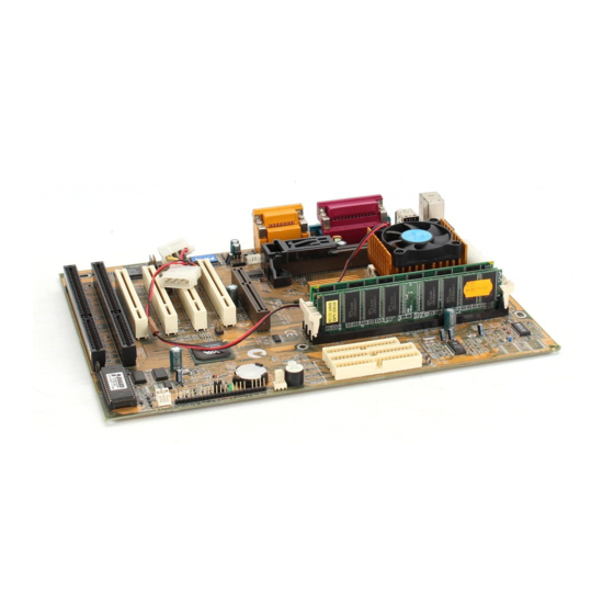
Page 11: Mainboard Components
Mainboard Components Mainboard Components Use the diagram below to identify the major components on your mainboard. SIR1 SPDIF1 Slot-1 ISA2 PCI1 ATX1 PCI2 AGP1 Socket-370 PCI3 PCI4 ISA1 CPUFAN1 Sideband1 DIMM DIMM2 DIMM3 FDD1 WOL1 IDE2 IDE1 CASEFAN1 WOM1 PANEL... -
Page 12: I/O Ports
Chapter 2 I/O Ports The illustration below shows a side view of the I/O ports installed on the mainboard. PS/2 Mouse Game/MIDI Port Parallel Port USB Ports Stereo Out PS/2 Keyboard Microphone Serial COM1/3 Serial COM2/4 Stereo In Install the Processor This mainboard has a Slot-1 which can be installed with any Slot-1 processor cartridge including the Pentium-III, the Pentium-II, and the SEPP Celeron. -
Page 13: Installing A Slot-1 Processor Cartridge
Install the Processor Processor Clock Rate Processor System Bus Cartridge Socket Pentium-III Slot-1 Pentium-III Slot-1 Pentium-II Slot-1 Pentium-II Slot-1 Pentium-II Slot-1 Pentium-II Slot-1 Pentium-II Slot-1 Pentium-II Slot-1 Pentium-II Slot-1 SEPP Celeron Slot-1 SEPP Celeron Slot-1 SEPP Celeron Slot-1 SEPP Celeron Slot-1 SEPP Celeron 300A... -
Page 14: Installing A Socket-370 Processor
Chapter 2 3. Insert the processor cartridge into the cartridge holder. Follow the instructions given with your processor cartridge. The edge connector on the cartridge has a notch so that it only fits into the Slot-1 in the correct way. 4. -
Page 15: Install Memory
Install Memory 2. On the Celeron processor, identify the pin-1 corner by noting that it has a slight bevel. 3. On the Socket-370, identify the pin-1 corner. The pin-1 corner is on the same side as the locking lever, closest to the top of the lever when it is in the locked position. -
Page 16: Set The Jumpers
Chapter 2 You can install any size of memory module from 16 MB up to 256 MB, so the maximum memory size is 3 x 256 MB = 768 MB. The edge connectors on the memory modules have cut outs, which coincide with struts in the DIMM slots, so the memory modules can only be installed in the correct way. -
Page 17: Jumper Jp1: Clear Cmos Memory
Set the Jumpers Jumper JP1: Clear CMOS Memory Use this jumper to clear the contents of the CMOS memory. You may need to clear the CMOS memory if the settings in the setup utility are incorrect and prevent your mainboard from operating. To clear the CMOS memory, disconnect all the power cables from the mainboard and then move the jumper cap into the CLEAR setting for a few seconds. -
Page 18: Jumper Jp5: Set Spdif Output Voltage
Chapter 2 Jumper JP5: Set SPDIF Output Voltage Use this jumper to select the output voltage of the digital audio SPDIF connector on this mainboard. Select either 0.5 volts or 5 volts according to the devices that you have connected to the SPDIF connector. -
Page 19: Install The Mainboard
Install the Mainboard Install the Mainboard Install the mainboard into the system chassis. This mainboard uses the ATX format with a twin-tier of I/O ports. Ensure that your case has an I/O template that can be used by this mainboard. Install the mainboard into the unit case. -
Page 20: Install The Extension Brackets/Options
Chapter 2 Install the Extension Brackets/Options This mainboard does not ship with any extension brackets. You can install an optional SPDIF extension bracket and an optional infrared port. The extension brackets are used to transmit features on the mainboard to external connectors that can be fixed to the system chassis. -
Page 21: Optional Infrared Port
Install the Extension Brackets/Options Optional Infrared Port The mainboard has an infrared header SIR1 so that you can install an optional serial infrared port. SIR1 1. On the mainboard locate the infrared port header SIR1. 2. Connect the ribbon cable from the port to the header SIR1 and then secure the port to an appropriate place in your system chassis. -
Page 22: Install Other Devices
Chapter 2 Install Other Devices Install and connect any other devices in the system following the steps below. FDD1 IDE2 IDE1 Floppy Disk Drive The mainboard ships with a floppy disk drive cable that can support one or two drives. Drives can be 3.5” or 5.25” wide, with capacities of 360K, 720K, 1.2MB, 1.44MB, or 2.88MB. -
Page 23: Internal Sound Connections
Install Other Devices If you want to install more IDE devices, you can purchase a second IDE cable and connect one or two devices to the Secondary IDE channel connector IDE on the mainboard. If you have two devices on the cable, one must be Master and one must be Slave. Internal Sound Connections If you have installed a CD-ROM drive or a DVD drive, you can connect the sound output of the drive to the built-in sound system. -
Page 24: Expansion Slots
Chapter 2 Expansion Slots This mainboard has one AGP slot, four PCI 32-bit expansion slots and two 8/16-bit ISA slots. The PCI slot PCI4 is shared with the ISA slot ISA1. This means that you can use either of these slots but not both at the same time. -
Page 25: Wake Up Connectors And Sideband1
Expansion Slots Wake Up Connectors and Sideband1 You can use these connectors if you have installed a fax/modem expansion card, a network adapter card, or a PCI Sound Blaster audio expansion card. Sideband1 WOL1 WOM1 Wake On LAN If you have installed a network adapter card, connect the adapter to the wake on LAN connector WOL1. -
Page 26: Chapter 3 Bios Setup
Chapter 3 BIOS Setup Introduction The BIOS setup utility stores information about your computer such as the date and time, the kind of hardware you have installed, and so on. Your computer uses this information to initialize all the components at boot-up time, and make sure that everything runs smoothly. -
Page 27: Running The Setup Utility
Running the Setup Utility Running the Setup Utility Each time your computer starts, before the operating system is booted, a message appears on the screen that prompts “Press DEL to run SETUP”. When you see this message, press the Delete key and the Main Menu page of the setup utility appears on your monitor. -
Page 28: Standard Cmos Setup Page
Chapter 3 with a set of default values. Press F7 to install the setup utility with a set of high-performance values. Standard CMOS Setup Page Use this page to set basic information such as the date and time, the IDE devices, and the diskette drives. Date &... -
Page 29: Bios & Cpu Features Setup Page
BIOS & CPU Features Setup Page Floppy 3 Mode Floppy 3 Mode refers to a 3.5” diskette with a Support capacity of 1.2 MB. This diskette is sometimes used in Japan Video This item defines the video mode of your system. Set it to EGA/VGA. - Page 30 Chapter 3 Anti-Virus Enable this item so that your system is protected protection from some viruses that attack the partition table of your hard disk. Disable this item if you are installing a new OS. CPU Internal All the processors supported by this system have Cache internal level-1 cache so leave this item enabled.
-
Page 31: Chipset Features Setup Page
Chipset Features Setup Page PCI/VGA Pallete This item might be required to overcome some Snoop problems with non-standard VGA cards. OS Select For Enable this item if you are running OS/2 and you DRAM > 64 MB have installed more than 64 MB memory. HDD S.M.A.R.T. - Page 32 Chapter 3 Bank 0/1 DRAM This item sets the timing for a memory module Timing installed in the first DIMM socket. Leave this item at the default value. Bank 2/3 DRAM This item sets the timing for a memory module Timing installed in the second DIMM socket.
-
Page 33: Power Management Setup Page
Power Management Setup Page Power Management Setup Page This page sets some of the parameters for the system power management operation. Power Use this item to enable or disable power Management management. If you set to Max Saving, the system powerdown timeouts are short. If you set to Min Saving, the powerdown timeouts are longer. - Page 34 Chapter 3 Soft-Off by This system supports a software power down. PWRBTN The system can be resumed from a software power down by an alarm, or by traffic on a network or fax/modem. Use this item to determine how the power button can be used to cause a software power down.
-
Page 35: Pci / Plug And Play Setup Page
PCI / Plug and Play Setup Page RTC Alarm If this item is enabled, the system can be Resume resumed from a power-saving mode or a software power down by an alarm programmed on the system’ s RTC (Realtime Clock). Use the items which appear below this item to set the time and date of the alarm. -
Page 36: Load Bios Defaults
Chapter 3 PNP OS Installed Enable this item if you are using an O/S that supports Plug and Play such as Windows 95 or Resources This item lets you select for Automatic or Controlled By Manual configuration of devices. If you set it to manual, new items appear. -
Page 37: Integrated Peripherals Setup Page
Integrated Peripherals Setup Page Integrated Peripherals Setup Page This page sets some of the parameters for peripheral devices installed on the system. OnChip IDE Use this item to enable or disable the onboard Channel0 primary IDE channel. OnChip IDE Use this item to enable or disable the onboard Channel1 secondary IDE channel. - Page 38 Chapter 3 POWER On The Power On Function item allows you to Function power on the system by pressing hot-keys, or KB Power On typing a password. If you choose Password, Password you can use the item KB Power On Password to install a power on password.
-
Page 39: Password Settings
Password Settings USB Controller Use this item to enable or disable the onboard USB ports. USB Keyboard Use this item to enable or disable support for a Support USB keyboard. Password Settings If you highlight this item and press Enter, a dialog box appears which lets you enter a password. -
Page 40: Exit Without Saving Option
Chapter 3 press Y to save and exit, or press N to return to the setup main menu. Exit Without Saving Option Highlight this item and press Enter to discard any changes that you have made in the setup utility and exit the setup program. When the Exit Without Saving dialog box appears, press Y to discard changes and exit, or press N to return to the setup main menu. -
Page 41: Chapter 4 Software & Applications
Chapter 4 Software & Applications Introduction The support software CD-ROM that is included in the mainboard package contains all the drivers and utility programs needed to properly run our products. Please check all the README files for the latest information on installing and using the software. Using the PCI Sound Application 1. -
Page 42: The Four Speakers System
Chapter 4 in the CONTROL PANEL. Select the MIDI page and click on “CM8338 MPU-401” (Win98) or “CM8338/C3DX PCI Audio External MIDI Port” (Win95), and then click “OK” to confirm. 5. For more information, refer to the PCI Sound manual in the CD which ships with this mainboard. -
Page 43: Mixer Setup
The Four Speakers System Mixer Setup There is a 4-speakers option in the Volume Control of the Mixer when you are setting up the PCI Audio Application. Click on the 4 SPK icon to enable this option. This means that the output to the rear speakers is sent through the Line-in/Rear jack.
Need help?
Do you have a question about the MS7192S and is the answer not in the manual?
Questions and answers