Table of Contents
Advertisement
Important Information
Copyright
This publication, including all photographs, illustrations and software, is
protected under international copyright laws, with all rights reserved.
Neither this manual, nor any of the material contained herein, may be
reproduced without the express written consent of the manufacturer.
Disclaimer
The information in this document is subject to change without notice. The
manufacturer makes no representations or warranties with respect to the
contents hereof and specifically disclaims any implied warranties of
merchantability or fitness for any particular purpose. Further, the
manufacturer reserves the right to revise this publication and to make
changes from time to time in the content hereof without obligation of the
manufacturer to notify any person of such revision or changes.
Trademark Recognition
Microsoft, MS-DOS and Windows are registered trademarks of Microsoft
Corp.
MMX, Pentium, Pentium-II, Pentium-III, Celeron are registered
trademarks of Intel Corporation.
VGA, OS/2, PS/2 are registered trademarks of International Business
Machines.
AMD, K5, K6 are registered trademarks of Advanced Micro Devices Inc.
Cyrix, M1 are registered trademarks of Cyrix Corporation.
Other product names used in this manual are the properties of their
respective owners and are acknowledged.
Version 1.0
Advertisement
Table of Contents

Related Manuals for MATSONIC MS7101C


Summary of Contents for MATSONIC MS7101C
-
Page 1: Important Information
Important Information Copyright This publication, including all photographs, illustrations and software, is protected under international copyright laws, with all rights reserved. Neither this manual, nor any of the material contained herein, may be reproduced without the express written consent of the manufacturer. Disclaimer The information in this document is subject to change without notice. -
Page 2: Canadian Department Of Communications
Safety Compliance Federal Communications Commission (FCC) This equipment has been tested and found to comply with the limits for a Class B digital device, pursuant to Part 15 of the FCC Rules. These limits are designed to provide reasonable protection against harmful interference in a residential installation. -
Page 3: Table Of Contents
Contents Chapter 1: Introduction ..........1 Welcome ............... 1 About the Manual ............2 Checklist................ 3 Standard Items ------------------------------------------------- 3 Recommendations ............3 Features ................ 4 Chapter 2: Installation ..........7 Quick Installation Table..........7 Quick Jumper Setting Reference ........8 Before You Begin ............ - Page 4 Utility Folder Installation Notes ........58 CMI8X38 Folder Installation Notes ....... 59 Audio Software------------------------------------------------- 59 Modem Driver and Software-------------------------------- 60 VIA Folder Installation Notes......... 60 Mainboard (MS7101C) Installation Notes ..... 61 Appendix 1: Quick Jumper Setting Reference..62 Appendix 2: Glossary ..........64...
-
Page 5: Chapter 1: Introduction
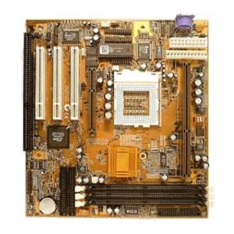
The MS7101C is a baby-AT sized mainboard that uses 4-layer printed circuit board and measures 22cm x 22cm. The mainboard features the VIA Apollo Pro Plus chipset. The MS7101C has a slot1 and a socket-370 so that it can be installed with either a slot1 processor (SEPP Celeron, Pentium-II, Pentium-III) or a socket-370 processor (PPGA Celeron). -
Page 6: About The Manual
This chapter contains the following information: ! About the Manual explains how the information in this manual is organized ! Checklist comprises a list of the standard and optional components that are shipped with this mainboard ! Recommendations lists some Do’s and Don’ts from the manufacturer to help ensure reliability and performance from this product ! Features highlights the functions and components that make this... -
Page 7: Checklist
If any item is missing or appears damaged, please contact the vendor of your mainboard package. Standard Items " " " " 1 x MS7101C Mainboard " " " " 1 x Cable/Bracket Pack Diskette drive ribbon cable IDE drive ribbon cable "... -
Page 8: Features
300 MHz through to 500 MHz. The PPGA Celeron is the ideal processor choice for an entry-level PC. For better performance, the MS7101C can be installed with a slot1 processor. The SEPP (Single Edge Processor Package) Celeron is the least expensive slot-1 processor. - Page 9 Inexpensive Memory The board has three DIMM sockets for the installation of 168-pin, 3.3V non-buffered DIMM memory modules. The DIMM memory modules must be installed with SDRAM memory chips. The board supports a memory bus of 66 MHz or 100 MHz, so you can choose between inexpensive 66 MHz memory modules or high-performance PC-100 memory modules.
- Page 10 mainboard includes connections for floppy diskette drives and two PCI IDE channels. Keyboard Power On Feature Using the system BIOS setup program, you can configure the system to turn on using a keyboard typed password. A green keyboard is not required.
-
Page 11: Chapter 2: Installation
Quick Installation Table This chapter explains how to successfully install the mainboard into a computer case and build a working system. The installation procedure is as follows: Quick Jumper Provides a quick reference for the jumper Setting Reference settings on this mainboard. Before you Begin Provides advice on choosing a case, avoiding static electricity damage, and setting... -
Page 12: Quick Jumper Setting Reference
Quick Jumper Setting Reference If you are familiar with most of the material in this chapter, you can begin preparing the mainboard for installation by using this quick reference to begin setting the jumpers. A detailed description of the jumper setting appears later in this chapter. -
Page 13: Before You Begin
Force 100 MHz Open pins 1-2 Before You Begin Before you begin to install your MS7101C mainboard, take some precautions to ensure that you avoid the possibility of damage to the product from static electricity. Ensure too that you are installing the mainboard into a suitable case. -
Page 14: Choosing A Case
Ensure that your case supports all the features required. The MS7101C mainboard can support one or two floppy diskette drives and four enhanced IDE drives. Ensure that your case has sufficient power and space for all the drives that you intend to install. -
Page 15: Preparing The Mainboard
Preparing the Mainboard Mainboard Guide Use the following illustration and key to identify the components on your mainboard. DIMM3 DIMM2 DIMM1 SLOT1 COM2 COM1 FDC1 FAN1 SOCKET-370 PRN1 FAN2 IDE2 PCI1 PCI2 PCI3 IDE1 JP1A JP1B... - Page 16 Key to Mainboard Components Component Description Slot1 Slot for Slot1 processor cartridge Socket-370 Socket for PPGA Celeron Processor Slot for AGP graphics adapter PCI 1,2,3 Three 32-bit PCI slots One 8/16-bit ISA slot DIMM 1, 2, 3 Three slots for 168-pin SDRAM memory modules FDC1 Connector for floppy disk drives IDE1, IDE2...
-
Page 17: Check The Jumper Settings
Check the Jumper Settings Check all the mainboard jumpers to ensure that the board is configured correctly. JP1A: Audio Enable/disable Jumper Use this 2-pin jumper to enable or disable the audio system integrated on this mainboard. You have to disable the audio system if you plan on using an alternate audio system on an add-in card. - Page 18 JP2: Keyboard Power On Jumper This jumper lets you use a typed-in password as a power switch to turn your system on. If you enable this property, you need to define the password or the hot keys using the setup utility. See Chapter 3. Function Jumper Cap Disable keyboard power on...
- Page 19 J8: System Bus Frequency Select Jumper When this jumper is open, it forces the mainboard to use a 100 MHz system bus, even if the processor requires a 66 MHz bus. When the jumper is short, the board automatically detects which bus frequency to use.
-
Page 20: Connecting Power, Chassis Fans, And Panel
Connecting Power, Chassis Fans, and Panel After you have installed the mainboard into the system case, connect the power cable from the case power supply unit to one of the mainboard power connectors PW1 or PW2. Connect the chassis fan (if your case has one) to the 12V power supply connectors FAN2. - Page 21 J10 Panel Connector The mainboard J10 panel connector has a standard set of switch and indicator connectors that are commonly found on ATX/AT system cases. Use the illustration below to make the correct connections to the case switches and indicators. Function Pins Speaker...
-
Page 22: Install Other Hardware
Install Other Hardware Start installing the essential hardware required to get your system started. Install the Processor This mainboard has a Slot1 processor slot and a Socket-370 processor socket. You can only install one processor however, so you must choose what kind of processor to run on this board. - Page 23 Intel SEPP Celeron SEPP stands for Single Edge Processor Package. The SEPP Celeron is similar to a Pentium-II except that it only has 128K of external cache memory. The first generation of SEPP Celerons had no external cache memory at all and ran at 266 MHz. These Celerons do not ship currently but are still supported by this mainboard.
-
Page 24: Installing A Slot1 Processor
Installing a Slot1 Processor This board has a SLOT1 processor cartridge slot. The slot must be installed with a cartridge holder that supports the processor cartridge. The cartridge holder may be already installed on your mainboard with the support brackets folded over. In this case simply pull the support brackets into the upright position. - Page 25 Install the Processor Cartridge After you have installed the cartridge holder, follow the instructions supplied with the processor cartridge to insert the cartridge into the holder. If the processor has a cooling fan, connect the power cable of the fan to the power supply connector on the mainboard FAN1. Cooling fan power cable Processor Cartridge...
-
Page 26: Installing A Socket-370 Processor
Installing a Socket-370 Processor If you have decided to install the mainboard with a PPGA Celeron processor, follow the steps below. Locate the Socket-370 and CPUFAN1 Locking lever Pin-1 corner Socket-370 FAN1 1. On the mainboard, locate the socket-370 and FAN1. 2. - Page 27 Socket-370 processor Cooling fan with heatsink/cooling power cable fan assembly Socket-370 with locking lever in FAN1 cooling fan upright position power supply The mainboard must be configured to deliver the correct clock speed and the correct system bus for the kind of processor that you have installed.
-
Page 28: Install The Memory Modules
Install the Memory Modules For this mainboard, you must use 168-pin 3.3V non-buffered Dual In-line Memory Modules (DIMMs). The memory chips must be standard or registered SDRAM (Synchronous Dynamic Random Access Memory). The memory bus can run at 66 MHz or 100 MHz. If your processor operates over a 100 MHz system bus, you must install PC-100 memory that also operates over a 100 MHz bus. -
Page 29: Install A Hard Disk Drive And Cd-Rom/Dvd
3. Push the latches on each side of the DIMM slot down. 4. Install the DIMM module into the slot and press it carefully but firmly down so that it seats correctly. The latches at either side of the slot are levered upwards and latch onto the edges of the DIMM when it is installed correctly. - Page 30 4. Plug a power cable from the case power supply unit into the power connector on the back edge of the hard disk drive. 5. When you first start up your system, go immediately to the setup utility and use the IDE Hard Disk Auto Detect feature to configure the IDE devices that you have installed.
- Page 31 Power connector IDE connector Audio connector CD-ROM/DVD drive IDE ribbon cable Hard disk drive IDE1 IDE2 CD1 & CD2 Digital Audio Input If your CD-ROM/DVD drive has a digital audio output connector, you can connect the digital audio output to the digital audio input conector on the mainboard, as an alternative to using the analog audio connectors CD1 and CD2.
-
Page 32: Installing A Floppy Diskette Drive
Installing a Floppy Diskette Drive The mainboard has a floppy diskette drive interface and it ships with a diskette drive ribbon cable that supports one or two floppy diskette drives. You can install a 5.25” drive or a 3.5” drive with various capacities. The floppy diskette drive cable has one type of connector for a 5.25”... -
Page 33: Using The Expansion Slots
Using the Expansion Slots This mainboard has three 32-bit PCI expansion slots, one legacy 8/16-bit ISA slot, and one AGP slot. PCI Slots: The PCI slots can be used to install add-in cards that have the 32-bit PCI (Peripheral Components Interconnect) edge connector. ISA Slot: The ISA slot can be used to install add-in cards that have the legacy 8/16-bit ISA (Industry Standard Architecture) edge connector. - Page 34 5. Install the edge connector of the add-in card into the expansion slot. Press down quite firmly so that you are sure that the edge connector is correctly seated in the slot. 6. Secure the metal bracket of the card in the empty slot in the system case with a screw.
-
Page 35: Add-In Card Options
Add-in Card Options The mainboard has two features that can be used if you have installed either a network adapter card or a Creative PCI sound card. J6: Wake on LAN If you have installed a network adapter (LAN adapter), you can use the cable provided with the card to plug into the J6 connector on the mainboard. -
Page 36: Install Extension Brackets And Modules
Install Extension Brackets and Modules On this mainboard many of the I/O ports must be implemented by cabling extension brackets or modules to connectors on the mainboard, and then installing the brackets or modules on the system case. Some of the extension brackets or modules are supplied with the system, others are options that can be ordered or purchased from third-party vendors. - Page 37 Line and Tel Fax/modem RJ11 sockets module fax/modem connector Serial Ports Extension Bracket If you want to have external serial ports available in your computer case, you must install the serial ports extension bracket. COM2 COM1 The serial ports extension bracket is supplied with this mainboard. 1.
- Page 38 4. Secure the bracket by driving a screw through the slot in the top of the metal bracket into the system chassis. Note: An IR port and a second serial port use the same resources, and they may use some of the resources required by a fax/modem card.
- Page 39 Audio Ports Extension Bracket If you want to have external audio ports available in your computer case, you must install the audio ports extension bracket. The audio ports extension bracket is supplied with this mainboard. It includes a 15-pin game/MIDI port, and jacks for line-in, line out, and microphone.
- Page 40 Digital Audio Extension Bracket You can purchase the 24-bit digital audio extension bracket as an option. You can use the audio SPDIF jacks to connect to digital audio devices. The digital audio extension bracket is an optional item. The digital audio extension bracket has an SPDIF-In jack, an SPDIF-Out jack, and Line-in jack.
- Page 41 ATX Form Bracket You can purchase an optional ATX form card extension bracket. The ATX form bracket extension bracket is an optional item. The ATX form extension bracket includes an infrared port, a PS/2 mouse port, and two USB (Universal Serial Bus) ports. 1.
-
Page 42: Chapter 3: Setup
About the Setup Utility This chapter explains how to use and modify the BIOS setup utility that is stored on the mainboard. The setup utility stores data about the mainboard components and the configuration of devices that are connected to it. This information is used to test and initialize components at start-up time and to make sure everything runs properly when the system is operating. - Page 43 Some options lead to tables of items that usually have a value on the right side. The value of the first item is highlighted, and you can use the cursor arrow keys to select any of the other values in the table of items. When an item is highlighted, you can change the value by pressing the PageUp or PageDown keys, or the Plus or Minus keys.
-
Page 44: How To Flash A New Bios
How to Flash a New BIOS You can install an updated BIOS for this motherboard that you can download from the manufacturer’s website. A new BIOS may provide support for new peripherals, improvements in performance or fixes to address known bugs. Install a new BIOS as follows: 1. -
Page 45: Standard Cmos Setup Option
Standard CMOS Setup Option This option displays a table of items which defines basic information about your system. Date and Time The Date and Time items show the current date and time held by your computer. If you are running a Windows OS, these items are automatically updated whenever you make changes to the Windows Date and Time Properties utility. -
Page 46: Bios & Cpu Features Setup Option
Drive A and Drive B Default: 1.44M, 3.5 in., None These items define the characteristics of any diskette drive attached to the system. You can connect one or two diskette drives. Floppy 3 Mode Support Default: Disabled Floppy 3 mode refers to a 3.5” diskette with a capacity of 1.2 MB. Floppy 3 mode is sometimes used in Japan. - Page 47 CPU Internal Core Speed Default: 233 MHz Use this item to set up the mainboard for the kind of processor that you have installed. Set this item to the rated internal clock speed of the installed processor. If you set this to Manual, you can use the two items below CPU/SDRAM Bus Frequency and CPU Core: Bus Freq.
- Page 48 Quick Power On Self Test Default: Enabled You can enable this item to shorten the power on testing and have your system start up a little faster. You might like to enable this item after you are confident that your system hardware is operating smoothly. Boot From LAN First Default: Disabled Enable this item if you want your computer to remote boot an operating system...
-
Page 49: Chipset Features Option
Report No FDD for WIN 95 Default: Yes If you are running a system with no floppy drive and using the Windows 95 OS, select Yes for this item to ensure compatibility with the Windows 95 logo certification. Video BIOS Shadow Default: Enabled This item allows the video BIOS to be copied to system memory for faster performance. - Page 50 SDRAM Cycle Length Default: 3 DRAM Clock Default: Host CLK These two items determine timing parameters for system memory. We recommend that you leave these items at the default value. Memory Hole Default: Disabled This item can be used to reserve memory space for some ISA expansion cards that require it.
-
Page 51: Power Management Setup Option
Power Management Setup Option This option displays items which let you control the system power management. Modern operating systems take care of much of the power management. This mainboard supports ACPI (advanced configuration and power interface). This system supports power-saving modes; doze mode, and suspend mode. - Page 52 Power Management Default: User Define This item acts like a master switch for the power-saving modes and hard disk timeouts. If this item is set to Max Saving, doze and suspend mode, will occur after a short timeout. If this item is set to Min Saving, doze and suspend mode will occur after a longer timeout.
- Page 53 LPT & COM Default: LPT/COM Select None, or either LPT or COM or both. If LPT and/or COM is selected, any activity on the system’s parallel port (LPT) and/or serial ports (COM) will resume the system from a power-saving mode and/or reset the power-saving mode timeout counters.
-
Page 54: Pnp/Pci Configuration Option
PNP/PCI Configuration Option This option displays a table of items that configures how PNP (Plug and Play) and PCI expansion cards operate in your system. PNP OS Installed Default: No If you install a Plug and Play operating system such as Windows 95 or 98, you can set this item to Yes. -
Page 55: Load Bios Defaults Option
CPU to PCI Write Buffer Default: Enabled PCI Dynamic Bursting Default: Enabled PCI Master 0 WS Write Default: Enabled PCI Delay Transaction Default: Enabled PCI#2 Access #1 Retry Default: Disabled All of these five items determine how the system carries out read/write operations over the PCI bus. -
Page 56: Integrated Peripherals Option
Integrated Peripherals Option This option displays a list of items which defines the operation of some peripheral items on the system’s input/output ports. OnChip IDE Channel0 Default: Enabled OnChip IDE Channel0 Default: Enabled Use these items to enable or disable the primary (channel0) and secondary (channel1) IDE channels that are integrated on this mainboard. - Page 57 IDE Primary Master UDMA Default: Auto IDE Primary Slave UDMA Default: Auto IDE Secondary Master UDMA Default: Auto IDE Secondary Slave UDMA Default: Auto Each IDE channel supports a master device and a slave device. This motherboard supports UltraDMA. UltraDMA technology provides faster access to IDE devices.
-
Page 58: Supervisor And User Password Settings
performance EPP (enhanced parallel port) or the ECP (extended capabilities port) make the appropriate changes to this item. OnChip USB Default: Enabled Use this item to enable or disable the USB ports that are integrated in this mainboard. USB Keyboard Support: Default: Disabled Enable this item if you plan on using a keyboard that operates through a USB port. -
Page 59: Save And Exit Setup Option
Save And Exit Setup Option Highlight this item and press Enter to save the changes that you have made in the setup utility and exit the setup program. When the Save and Exit dialog box appears, press Y to save and exit, or press N to return to the setup main menu. -
Page 60: Chapter 4: Software
The software for this mainboard is stored in the MS7101C folder. Note: Never try to install software from a folder that is not specified for use with your mainboard. - Page 61 ! VxD: This folder cannot be used with this mainboard. It contains AGP graphics drivers for a diiferent chipset than the one used in this system. MS7101C Folder ! AUDIO, MODEM, MONITOR: These folders are empty. A readme file directs you to an alternate location with the required software.
-
Page 62: Running The Support Cd-Rom
Running the Support CD-ROM 1. Place the disk in your CD-ROM drive. If you are running Windows with Autoplay enabled, the opening screen of the CD appears automatically. Click on READ ME to read the latest instructions. 2. Click on the item BROWSE THE CD TITLE. This uses Windows Explorer to show the contents of the support CD. -
Page 63: Cmi8X38 Folder Installation Notes
PC-Cillin Anti-Virus Utility Anti-virus software is provided for DOS, for WIN95, and WIN 98. Log on to the appropriate directory for your operating system. For DOS, copy all the files in the DOS folder to your hard disk drive. For Windows 95, log on to the Disk 1 folder and run SETUP. -
Page 64: Modem Driver And Software
Modem Driver and Software Install the Modem driver from the sub-folders for Windows 95/98 or Windows NT4.0. Windows 95/98 The modem is a plug and play device so Windows 95/98 will automatically detect the presence of your modem. When the Plug and Play wizard begins to look for modem drivers, click on the button that says Have Disk and then browse or type in the pathname to the CMI8x58\modem\win9x folder. -
Page 65: Mainboard (Ms7101C) Installation Notes
Identification of Intel Chipset Components in Device Manager To install the files, run SETUP.EXE. Mainboard (MS7101C) Installation Notes All of the sub-folders in this folder are empty, with a short README file giving directions to alternate folders for the appropriate software. -
Page 66: Appendix 1: Quick Jumper Setting Reference
Appendix 1: Quick Jumper Setting Reference JP1A: Audio enable/disable jumper Use this jumper to enable or disable the audio system integrated on the mainboard. Function Jumper Cap JP1A Enable audio Open pins 1-2 Disable audio Short pins 1-2 JP1B: Modem enable/disable jumper Use this jumper to enable or disable the modem integrated on the mainboard. - Page 67 JP5: Clear CMOS memory jumper Use this 3-pin jumper to clear all the current data stored in the CMOS memory. Function Jumper Cap Normal operation Short pins 1-2 Clear CMOS Short pins 2-3 J8: System bus frequency select jumper When this jumper is open, it forces the mainboard to use a 100 MHz system bus, even if the processor requires a 66 MHz bus.
-
Page 68: Appendix 2: Glossary
Appendix 2: Glossary Stands for Accelerated Graphics Port. The AGP interface provides direct access to main memory so that an AGP graphics adapter can store large texture files in main memory when rendering complex 3D video images. BIOS Stands for Basic Input Output System. A BIOS chip provides the basic communications between all the separate components of a modern PC CD-ROM... - Page 69 Stand for Local Area Network, that is, a collection of PCs all connected with Ethernet cables. Stands for Light Emitting Diode. LEDs are used as indicator lights on most computer systems. NTSC Stands for National Television Standards Committee/ NTSC is the television video format used principally in the USA, Japan, and Central &...
- Page 70 Stands for Read Only Memory. ROM implies that the data stored in the ROM is fixed and cannot be altered. It does need to be refreshed with an electrical currwent so the data stays intact even if the device is turned off. SDRAM Stands for Synchronous Dynamic Random Access Memory.
Need help?
Do you have a question about the MS7101C and is the answer not in the manual?
Questions and answers