Table of Contents
Advertisement
Quick Links
Safety Compliance
Federal Communications Commission (FCC)
This equipment has been tested and found to comply with the limits for a
Class B digital device, pursuant to Part 15 of the FCC Rules. These
limits are designed to provide reasonable protection against harmful
interference in a residential installation. This equipment generates, uses,
and can radiate radio frequency energy and, if not installed and used in
accordance with the instructions, may cause harmful interference to
radio communications. However there is no guarantee that interference
will not occur in a particular installation. If this equipment does cause
harmful interference to radio or television reception, which can be
determined by turning the equipment off and on, the user is encouraged
to try to correct the interference by one or more of the following
measures:
! Reorient or relocate the receiving antenna.
! Increase the separation between the equipment and the receiver.
! Connect the equipment onto an outlet on a circuit different from that
to which the receiver is connected.
! Consult the dealer or an experienced radio/TV technician for help.
Shielded interconnect cables and shielded AC power cable must be
employed with this equipment to insure compliance with the pertinent RF
emission limits governing this device. Changes or modifications not
expressly approved by the system's manufacturer could void the user's
authority to operate the equipment.
Declaration of Conformity
This device complies with part 15 of the FCC rules. Operation is subject
to the following conditions:
! This device may not cause harmful interference, and
! This device must accept any interference received, including
interference that may cause undesired operation.
Canadian Department of Communications
This class B digital apparatus meets all requirements of the Canadian
Interference-causing Equipment Regulations.
Cet appareil numérique de la classe B respecte toutes les exigences du
Réglement sur le matériel brouilieur du Canada.
Advertisement
Table of Contents

Subscribe to Our Youtube Channel
Related Manuals for MATSONIC MS7157C


Summary of Contents for MATSONIC MS7157C
-
Page 1: Canadian Department Of Communications
Safety Compliance Federal Communications Commission (FCC) This equipment has been tested and found to comply with the limits for a Class B digital device, pursuant to Part 15 of the FCC Rules. These limits are designed to provide reasonable protection against harmful interference in a residential installation. -
Page 2: Important Information
Important Information Copyright This publication, including all photographs, illustrations and software, is protected under international copyright laws, with all rights reserved. Neither this manual, nor any of the material contained herein, may be reproduced without the express written consent of the manufacturer. Disclaimer The information in this document is subject to change without notice. -
Page 3: Table Of Contents
Contents Chapter 1: Introduction ..........1 Welcome ............... 1 About the Manual ............2 Checklist................ 3 Standard Items ------------------------------------------------- 3 Optional Items -------------------------------------------------- 3 Recommendations ............3 Features ................ 4 Chapter 2: Installation ..........8 Quick Installation Table..........8 Quick Jumper Setting Reference ........9 Before You Begin ............ - Page 4 Utility Folder Installation Notes ........66 CMI8X38 Folder Installation Notes ....... 67 Audio Software------------------------------------------------- 67 Modem Driver and Software-------------------------------- 68 Peripheral Folder Installation Notes......68 VIA Folder Installation Notes......... 68 Mainboard (MS7157C) Installation Notes ..... 79 Appendix 1: Quick Jumper Setting Reference..70...
-
Page 5: Chapter 1: Introduction
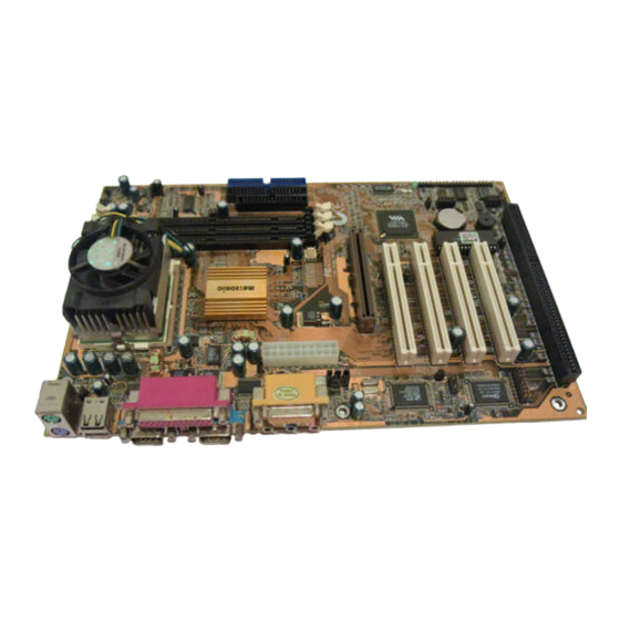
Intel Celeron or Cyrix Joshua processor, or an FC-PGA Intel Coppermine processor. The MS7157C is a full-sized ATX mainboard that uses a 4-layer printed circuit board and measures 304mm by 200mm.. The board includes a built-in sound system, 6 expansion slots including an AGP graphics slot, and a full set of I/O ports. -
Page 6: About The Manual
This chapter contains the following information: ! About the Manual explains how the information in this manual is organized ! Checklist comprises a list of the standard and optional components that are shipped with this mainboard ! Recommendations lists some Do’s and Don’ts from the manufacturer to help ensure reliability and performance from this product ! Features highlights the functions and components that make this... -
Page 7: Checklist
If any item is missing or appears damaged, please contact the vendor of your mainboard package. Standard Items " " " " 1 x MS7157C Mainboard " " " " 1 x Cable/Bracket Pack Diskette drive ribbon cable DMA 66 IDE drive ribbon cable "... -
Page 8: Features
Features The key features of this mainboard are the advanced VIA VT82C694X/ VT82C596B chipset, and the FC-PGA processor support so that you can install a wide range of Intel Celeron, Cyrix Joshua, or Intel Coppermine processors. You can use this board to develop a low-cost value system, with very comprehensive features. - Page 9 The DIMM slots support PC-100 (100 MHz) and PC-133 (133 MHz) memory modules. You can install one, two or three modules. Each memory module can hold a maximum capacity of 512 MB of standard SDRAM chips so maximum memory capacity is 1.5 GB. The VIA chipset on this board supports an asynchronous memory bus architecture, and provides option of 66/100, 100/66, 100/133 or 133/100 MHz CPU and memory bus combinations.
- Page 10 game/MIDI port. The audio system supports full duplex operation and drivers are available for WIN 95/98/2000 and WIN NT 4.0. The audio system can output sound to 4 loudspeakers and also supports SPDIF 24-bit digital sound input and output. Optional Built-in Communications The mainboard has an integrated fax/modem connector.
- Page 11 Programmable Firmware The mainboard includes Award BIOS that allows BIOS setting of CPU parameters. The fully programmable firmware enhances the system features and allows users to set power management, CPU and memory timing, LAN and modem wake-up alarms, and so on. The firmware can also be used to set parameters for different processor clock speeds so that you don’t need to change mainboard jumpers and switches.
-
Page 12: Chapter 2: Installation
Quick Installation Table This chapter explains how to successfully install the mainboard into a computer case and build a working system. The installation procedure is as follows: Quick Jumper Provides a quick reference for the jumper Setting Reference settings on this mainboard. Before you Begin Provides advice on choosing a case, avoiding static electricity damage, and setting... -
Page 13: Quick Jumper Setting Reference
Quick Jumper Setting Reference If you are familiar with most of the material in this chapter, you can begin preparing the mainboard for installation by using this quick reference to begin setting the jumpers. A detailed description of the jumper setting appears later in this chapter. - Page 14 JP9: Set System Bus Frequency to 100 MHz Use this 3-pin jumper to set the system bus frequency. In the normal setting, the system automatically selects the correct frequency according to the kind of processor installed. In the Force 100 MHz setting, the system uses a 100 MHz system bus even if the processor is designed to operate with a 66 MHz bus.
- Page 15 JP15: Automatic (BIOS) or Manual configuration Use this 3-pin jumper to automatically (BIOS) or manually set the CPU core voltage and system bus multiplier ratio. When set to manual configuration, use the VID and BF jumpers to define proper configuration. It is recommended that you set this jumper to automatic configuration.
- Page 16 Pin Settings Volt. VID0 VID1 VID2 VID3 VID4 2.8V All open All open All open All open 2.7V All open All open 2.6V All open All open All open 2.5V All open All open All open 2.4V All open All open All open All open 2.3V...
-
Page 17: Before You Begin
Before You Begin Before you begin to install your MS7157C mainboard, take some precautions to ensure that you avoid the possibility of damage to the product from static electricity. Ensure too that you are installing the mainboard into a suitable case. -
Page 18: How To Set Jumpers
The mainboard has a set of I/O ports on the rear edge. Ensure that your case has an I/O template that supports the I/O ports and expansion slots. How to Set Jumpers A jumper consists of two or more pins mounted on the mainboard. Some jumpers might be arranged in a series with each pair of pins numbered differently. -
Page 19: Preparing The Mainboard
Preparing the Mainboard Mainboard Guide Use the following illustration and key to identify the components on your mainboard. DIMM1 CPUFAN1 DIMM2 JP11 DIMM3 JP12 JP13 LED1 Socket-370 JP10 FDD1 IDE2 IDE1 ATX1 PWRFAN1 AGP1 PCI1 JP15 LED2 SPDIF1 PCI2 PCI3 PCI4 PANEL1 ISA1... - Page 20 Key to Mainboard Components Component Description SOCKET-370 Socket for Intel FC-PGA Celeron or Cyrix Joshua processor DIMM1, 2, 3 Slots for 168-pin memory modules IDE1, 2 Primary and secondary IDE channels FDD1 Connector for floppy disk drives AGP1 Slot for AGP graphics adapter PCI 1, 2, 3, 4 3 x 32-bit PCI expansion slot ISA1...
-
Page 21: I/O Ports Side View
*LED1 This red indicator turns on if your system is suspended to RAM. In a suspend to RAM, the system turns off most of the power-consuming components except for the 3.3V required to refresh the memory. If LED1 is turned on, it warns you that the computer is still active and you should not carry out any work on the mainboard. -
Page 22: Check The Jumper Settings
Check the Jumper Settings Check all the mainboard jumpers to ensure that the board is configured correctly. JP11 JP12 JP13 JP15 JP1: Clear CMOS Memory Jumper This jumper lets you erase the system setup settings that are stored in CMOS memory. You might need to erase this data if incorrect settings are preventing your system from operating. - Page 23 JP2: Keyboard Power On Jumper This jumper lets you use a typed-in password as a power switch to turn your system on. If you enable this property, you need to define the password or the hot keys using the setup utility. See Chapter 3 for more information.
- Page 24 JP9: Set System Bus Frequency to 100MHz Use this 3-pin jumper to set the system bus frequency. In the normal setting, the system automatically selects the correct frequency according to the kind of processor installed. In the Force 100 MHz setting, the system uses a 100 MHz system bus even if the processor is designed to operate with a 66 MHz bus.
- Page 25 JP15: Automatic (BIOS) or Manual configuration Use this 3-pin jumper to automatically (BIOS) or manually set the CPU core voltage and system bus multiplier ratio. When set to manual configuration, use the VID and BF jumpers to define proper configuration. It is recommended that you set this jumper to automatic configuration.
- Page 26 Pin Settings Volt. VID0 VID1 VID2 VID3 VID4 3.1V All open All open 3.0V All open All open All open 2.9V All open All open All open 2.8V All open All open All open All open 2.7V All open All open 2.6V All open All open...
-
Page 27: Install The Mainboard In The Case
Pin Settings Ratio All open All open All open All open All open All open All open *Auto: When all 1-2 pins are shorted, the system bus multiplier ratio will automatically be determined. Install the Mainboard in the Case The mainboard is drilled with a series of holes. Most system cases have mounting brackets installed in the case which correspond to the holes in the mainboard. -
Page 28: Connecting Power, Chassis Fan, And Panel
Power Supply Unit Drive Cage Template Expansion Slots Connecting Power, Chassis Fan, and Panel PWRFAN1 ATX1 PANEL1 JP16... - Page 29 After you have installed the mainboard into the system case, connect the power cable from the case power supply unit to the mainboard power connector ATX1. Connect the chassis (if your case has them) to the 12V power supply connector PWRFAN1 on the mainboard. Then connect the case switches and indicators to the PANEL1 and JP16 connector on the mainboard.
-
Page 30: Install Other Hardware
Install Other Hardware Start installing the essential hardware required to get your system started. Install the Processor This mainboard has a Socket-370 processor socket. To choose a processor, you need to consider the performance requirements of the system and also the price of the processor. Performance is based on the processor design, the clock speed and system bus frequency of the processor, and the quantity of internal cache memory and external cache memory. -
Page 31: Installing A Socket-370 Processor
Installing a Socket-370 Processor If you have decided to install the mainboard with a FC-PGA Celeron processor, follow the steps below. Locate the Socket-370 and CPUFAN1 CPUFAN1 Socket-370 Pin-1 corner Locking lever 1. On the mainboard, locate the socket-370 and CPUFAN1. 2. - Page 32 Power cable CPUFAN1 Locking lever Processor & heatsink/cooling fan assembly The mainboard must be configured to deliver the correct clock speed and the correct system bus for the kind of processor that you have installed. You can do this by either using the system setup utility, or manually, by setting the correct jumper settings on the board.
-
Page 33: Install The Memory Modules
Install the Memory Modules For this mainboard, you must use 168-pin 3.3V non-buffered Dual In-line Memory Modules (DIMMs). The memory chips must be standard or registered SDRAM (Synchronous Dynamic Random Access Memory). The memory bus can run at 100 MHz or 133 MHz. If your processor operates over a 133 MHz system bus, you must install PC-133 memory that also operates over a 133 MHz bus. -
Page 34: Install A Hard Disk Drive And Cd-Rom
Install a Hard Disk Drive and CD-ROM This section describes how to install IDE devices such as a hard disk drive and a CD-ROM drive. Note: Ribbon cable connectors are usually keyed so that they can only be installed correctly on the device connector. If the connector is not keyed make sure that you match the pin-1 side of the cable connector with the pin-1 side of the device connector. - Page 35 Installing a Hard Disk Drive 1. Install the hard disk drive into the drive cage in your system case. 2. Plug the IDE cable into the primary IDE channel on the mainboard IDE1. 3. Plug one of the connectors on the IDE cable into the IDE connector on the back edge of the hard disk drive.
- Page 36 Installing a CD-ROM Drive 1. Install the CD-ROM drive into the drive cage in your system case. 2. Plug the IDE cable into the primary IDE channel on the mainboard IDE1. 3. Plug one of the connectors on the IDE cable into the IDE connector on the back edge of the CD-ROM drive.
-
Page 37: Installing A Floppy Diskette Drive
Installing a Floppy Diskette Drive The mainboard has a floppy diskette drive interface and it ships with a diskette drive ribbon cable that supports one or two floppy diskette drives. You can install a 5.25” drive or a 3.5” drive with various capacities. The floppy diskette drive cable has one type of connector for a 5.25”... -
Page 38: Using The Expansion Slots
Using the Expansion Slots This mainboard has several expansion slots. You can install add-in cards into these slots to add new features to your system. In order to get your system started, you must install an add-in graphics adapter. The mainboard has three kinds of expansion slots. - Page 39 4. Position the edge connector of the add-in card over the expansion slot. Position the metal bracket of the card in the empty slot in the system case. 5. Install the edge connector of the add-in card into the expansion slot. Press down quite firmly so that you are sure that the edge connector is correctly seated in the slot.
-
Page 40: Add-In Card Options
Add-in Card Options The mainboard has some features that can be used by some types of add-in cards. WOL1: Wake on LAN If you have installed a network adapter (LAN adapter), you can use the cable provided with the card to plug into the WOL1 connector on the mainboard. -
Page 41: Install Options And Extension Brackets
Install Options and Extension Brackets This mainboard has a number of special connectors that allow you to add optional features to your system. You can install any of the following items: Fax/modem card option Infrared port 24-bit digital audio extension bracket (SPDIF) Fax/modem Card You must install the fax/modem card in order to use the built-in fax/modem. - Page 42 Line and Tel Fax/modem RJ11 sockets card fax/modem connector Infrared Port This option can be purchased from third-party vendors. 1. If you are installing an optional serial infrared port, connect the cable from the optional IR port to the SIR1 connector on the mainboard. SIR1 2.
- Page 43 Make the External Connections After you have installed the mainboard, make the connections to the external ports. LPT1 KBMPS2 USB1 COM1 COM2 1. KBMPS2 is a stack of two PS/2 mini-DIN ports. The upper port can be used by a PS/2 mouse or pointing device. The lower port can be used by a PS/2 keyboard.
-
Page 44: External Connector Color Coding
External Connector Color Coding To help identify the external connectors, many connectors now use standard colors as shown in the table below. Connector Color Analog VGA Blue Audio line in Light blue Audio line out Lime Digital monitor / flat panel White IEEE 1394 Grey... -
Page 45: Chapter 3: Setup
About the Setup Utility This chapter explains how to use and modify the BIOS setup utility that is stored on the mainboard. The setup utility stores data about the mainboard components and the configuration of devices that are connected to it. This information is used to test and initialize components at start-up time and to make sure everything runs properly when the system is operating. - Page 46 Some options (marked with a triangle) lead to tables of items that usually have a value on the right side. The value of the first item is highlighted, and you can use the cursor arrow keys to select any of the other values in the table of items.
-
Page 47: How To Flash A New Bios
How to Flash a New BIOS You can install an updated BIOS for this motherboard that you can download from the manufacturer’s website. New BIOS may provide support for new peripherals, improvements in performance or fixes to address known bugs. Install a new BIOS as follows: 1. -
Page 48: Standard Cmos Features Option
9. In the opening dialog box, type in the filename of the new BIOS and follow the onscreen directions to flash the new BIOS to the motherboard. 10. When the installation is complete, remove the floppy diskette from the diskette drive and restart your computer. If your mainboard has a Flash BIOS jumper, don’t forget to reset the jumper to protect the newly installed BIOS from being overwritten. - Page 49 IDE HDD Auto-Detection Press Enter while this item is highlighted if you want the setup utility to automatically detect and configure a hard disk drive on the IDE channel. IDE Primary/Secondary Master/Slave If you leave this item at Auto, the system will automatically detect and configure any IDE devices it finds.
-
Page 50: Advanced Bios Features Setup Option
Halt On Default: All Errors This item defines the operation of the system POST (Power On Self Test) routine. You can use this item to select which kind of errors in the POST are sufficient to halt the system. Base Memory, Extended Memory, Total Memory These items are automatically detected by the system at start up time. - Page 51 H/W Reset Function Default: Enabled When this item is set to disabled, the Reset button connector on the board will be disabled. CPU Internal Cache Default: Enabled All the processors that can be installed in this mainboard use internal (level 1) cache memory to improve performance.
-
Page 52: Advanced Chipset Features Option
Gate A20 Option Default: Normal This item defines how the system handles legacy software that was written for an earlier generation of processors. Leave this item at the default value. Typematic Rate Setting Default: Disabled If this item is enabled, you can use the following two items to set the typematic rate and the typematic delay settings for your keyboard. - Page 53 Bank 0/1 DRAM Timing Default: SDRAM 10ns Bank 2/3 DRAM Timing Default: SDRAM 10ns Bank 4/5 DRAM Timing Default: SDRAM 10ns This item allows you to set the speed of the memory used in the DIMM slots. SDRAM Cycle Length Default: 3 This item controls how often the data in memory will be accessed.
- Page 54 AGP Aperture Size (MB) Default: 64 MB This item defines the size of the aperture if you use an AGP graphics adapter. It refers to a section of the PCI memory address range used for graphics memory. We recommend that you leave this item at the default value. AGP 4X Mode Default: Enabled This item allows you to improve video performance by quadrupling the speed of...
-
Page 55: Integrated Peripherals Option
Data Drive (MD,WE#) Default: 6mA Command (SRAS#,SCA#,SWE#) Default: 16mA Address Drive (MA,WE#) Default: 16mA CAS# Drive Default: 8mA RAS# Drive Default: 16mA These items allow you to alter the access speeds of the different memory bus functions. These items are normally optimally determined by the system’s hardware and chipset, so we recommend that you leave these items at the manufacturers default. - Page 56 IDE Primary Master PIO Default: Auto IDE Primary Slave PIO Default: Auto IDE Secondary Master PIO Default: Auto IDE Secondary Slave PIO Default: Auto Each IDE channel supports a master device and a slave device. These four items let you assign which kind of PIO (Programmed Input/Output) is used by IDE devices.
- Page 57 Onboard FDC Controller Default: Enabled Use this item to turn on or off the floppy disk controller that is built into this mainboard. Onboard Serial Port 1 Default: 3F8/IRQ4 This item lets you disable the built-in serial port 1, or enable it by assigning an I/O address and an Interrupt Request Line (IRQ).
-
Page 58: Power Management Setup Option
Power Management Setup Option This option displays items that let you control the system power management. Modern operating systems take care of much of the power management. This mainboard supports ACPI (advanced configuration and power interface). The system has various power saving modes including powering down the hard disk, turning off the video, suspending to RAM, and a software power down that allows the system to be automatically resumed by certain events. - Page 59 Power Management Press Enter to display the Power Management sub-menu. Power Management Default: User Define This item acts like a master switch for the power-saving modes and hard disk timeouts. If this item is set to Max Saving, power-saving modes occur after a short timeout.
- Page 60 PM Control by APM Default: Yes Windows 95 and 98 have built-in power management capabilities called APM (Advanced Power Management). When you enable this item, you allow the APM routines in Windows to operate your system. Default: Suspend → Off Video Off Option This option defines how and when the video is powered down if the system is put into suspend mode.
- Page 61 Default: OFF When this item is enabled, the system will restart the power-saving timeout counters when any activity is detected on the video graphics system. LPT & COM Default: LPT/COM When this item is enabled, the system will restart the power-saving timeout counters when any activity is detected on the serial ports,or the parallel port.
- Page 62 When these item are enabled, the system will restart the timeout counters when any activity is detected on the selected Interrupt request lines. When the Primary INTR item is set to OFF, then the interrupts have no effect on system power management Press Esc to close the the IRQ Activity Monitoring sub-menu and return to the Wake Up Events page.
-
Page 63: Pnp/Pci Configuration Option
PNP/PCI Configuration Option This option displays a table of items that configures how PNP (Plug and Play) and PCI expansion cards operate in your system. PNP OS Installed Default: No If you have installed a Plug and Play operating system, such as Windows 95 or 98, you can change this item to Yes. -
Page 64: Pci Health Status Option
PCI/VGA Palette Snoop Default: Disabled This item is designed to overcome some problems that can be caused by some non-standard VGA cards. This board includes a built-in VGA system that does not require palette snooping so you must leave this item disabled. Assign IRQ For VGA Default: Enabled Assign IRQ For USB... -
Page 65: Frequency / Voltage Control Option
Frequency / Voltage Control Option This item allows you to set the clock speed and system bus for your system. The clock speed and system bus are determined by the kind of processor you have installed in your system. Auto Detect DIMM/PCI Clk Default: Enabled When this item is enabled, the BIOS will disable the clock generator signal for unused DIMM and PCI slots, in order to reduce EMI (electromagnetic intererence) -
Page 66: Load Fail-Safe Defaults Option
CPU clock failed reset Default: Disabled If this item is enabled, and your system crashes three times because you have overclocked the processor, this item will automatically adjust the speed of the processor to the system bus speed multiplied by two. CPU Voltage Default: Auto The onboard hardware monitor is able to automatically detect the voltage output... -
Page 67: Save And Exit Setup Option
3. If you are installing a new password, carefully type in the password. You cannot use more than 8 characters or numbers. The password will differentiate between upper case and lower characters. Press Enter after you have typed in the password. If you are deleting a password that is already installed just press Enter when the password dialog box appears. -
Page 68: Chapter 4: Software
INTEL and VIA folders. In addition, software that is specifically intended for one kind of mainboard is stored in a folder with the name of that board. The software for this mainboard is stored in the MS7157C folder. Note: Never try to install software from a folder that is not specified for use with your mainboard. - Page 69 Windows 9x. ! Win NT: This folder contains the IDE driver update for use with Windows NT. MS7157C Folder ! AUDIO, MODEM: These folders are empty. A readme file directs you to an alternate location with the required software. Note: Some folders are subdivided into different operating systems such as DOS, Windows 95, Windows NT, and so on.
-
Page 70: Running The Support Cd-Rom
Running the Support CD-ROM 1. Place the disk in your CD-ROM drive. If you are running Windows with Autoplay enabled, the opening screen of the CD appears automatically. Click on READ ME to read the latest instructions. 2. Before installing the software, look for a file named README.TXT, or something similar. -
Page 71: Cmi8X38 Folder Installation Notes
MediaRing Talk To install the MediaRing Talk voice modem software for the built-in modem, run MRTALK99-SETUP. PC-Cillin Anti-Virus Utility Anti-virus software is provided for DOS, for WIN95, and WIN 98. Log on to the appropriate directory for your operating system. For DOS, copy all the files in the DOS folder to your hard disk drive. -
Page 72: Modem Driver And Software
8. Select "C-A+dia PCI Device" and press the "OK" button. 9. Choose proper I/O or the "OK" button for the default setting. 10. Restart the Windows NT system. To install the audio applications, log on to the NT4 folder, and then log on to the APPS folder. -
Page 73: Mainboard (Ms7157C) Installation Notes
Run the "setup" program from the VIA directory to install the IDE driver updates for use with Windows NT. Mainboard (MS7157C) Installation Notes All of the sub-folders in this folder are empty, with a short README file giving directions to alternate folders for the appropriate software. -
Page 74: Appendix 1: Quick Jumper Setting Reference
Appendix 1: Quick Jumper Setting Reference JP1: Clear CMOS memory jumper Use this 3-pin jumper to clear all the current data stored in the CMOS memory. Function Jumper Cap Normal operation Short pins 1-2 1 2 3 Clear CMOS Short pins 2-3 JP2: Keyboard power on jumper Use this 3-pin jumper to enable keyboard power on with hot keys or password. - Page 75 JP9: Set System Bus Frequency to 100 MHz Use this 3-pin jumper to set the system bus frequency. In the normal setting, the system automatically selects the correct frequency according to the kind of processor installed. In the Force 100 MHz setting, the system uses a 100 MHz system bus even if the processor is designed to operate with a 66 MHz bus.
- Page 76 JP15: Automatic (BIOS) or Manual configuration Use this 3-pin jumper to automatically (BIOS) or manually set the CPU core voltage and system bus multiplier ratio. When set to manual configuration, use the VID and BF jumpers to define proper configuration. It is recommended that you set this jumper to automatic configuration.
- Page 77 Pin Settings Volt. VID0 VID1 VID2 VID3 VID4 2.8V All open All open All open All open 2.7V All open All open 2.6V All open All open All open 2.5V All open All open All open 2.4V All open All open All open All open 2.3V...
Need help?
Do you have a question about the MS7157C and is the answer not in the manual?
Questions and answers