Table of Contents
Advertisement
Quick Links
Important Information
Copyright
This publication, including all photographs, illustrations and software, is
protected under international copyright laws, with all rights reserved.
Neither this manual, nor any of the material contained herein, may be
reproduced without the express written consent of the manufacturer.
Disclaimer
The information in this document is subject to change without notice. The
manufacturer makes no representations or warranties with respect to the
contents hereof and specifically disclaims any implied warranties of
merchantability or fitness for any particular purpose. Further, the
manufacturer reserves the right to revise this publication and to make
changes from time to time in the content hereof without obligation of the
manufacturer to notify any person of such revision or changes.
Trademark Recognition
Microsoft, MS-DOS and Windows are registered trademarks of Microsoft
Corp.
MMX, Pentium, Pentium-II, Pentium-III, Celeron are registered
trademarks of Intel Corporation.
VGA, OS/2, PS/2 are registered trademarks of International Business
Machines.
AMD, K5, K6 are registered trademarks of Advanced Micro Devices Inc.
Cyrix, M1 are registered trademarks of Cyrix Corporation.
Other product names used in this manual are the properties of their
respective owners and are acknowledged.
Version 3.0
Advertisement
Table of Contents

Related Manuals for MATSONIC MS7102C


Summary of Contents for MATSONIC MS7102C
-
Page 1: Important Information
Important Information Copyright This publication, including all photographs, illustrations and software, is protected under international copyright laws, with all rights reserved. Neither this manual, nor any of the material contained herein, may be reproduced without the express written consent of the manufacturer. Disclaimer The information in this document is subject to change without notice. -
Page 2: Canadian Department Of Communications
Safety Compliance Federal Communications Commission (FCC) This equipment has been tested and found to comply with the limits for a Class B digital device, pursuant to Part 15 of the FCC Rules. These limits are designed to provide reasonable protection against harmful interference in a residential installation. -
Page 3: Table Of Contents
Contents Chapter 1: Introduction Welcome ............... 1 About the Manual ............2 Checklist................ 2 Features ................ 3 Chapter 2: Installation Before You Begin ............6 Mainboard Guide............7 I/O Ports Side View ............8 Preparing the Mainboard..........9 Install the Mainboard in the System Case ....17 Make the External Connections ........ -
Page 4: Chapter 1: Introduction
Intel Pentium-II/III processor. The MS7102C is a full-sized ATX board measuring 305x220mm and using 4-layer printed circuit board. The MS7102C has a special design feature so that it includes a Pentium- II Slot-1 processor slot and a PPGA (Plastic Pin Grid Array) Celeron Socket-PGA370 processor socket. -
Page 5: About The Manual
If any item is missing or appears damaged, please contact the vendor of your mainboard package. Standard Items " " " " 1 x MS7102C Mainboard " " " " 1 x Cable/Bracket Pack Diskette drive ribbon cable IDE drive ribbon cable "... -
Page 6: Features
Features The key feature of this mainboard is the dual processor sockets which allow you to install any of the Pentium-III and Pentium-II processors including Slot1 cartridges SEPP Celerons and PPGA Celerons. In addition, this is a full-sized ATX mainboard with a full set of expansion slots for maximum development potential. - Page 7 Choice of Memory Options The board has three DIMM slots for the installation of 168-pin, 3.3V standard or registered SDRAM (Synchronous Dynamic Random Access Memory) memory modules. The system supports memory that has built- in error correction (EC), error correction code (ECC), or has no error correction.
- Page 8 line and telephone RJII sockets to the board. The fax/modem supports the V.90 protocol that allows transmissions at up to 56Kbps and is fully compatible with earlier transmission and error correction standards. It supports automatic fall back and caller ID. Maximum Expansion Options This is a full-sized ATX mainboard that offers the maximum in system expansion.
-
Page 9: Chapter 2: Installation
Before You Begin Before you begin to install your MS7102C mainboard, take some precautions to ensure that you avoid the possibility of damage to the product from static electricity. Ensure too that you are installing the mainboard into a suitable case. -
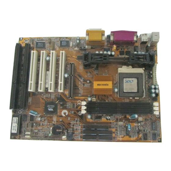
Page 10: Mainboard Guide
enhanced IDE drives. Ensure that your case has sufficient power and space for all the drives that you intend to install. The mainboard has a set of I/O ports on the rear edge. Ensure that your case has an I/O template that supports the I/O ports and expansion slots. Mainboard Guide Use the following illustration and key to identify the components on your mainboard. - Page 11 Key to Mainboard Components Component Description ISA1,2 2 x 8/16-bit ISA expansion slots AGP1 AGP graphics adapter slot PCI 1,2,3,4 4 x 32-bit PCI expansion slots SOCKET PGA370 Processor socket for PPGA Celeron processor SLOT1 Slot for Pentium-II/III processor or SEPP Celeron processor DIMM1,2,3 Slots for 168-pin memory modules FDD1...
-
Page 12: I/O Ports Side View
I/O Ports Side View LPT1 KBMPS2 USB1 COM1 COM2 Key to I/O Ports Component Description KBMPS2 PS/2 port for pointing device (upper port) PS/2 port for keyboard (lower port) LPT1 External parallel port JS1 (Upper) External game/MIDI port JS1 (Lower) Audio jacks for (left to right) line out, line in, microphone COM2 External monitor port... - Page 13 Installing a SLOT1 Cartridge Holder and Cartridge The SLOT1 on the mainboard must be installed with a retention mechanism to support the cartridge. The illustrations below show how to install several different kinds of Slot1 cartridge holders. Captive nut Cartridge holder This cartridge holder is in one Slot1 piece.
- Page 14 Some cartridge holders also include a support bar for the processor heat sink. This bar installs to the side of the cartridge holder. Some processor cartridges have support struts for the heat sink which lock into the support bar. The documentation supplied with the processor shows hot to do this.
-
Page 15: Install The Memory Modules
5. Swing the locking lever down and hook it under the latch on the side of the socket to lock it in place. 6. Locate the power connector for the processor cooling fan CPU FAN1. If your processer has a cooling fan installed, connect the cable from the cooling fan to CPU FAN1. - Page 16 2. The DIMM slots are keyed with notches and the DIMMs are keyed with cut-outs so that they can only be installed correctly. Check that the cut-outs on the DIMM module edge connector match the notches in the DIMM slot. 3.
- Page 17 J P 2 J P 4 J P 1 J P 7 JP1: Clear CMOS Memory Jumper This jumper lets you erase the system setup settings that are stored in CMOS memory. You might need to erase this data if incorrect settings are preventing your system from operating.
- Page 18 JP4: System Bus Frequency Select Jumper Use this jumper to select a system bus frequency of either Normal or 100 MHz. If Normal, the system automatically selects 66 or 100 MHz, according to the installed processor. If 100 MHz, the system will force a system bus of 100 MHz no matter what kind of processor is installed.
- Page 19 J1: Fax/modem Extension Bracket The fax/modem extension bracket is supplied with this mainboard. 1. Locate the J1 fax/modem connector on the mainboard. 2. Remove the expansion slot blanking plate from the system chassis that is adjacent to the fax/modem connector. 3.
-
Page 20: Install The Mainboard In The System Case
Install the Mainboard in the System Case Use the screws and mounting brackets supplied with your system case to install the mainboard. Follow the instructions provided by the case manufacturer. Connect Devices, Switches and Indicators Note: You might not need to carry out every step in the following procedure. - Page 21 devices. If you connect two devices, you must configure one device as Master, and one device as Slave. See the documentation provided with the devices for information on this. To install more drives, use another IDE cable and connect one or two devices to IDE2.
- Page 22 Audio Connectors & Infrared Connector SPDIF1 SIR1 1. If you want to install an optional Serial Infrared Port, connect the cable from the optional IR port to the SIR1 connector on the mainboard. Note: An infrared port (SIR1) and a second serial port (COM2) share the same resources.
- Page 23 Expansion Slots You can use the expansion slots to install expansion boards that add new features to your system. You must install a graphics adapter in order to use the system. AGP1 PCI1 PCI2 PCI3 PCI4 ISA1 ISA2 1. The AGP slot can be used by a graphics adapter with an AGP edge connector.
- Page 24 Wake-Up Connectors and SB-Link SIDEBAND1 WOL1 WOM1 4. The mainboard has wake up connectors for an optional network adapter or an optional internal fax/modem card. If you have installed a network adapter expansion card, connect it to the wake on LAN connector WOL1.
-
Page 25: Make The External Connections
Make the External Connections After you have installed the mainboard, make the connections to the external ports. LPT1 KBMPS2 USB1 COM1 COM2 1. KBMPS2 is a stack of two PS/2 mini-DIN ports. The upper port can be used by a PS/2 mouse or pointing device. The lower port can be used by a PS/2 keyboard. -
Page 26: Chapter 3: Setup
About the Setup Utility This chapter explains how to use and modify the BIOS setup utility that is stored on the mainboard. The setup utility stores information about the mainboard components, and the configuration of other devices that are connected to it. The system uses this information to test and initialize components when it is started up, and to make sure everything runs properly when the system is operating. - Page 27 Some options lead to dialog boxes which ask you verify that that you wish to execute that option. You usually answer these dialogs by typing Y for yes and N for no. Some options lead to dialog boxes which ask for more information. Setting the User Password or Supervisor Password have this kind of dialog box.
-
Page 28: Standard Cmos Setup Option
When you are in one of the options that displays a table of items, you can return to the main menu by pressing the Escape key. For some items, you can display a help message by pressing the F1 key. You can change the color scheme of the utility by pressing the F2 key while holding down the Shift key. -
Page 29: Bios Feature Setup Option
Hard Disks Defaults: Auto These items show the characteristics of any hard disk drives on the four available IDE channels. (Note that SCSI hard disk drives do not appear here.) You can automatically install most modern hard disks using the IDE HDD Auto Detect Option from the main menu. - Page 30 CPU Internal Core Speed Default: 350MHz This item should be installed with the rated internal core speed of the Pentium-II class processor that is installed in your system. The setup utility will then automatically configure the system with the correct host bus speed, and bus frequency multiplier.
- Page 31 CIH Buster Protection Default: Enabled Anti-Virus Protection Default: Enabled When “CIH Buster Protection” item is enabled it provided some protection against viruses which try to destroy BIOS viruses (especially for CIH). When “Anti-Virus Protection” item is enabled it provides some protection against viruses which try to write to the boot sector and partition table of your hard disk drive.
-
Page 32: Chipset Features Option
Boot Up NumLock Status Default: On This item defines if the keyboard Num Lock key is active when your system is started. Gate A20 Option Default: Normal This option provides compatibility with older software written for the 286 processor. Leave this item at the default value Normal. Memory Parity/ECC Check Default: Disabled This mainboard supports memory modules that have error checking using a... - Page 33 specifications of your hardware. If you change the values, you may introduce fatal errors or recurring instability into your system. Bank 0/1 DRAM Timing Default: SDRAM 10ns Bank 2/3 DRAM Timing Default: SDRAM 10ns Bank 4/5 DRAM Timing Default: SDRAM 10ns These items define the timing parameters for the system memory.
-
Page 34: Power Management Setup Option
System BIOS Cacheable Default: Enabled Video BIOS Cacheable Default: Disabled These items allow the video and/or system to be cached in memory for faster execution. Wee recommend that you leave these items at the default value. Video RAM Cacheable Default: Disabled This item permits the video memory to be cached for faster performance. - Page 35 much of the routine power management. This mainboard supports ACPI (advanced configuration and power interface). This system supports three levels of power-saving modes; doze mode, standby mode, and suspend mode. Standby mode uses less power than doze mode and suspend mode uses the least power. The power management in the setup utility lets you specify a timeout for each of the power-saving modes, and a timeout for a hard disk drive power down.
- Page 36 PM Control by APM Default: Yes Windows 95 and 98 have built-in power management capabilities called APM (advanced power management). When you enable this item, you allow the APM routines in Windows to operate on your system. Video Off Option Default: Suspend ->...
-
Page 37: Pnp/Pci Configuration Option
HDD & FDD Default: ON When this item is enabled, it defines system activities which can reset power- saving mode timeouts to zero, or resume the system from a power saving mode. This item is for hard disk and/or diskette drive activity. DMA/master Default: OFF When this item is enabled, it defines system activities which can reset power-... - Page 38 PNP OS Installed Default: No If you have installed a Plug and Play operating system such as Windows 95 or 98, you can change this item to Yes. When the item is set to Yes you can use the Device Manager utility in the operating system to make changes to the configuration of expansion cards.
-
Page 39: Load Bios Defaults Option
Load BIOS Defaults Option This option displays a dialog box which allows you to install BIOS defaults for all appropriate items in the whole setup utility. Press the Y key and then the Enter key to install the defaults. Press the N key and then Enter to not install the defaults. - Page 40 OnChip IDE Channel0 Default: Enabled OnChip IDE Channel1 Default: Enabled You can use these items to enable or disable the primary (0) and secondary (1) IDE channels that are built into this mainboard. When one or both channels are enabled, items appear which allow you to set the PIO (programmable input/output) mode and the UltraDMA mode for master and slave devices on the channels.
- Page 41 IDE Primary Master UDMA Default: Auto IDE Primary Slave UDMA Default: Auto IDE Secondary Master UDMA Default: Auto IDE Secondary Slave UDMA Default: Auto Each IDE channel supports a master device and a slave device. This motherboard supports UltraDMA. UltraDMA technology provides faster access to IDE devices.
-
Page 42: Supervisor And User Password Settings
infrared port. See the documentation for the infrared port for information on these items. Onboard Parallel Port Default: 378/IRQ7 This item lets you disable the built-in parallel port, or enable it by assigning an I/O address and an Interrupt Request Line (IRQ). Parallel Port Mode Default: ECP + EPP This item defines the operation of the parallel port. -
Page 43: Ide Hdd Auto Detection Option
IDE HDD Auto Detection Option This item automatically detects and installs any hard disk drives installed on the primary and secondary IDE channel. Most modern drives can be detected. If you are using a very old drive that can’t be detected, you can install it manually using the Standard CMOS Setup option. -
Page 44: Chapter 4: Software
The folder for this mainboard is stored in the MS7102C folder. Note: Never try to install software from a folder that is not specified for use with your mainboard. - Page 45 ! USB_UPDATE: This driver updates Windows 95 to support USB. ! VxD: The VxD driver provides support for an AGP graphics adapter. MS7102C Folder You can use the software in the following sub-folders: ! AUDIO, MODEM: These folders are empty. A readme file directs you to alternate location with the required software.
-
Page 46: Running The Support Cd-Rom
Running the Support CD-ROM 1. Place the disk in your CD-ROM drive. If you are running Windows with Autoplay enabled, the opening screen of the CD appears automatically. Click on READ ME to read the latest instructions. 2. Click on the item BROWSE THE CD TITLE. This uses Windows Explorer to show the contents of the support CD. -
Page 47: Cmi8338 Audio Folder Installation Note
PC-Cillin Anti-Virus Utility Anti-virus software is provided for DOS, for WIN95, and WIN 98. Log on to the appropriate directory for your operating system. For DOS, copy all the files in the DOS folder to your hard disk drive. For Windows 95, log on to the Disk 1 folder and run SETUP. -
Page 48: Via Folder Installation Note
Modem Driver and Software 1. In the BIOS system setup utility 2. In the “Chipset Features Setup” of the system setup utility 3. Enable the item “On Board Modem” Install the Modem driver from the sub-folders for Windows 95/98 or Windows NT4.0. - Page 49 Windows NT Installation 1. Carry out the installation instructions for Windows 95/98 steps 1 to 4. 2. In the Control Panel, select the icon SCSI adapters. 3. Select the Add button on the drivers sheet. 4. Select the item “VIA Bus Master PCI IDE Driver” and click OK. 5.
-
Page 50: Mainboard Installation Notes
2. Browse to the correct folder and select the program called SETUP.EXE. Follow the instructions on the screen to complete the installation. Mainboard (MS7102C) Installation Notes Most of the sub-folders in this folder are empty, with a short README file giving directions to alternate folders for the appropriate software. Two folders contain software that you can install. -
Page 51: Appendix 1: Quick Jumper Setting Reference
Appendix 1: Quick Jumper Setting Reference JP1: Clear CMOS Memory Jumper Use this 3-pin jumper to clear the contents of the CMOS memory. Function Jumper Cap Normal Operation Short pins 1-2 Clear CMOS Short pins 2-3 JP2: Keyboard Power On Jumper Use this 3-pin jumper to enable a keyboard power on. - Page 52 PANEL: Case Switches and Indicators Use the Panel connector to implement the switches and indicators on the system case. PANEL Function Pins Power SW 22-23 Power Indicator 1+, 2+, 3 HDD LED 20-21 Sleep Switch 4, 5 Green Indicator 7+, 8+, 9 Speaker 15-16-17-18 Keylock 10, 11...
Need help?
Do you have a question about the MS7102C and is the answer not in the manual?
Questions and answers