
Related Manuals for Intel S2600CO series


Summary of Contents for Intel S2600CO series
- Page 1 Intel Server Board S2600CO Family ® Technical Product Specification Intel order number G42278-004 Revision 1.4 September, 2013 Enterprise Platforms and Services Division – Marketing...
-
Page 2: Revision History
Information in this document is provided in connection with Intel products. No license, express or implied, by ® estoppel or otherwise, to any intellectual property rights is granted by this document. Except as provided in Intel ® ® Terms and Conditions of Sale for such products, Intel... -
Page 3: Table Of Contents
Intel® Server Board S2600CO Family TPS Table of Contents Table of Contents 1. Introduction ..........................1 1.1 Chapter Outline ......................1 1.2 Server Board Use Disclaimer ..................2 2. Product Overview ........................3 2.1 Server Board Connector and Component Layout ............ 5 ... - Page 4 Table of Contents Intel® Server Board S2600CO Family TPS 6.1 Baseboard Management Controller (BMC) Firmware Feature Support ....52 6.1.1 IPMI 2.0 Features ....................52 6.1.2 Non IPMI Features ....................53 6.1.3 New Manageability Features .................. 54 6.2 Advanced Configuration and Power Interface (ACPI) ..........55 ...
- Page 5 Intel® Server Board S2600CO Family TPS Table of Contents 7.2.1 Availability ........................ 81 7.2.2 Network Port Usage ....................81 8. On-board Connector/Header Overview ................82 8.1 Power Connectors ....................82 8.1.1 Main Power ......................82 8.1.2 CPU Power Connectors ..................82 ...
- Page 6 Table of Contents Intel® Server Board S2600CO Family TPS 9.2 Integrated BMC Force Update Procedure .............. 97 9.3 ME Force Update Jumper ..................97 9.4 BIOS Recovery Jumper ..................98 10. Light Guided Diagnostics ....................99 10.1 5 Volt Stand-by LED ....................99 ...
- Page 7 Intel® Server Board S2600CO Family TPS List of Figures List of Figures Figure 1. Major Board Components ....................6 ® Figure 2. Intel Light Guided Diagnostic LED Identification ............7 Figure 3. Jumper Block Identification ..................... 8 Figure 4. Rear I/O Layout ....................... 9 ...
-
Page 8: List Of Tables
List of Tables Intel® Server Board S2600CO Family TPS List of Tables ® Table 1. Intel Server Board S2600CO Family Feature Set ............3 Table 2. Mixed Processor Configurations Error Summary ............18 Table 3. UDIMM Support Guidelines .................... 22 ... - Page 9 Intel® Server Board S2600CO Family TPS List of Tables Table 40. RMM4_Lite Connector Pin-out (RMM4_Lite) ............... 90 Table 41. RMM4_NIC Connector Pin-out (RMM4_NIC) .............. 90 Table 42. TPM Connector Pin-out (TPM) ..................90 Table 43. PMBus* Connector Pin-out (SMB_PMBUS*) .............. 91 ...
- Page 10 List of Tables Intel® Server Board S2600CO Family TPS Table 81. Integrated BMC Beep Codes ..................151 Revision 1.4 Intel order number G42278-004...
- Page 11 Intel® Server Board S2600CO Family TPS List of Tables <This page is intentionally left blank.> Revision 1.4 Intel order number G42278-004...
-
Page 13: Introduction
Introduction This Technical Product Specification (TPS) provides board-specific information detailing the ® features, functionality, and high-level architecture of the Intel Server Board S2600CO. Design-level information related to specific server board components and subsystems can be obtained by ordering External Product Specifications (EPS) or External Design Specifications (EDS) related to this server generation. -
Page 14: Server Board Use Disclaimer
Introduction Intel® Server Board S2600CO Family TPS Server Board Use Disclaimer Intel Corporation server boards support add-in peripherals and contain a number of high-density VLSI (Very Large Scale Integration) and power delivery components that need adequate airflow ® ® to cool. Intel... -
Page 15: Product Overview
Server Board S2600CO is a monolithic printed circuit board (PCB) assembly with features designed to support the pedestal server markets. It has two board SKUs, namely ® ® S2600CO4 and S2600COE. These server boards are designed to support the Intel Xeon ® ®... -
Page 16: Intel Order Number G42278
Support up to six expansion slots ® Slot 1: PCIe Gen II x4 electrical with x8 physical connector, routed from Intel C600 Chipset, support half-length card Slot 2: PCIe Gen III x16 electrical with x16 physical connector, routed from CPU1, support full length card ... -
Page 17: Server Board Connector And Component Layout
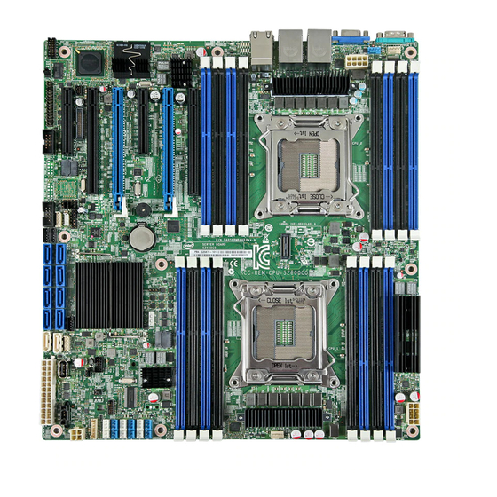
Intel® Server Board S2600CO Family TPS Product Overview Server Board Connector and Component Layout The following illustrations provide a general overview of the server board, identifying key feature and component locations. Each connector and major component is identified by a number or letter, and the description is given below the figure. -
Page 18: Figure 1. Major Board Components
Product Overview Intel® Server Board S2600CO Family TPS Callout Description Callout Description double width card Battery Main Power USB_4 (Internal Type A USB Slot 4, PCI Express* Gen3 Connector) Slot 5, PCI Express* Gen3 (blue slot), supports Storage Upgrade key connector double width card ®... -
Page 19: Figure 2. Intel Light Guided Diagnostic Led Identification
Intel® Server Board S2600CO Family TPS Product Overview ® Figure 2. Intel Light Guided Diagnostic LED Identification See Chapter 10 for additional details. Revision 1.4 Intel order number G42278-004... -
Page 20: Figure 3. Jumper Block Identification
Product Overview Intel® Server Board S2600CO Family TPS Figure 3. Jumper Block Identification See Chapter 9 for additional details. Revision 1.4 Intel order number G42278-004... -
Page 21: Figure 4. Rear I/O Layout
Intel® Server Board S2600CO Family TPS Product Overview Callout Description Callout Description Serial Port A NIC Port 3 and 4 Video Diagnostics LED’s NIC Port 1, USB Port 0 (top) and 1 ID LED (bottom) NIC Port 2, USB Port 2 (top) and 3... -
Page 22: Server Board Dimensional Mechanical Drawings
Product Overview Intel® Server Board S2600CO Family TPS Server Board Dimensional Mechanical Drawings Figure 5. Mounting Hole Locations (1 of 2) Revision 1.4 Intel order number G42278-004... -
Page 23: Figure 6. Mounting Hole Locations (2 Of 2)
Intel® Server Board S2600CO Family TPS Product Overview Figure 6. Mounting Hole Locations (2 of 2) Revision 1.4 Intel order number G42278-004... -
Page 24: Figure 7. Major Connector Pin-1 Locations
Product Overview Intel® Server Board S2600CO Family TPS Figure 7. Major Connector Pin-1 Locations Revision 1.4 Intel order number G42278-004... -
Page 25: Figure 8. Primary Side Keep-Out
Intel® Server Board S2600CO Family TPS Product Overview Figure 8. Primary Side Keep-out Revision 1.4 Intel order number G42278-004... -
Page 26: Figure 9. Secondary Side Keep-Out
Product Overview Intel® Server Board S2600CO Family TPS Figure 9. Secondary Side Keep-out Revision 1.4 Intel order number G42278-004... -
Page 27: Functional Architecture Overview
Intel® Server Board S2600CO Family TPS Functional Architecture Overview Functional Architecture Overview ® The architecture and design of the Intel Server Board S2600CO is developed around the ® integrated features and functions of the Intel processor E5-2600 or E5-2600 v2 product family, ®... -
Page 28: Processor Support
Figure 11. Processor Socket Assembly 3.1.2 Processor Population Rules Note: Although the server board does support dual-processor configurations consisting of ® different processors that meet the defined criteria below, Intel does not perform validation Revision 1.4 Intel order number G42278-004... -
Page 29: Processor Initializion Error Summary
Processor stepping within a common processor family can be mixed as long as it is listed in the processor specification updates published by Intel Corporation. 3.1.3 Processor Initializion Error Summary The following table describes mixed processor conditions and recommended actions for all ®... -
Page 30: Table 2. Mixed Processor Configurations Error Summary
Functional Architecture Overview Intel® Server Board S2600CO Family TPS Minor: The message is displayed on the screen or on the Error Manager screen, and the POST Error Code is logged to the SEL. The system continues booting in a degraded state. -
Page 31: Processor Function Overview
The following sections will provide an overview of the key processor features and functions that help to define the architecture, performance and supported functionality of the server board. For ® ® more comprehensive processor specific information, refer to the Intel Xeon processor E5- 2600 or E5-2600 v2 product family documents listed in the Reference Documents list. -
Page 32: Intel Quickpath Interconnect
Functional Architecture Overview Intel® Server Board S2600CO Family TPS Processor Core Features: Up to twelve execution cores ® Each core supports two threads (Intel Hyper-Threading Technology), up to 16 threads per socket 46-bit physical addressing and 48-bit virtual addressing ... -
Page 33: Integrated Memory Controller (Imc) And Memory Subsystem
Intel® Server Board S2600CO Family TPS Functional Architecture Overview ® The Intel QuickPath Interconnect includes a cache coherency protocol to keep the distributed memory and caching structures coherent during system operation. It supports both low-latency source snooping and a scalable home snoop behavior. The coherency protocol provides for direct cache-to-cache transfers for optimal latency. -
Page 34: Table 3. Udimm Support Guidelines
Functional Architecture Overview Intel® Server Board S2600CO Family TPS o Demand and Patrol Scrubbing o DRAM Single Device Data Correction (SDDC) for any single x4 or x8 DRAM device. Independent channel mode supports x4 SDDC. x8 SDDC requires lockstep mode... -
Page 35: Table 5. Lrdimm Support Guidelines
Intel® Server Board S2600CO Family TPS Functional Architecture Overview 1066, 1333, 1066, 1333, 1066,1333 SRx8 1066, 1333 1600 1600 1066, 1333, 1066, 1333, 1066,1333 DRx8 1066, 1333 1600 1600 1066, 1333, 1066, 1333, 1066,1333 SRx4 1066, 1333 1600 1600 1066, 1333,... -
Page 36: Table 6. Intel ® Server Board S2600Co Dimm Nomenclature
DIMMs installed. ® Each installed processor provides four channels of memory. On the Intel Server Board S2600CO each memory channel support 2 memory slots, for a total possible 16 DIMMs installed. -
Page 37: Figure 13. Intel ® Server Board S2600Co Dimm Slot Layout
Mixing of LRDIMM with any other DIMM type is not allowed per platform. ® Mixing of DDR3 voltages is not validated within a socket or across sockets by Intel . If 1.35V (DDR3L) and 1.50V (DDR3) DIMMs are mixed, the DIMMs will run at 1.50V. - Page 38 Functional Architecture Overview Intel® Server Board S2600CO Family TPS consequence, faster DIMMs will be operated at timings supported by the slowest DIMM populated. When one DIMM is used, it must be populated in the BLUE DIMM slot (farthest away ...
- Page 39 Intel® Server Board S2600CO Family TPS Functional Architecture Overview 3.2.2.4.2 Lockstep Channel Mode In Lockstep Channel Mode the cache-line is split across channels. This is done to support Single Device Data Correction (SDDC) for DRAM devices with 8-bit wide data ports. Also, the same address is used on both channels, such that an address error on any channel is detectable by bad ECC.
- Page 40 Functional Architecture Overview Intel® Server Board S2600CO Family TPS Independent Channel Mode is the only mode that supports non-ECC DIMMs in addition to ECC DIMMs. For Lockstep Channel Mode and Mirroring Mode, processor channels are paired together as a “Domain”.
- Page 41 Intel® Server Board S2600CO Family TPS Functional Architecture Overview 3.2.2.5.2.2 Uncorrectable Memory ECC Error Handling All multi-bit “detectable but not correctable” memory errors are classified as Uncorrectable Memory ECC Errors. This is generally a fatal error. However, before returning control to the OS drivers from the Machine Check Exception (MCE)
-
Page 42: Processor Integrated I/O Module (Iio)
Functional Architecture Overview Intel® Server Board S2600CO Family TPS system. However, since each channel is a Sparing Domain, the correctable error counting continues for other channels which are still in a redundant state. There can be as many SFO Events as there are memory channels with DIMMs installed. -
Page 43: Figure 14. Functional Block Diagram Of Processor Iio Sub-System
The following sub-sections will describe the server board features that are directly supported by the processor IIO module. These include the PCI Card Slots, Network Interface, and connectors ® for the optional SAS Module. Features and functions of the Intel C600 Series chipset will be described in its own dedicated section. -
Page 44: Table 7. Supported Intel ® Integrated Raid Modules
C600 Series Chipset, The PCIe slot 2 and 5 are routed from CPU 1. The PCIe slot 3, 4, 6 are routed from CPU 2. ® Slot 1: PCIe Gen II x4 electrical with x8 physical connector, routed from Intel C600 ... -
Page 45: Table 8. Supported Intel ® Riser Card
3.2.3.4 Network Interface ® Network connectivity is provided by means of an onboard Intel Ethernet Controller 1350-AM4 providing up to four 10/100/1000 Mb Ethernet ports. The NIC chip is supported by implementing x4 PCIe Gen3 signals from the IIO module of the CPU 1 processor. -
Page 46: Intel C600-A Chipset Functional Overview
Functional Architecture Overview Intel® Server Board S2600CO Family TPS NIC 3 MAC address = NIC 1 MAC address + 2 (for OS usage) NIC 4 MAC address = NIC 1 MAC address + 3 (for OS usage) BMC LAN channel 1 MAC address = NIC1 MAC address + 4 ... -
Page 47: Non-Transparent Bridge
on the first system is connected to the NTB port of the second system. And it is not ® ® necessary for the first system to be of the Intel Xeon Processor E5-2600 or E5-2600 v2 product family. 3.3.2 Low Pin Count (LPC) Interface The chipset implements an LPC Interface as described in the LPC 1.1 Specification and... -
Page 48: On-Board Serial Attached Scsi (Sas)/Serial Ata (Sata)/Raid Support And Options
The server board is capable of supporting additional chipset embedded SAS, SATA, and RAID ® options from the SCU controller when configured with one of several available Intel RAID C600 Upgrade Keys. Upgrade keys install onto a 4-pin connector on the server board labeled “STRO_UPG_KEY”. - Page 49 RKSAS8R5 Purple ® and Intel RSTe RAID 0,1,10 Additional information for the on-board RAID features and functionality can be found in the Intel ® RAID Software User’s Guide. The system includes support for two embedded software RAID options: ® Intel Embedded Server RAID Technology 2 (ESRT2) based on LSI* MegaRAID SW ...
-
Page 50: Manageability
Supported RAID Levels – 0,1,5,10 o Four Port SATA RAID 5 available standard (no option key required) ® o Eight Port SATA RAID 5 support provided with appropriate Intel RAID C600 Upgrade Key o No SAS RAID 5 support Maximum drive support = 32 (in arrays with 8 port SAS), 16 (in arrays with 4 port SAS), ... -
Page 51: Integrated Baseboard Management Controller Overview
Intel® Server Board S2600CO Family TPS Functional Architecture Overview Integrated Baseboard Management Controller Overview The server board utilizes the I/O controller, Graphics Controller, and Baseboard Management features of the Server Engines* Pilot-III Server Management Controller. The following is an overview of the features as implemented on the server board from each embedded controller. -
Page 52: Super I/O Controller
Functional Architecture Overview Intel® Server Board S2600CO Family TPS 3.4.1 Super I/O Controller The integrated super I/O controller provides support for the following features as implemented on the server board: Two Fully Functional Serial Ports, compatible with the 16C550 ... -
Page 53: Baseboard Management Controller
Intel® Server Board S2600CO Family TPS Functional Architecture Overview 2D Mode 2D Video Mode Support 8 bpp 16 bpp 24 bpp 32 bpp 1600x1200** Supported Supported ** Video resolutions at 1600x1200 and higher are only supported through the external video connector located on the rear I/O section of the server board. - Page 54 Functional Architecture Overview Intel® Server Board S2600CO Family TPS Six general-purpose timers Interrupt controller Multiple Serial Peripheral Interface (SPI) flash interfaces NAND/Memory interface Sixteen mailbox registers for communication between the BMC and host LPC ROM interface ...
-
Page 55: Technology Support
VT-x is designed to support multiple software environments sharing same hardware ® resources. Each software environment may consist of OS and applications. The Intel Virtualization Technology features can be enabled or disabled in the BIOS setup. The default behavior is disabled. -
Page 56: Intel Intelligent Power Node Manager
Technology Support Intel® Server Board S2600CO Family TPS For more information on the DMAR table and the DRHD entry format, refer to the Intel ® Virtualization Technology for Directed I/O Architecture Specification. For more general ® information about VT-x, VT-d, and VT-c, a good reference is Enabling Intel Virtualization Technology Features and Benefits White Paper. -
Page 57: Hardware Requirements
PMBus*-compliant power supplies provide the capability to monitoring input power consumption, which is necessary to support NM. ® Following are the some of the applications of Intel Intelligent Power Node Manager technology. Platform Power Monitoring and Limiting: The ME/NM monitors platform power consumption and hold average power over duration. -
Page 58: System Security
System Security Intel® Server Board S2600CO Family TPS System Security BIOS Password Protection The BIOS uses passwords to prevent unauthorized tampering with the server setup. Passwords can restrict entry to the BIOS Setup, restrict use of the Boot Popup menu, and suppress automatic USB device reordering. -
Page 59: Trusted Platform Module (Tpm) Support
Intel® Server Board S2600CO Family TPS System Security prompts for a password, and can only be used with the Administrator password. Also, when a User password is defined, it suppresses the USB Reordering that occurs, if enabled, when a new USB boot device is attached to the system. A User is restricted from booting in anything other than the Boot Order defined in the Setup by an Administrator. -
Page 60: Physical Presence
5.2.3.1 Security Screen ® To enter the BIOS Setup, press the F2 function key during boot time when the OEM or Intel logo displays. The following message displays on the diagnostics screen and under the Quiet Boot logo screen: Revision 1.4... -
Page 61: Figure 19. Setup Utility - Tpm Configuration Screen
When the Setup is entered, the Main screen displays. The BIOS Setup utility provides the Security screen to enable and set the user and administrative passwords and to lock out the ® front panel buttons so they cannot be used. The Intel Server Board S5520URT provides TPM settings through the security screen. -
Page 62: Intel Trusted Execution Technology
® Technology enabled (both VT-x and VT-d), an Intel Trusted Execution Technology-enabled ® processor, chipset and BIOS, Authenticated Code Modules, and an Intel Trusted Execution Technology compatible measured launched environment (MLE). The MLE could consist of a Revision 1.4 Intel order number G42278-004... - Page 63 Intel® Server Board S2600CO Family TPS System Security ® virtual machine monitor, an OS or an application. In addition, Intel Trusted Execution Technology requires the system to include a TPM v1.2, as defined by the Trusted Computing Group TPM PC Client Specifications, Revision 1.2.
-
Page 64: Platform Management Functional Overview
This chapter provides a high level overview of the platform management features and functionality implemented on the server board. For more in depth and design level Platform Management information, please reference the BMC Core Firmware External Product ® Specification (EPS) and BIOS Core External Product Specification (EPS) for Intel Server ® ®... -
Page 65: Non Ipmi Features
Intel® Server Board S2600CO Family TPS Platform Management Functional Overview BMC self-test: The BMC performs initialization and run-time self-tests and makes results available to external entities. See also the Intelligent Platform Management Interface Specification Second Generation v2.0. 6.1.2 Non IPMI Features The BMC supports the following non-IPMI features. -
Page 66: New Manageability Features
S2600CO Server Platforms offer a number of changes and additions to the manageability features that are supported on the previous generation of servers. The following is a list of the ® more significant changes that are common to this generation Integrated BMC based on Intel ® Xeon... -
Page 67: Advanced Configuration And Power Interface (Acpi)
Intel® Server Board S2600CO Family TPS Platform Management Functional Overview o BMC System Management Health Monitoring Advanced Configuration and Power Interface (ACPI) The server board has support for the following ACPI states: Table 15. ACPI Power States State Supported Description Working. -
Page 68: Bmc Watchdog
Platform Management Functional Overview Intel® Server Board S2600CO Family TPS Source External Signal Name or Internal Capabilities Subsystem Turns power off CPU Thermal CPU Thermtrip Turn power on WOL (Wake On LAN) BMC Watchdog The BMC FW is consistently called to perform system functions that are time-critical in that failure to provide these functions in a timely manner can result in system or component damage. -
Page 69: Sensor Monitoring
Intel® Server Board S2600CO Family TPS Platform Management Functional Overview timer to indicate that it is using the timer for the FRB2 phase of the boot operation. After the BIOS has identified and saved the BSP information, it sets the FRB2 timer use bit and loads the watchdog timer with the new timeout internal. -
Page 70: System Event Log (Sel)
Any command that results in an overflow of the SEL beyond the allocated space is rejected with an “Out of Space” IPMI completion code (C4h). ® Events logged to the SEL can be viewed using Intel ’s SELVIEW utility, Embedded Web Server, and Active System Console. - Page 71 1. The above features may or may not be in effective depends on the actual thermal characters of a specific system. ® 2. Refer to System Technical Product Specification for the board in Intel chassis thermal and acoustic management 3. Refer to Fan Control Whitepaper for the board in third party chassis fan speed control customization 6.9.1.6...
-
Page 72: Figure 20. High-Level Fan Speed Control Process
Platform Management Functional Overview Intel® Server Board S2600CO Family TPS 3,5,6 CPU Margin Sensors DIMM Thermal Margin Sensors 1, 4, 8 Exit Air Temperature Sensor PCH Temperature Sensor 4, 6 On-board Ethernet Controller Temperature Sensors ... -
Page 73: Memory Thermal Throttling
Intel® Server Board S2600CO Family TPS Platform Management Functional Overview 6.9.2 Memory Thermal Throttling The server board provides support for system thermal management through open loop throttling (OLTT) and closed loop throttling (CLTT) of system memory. Normal system operation uses closed-loop thermal throttling (CLTT) and DIMM temperature monitoring as major factors in overall thermal and acoustics management. -
Page 74: User Model
Platform Management Functional Overview Intel® Server Board S2600CO Family TPS Table 17. Standard ID Channel Assignments Channel ID Interface Support Sessions Primary IPMB LAN 1 LAN 2 ® LAN 3 (Provided by the Intel Dedicated Server Management NIC) Reserved Secondary IPMB... - Page 75 Intel® Server Board S2600CO Family TPS Platform Management Functional Overview See the Intelligent Platform Management Interface Specification Second Generation v2.0 for details about the IPMI-over-LAN protocol. Run-time determination of LAN channel capabilities can be determined by both standard IPMI defined mechanisms.
- Page 76 Platform Management Functional Overview Intel® Server Board S2600CO Family TPS 6.10.3.2.3 Concurrent Server Management Use of Multiple Ethernet Controllers The BMC FW supports concurrent OOB LAN management sessions for the following combination: Two on-board NIC ports One on-board NIC ports and the optional dedicated RMM4 add-in management NIC ...
- Page 77 Intel® Server Board S2600CO Family TPS Platform Management Functional Overview 6.10.3.3 IPV6 Support In addition to IPv4, the server board has support for IPV6 for manageability channels. Configuration of IPv6 is provided by extensions to the IPMI Set and Get LAN Configuration Parameters commands as well as through a Web Console IPv6 configuration web page.
- Page 78 Platform Management Functional Overview Intel® Server Board S2600CO Family TPS 6.10.3.4 LAN Failover The BMC FW provides a LAN failover capability such that the failure of the system HW associated with one LAN link will result in traffic being rerouted to an alternate link. This functionality is configurable by IPMI methods as well as by the BMC’s Embedded UI, allowing...
- Page 79 Intel® Server Board S2600CO Family TPS Platform Management Functional Overview 6.10.3.5.2 Static LAN Configuration Parameters When the IP Address Configuration parameter is set to 01h (static), the following parameters may be changed by the user: LAN configuration parameter 3 (IP Address) ...
-
Page 80: Address Resoluton Protocol (Arp)
Platform Management Functional Overview Intel® Server Board S2600CO Family TPS 6.10.3.5.4 DHCP-related LAN Configuration Parameters Users may not change the following LAN parameters while the DHCP is enabled: LAN configuration parameter 3 (IP Address) LAN configuration parameter 6 (Subnet Mask) ... -
Page 81: Internet Control Message Protocol (Icmp)
Intel® Server Board S2600CO Family TPS Platform Management Functional Overview 6.10.5 Internet Control Message Protocol (ICMP) The BMC supports the following ICMP message types targeting the BMC over integrated NICs: Echo request (ping): The BMC sends an Echo Reply. ... -
Page 82: Secure Shell (Ssh)
Platform Management Functional Overview Intel® Server Board S2600CO Family TPS 6.10.7 Secure Shell (SSH) Secure Shell (SSH) connections are supported for SMASH-CLP sessions to the BMC. 6.10.8 Serial-over-LAN (SOL 2.0) The BMC supports IPMI 2.0 SOL. IPMI 2.0 introduced a standard serial-over-LAN feature. This is implemented as a standard payload type (01h) over RMCP+. -
Page 83: Lan Alterting
Intel® Server Board S2600CO Family TPS Platform Management Functional Overview Event Filter Number Offset Mask Events Power down, power cycle, and reset Watchdog timer OEM system boot event System restart (reboot) Drive Failure, Predicated Failure Hot Swap Controller Additionally, the BMC supports the following PEF actions: Power off ... -
Page 84: Embeded Web Server
Platform Management Functional Overview Intel® Server Board S2600CO Family TPS The BMC provides an embedded “lite” version of SM-CLP that is syntax-compatible but not considered fully compliant with the DMTF standards. The SM-CLP utilized by a remote user by connecting a remote system from one of the system NICs. -
Page 85: Virtual Front Panel
Embedded Platform Debug feature - Allow the user to initiate a “diagnostic dump” to a ® file that can be sent to Intel for debug purposes. Virtual Front Panel. The Virtual Front Panel provides the same functionality as the local ... -
Page 86: Embedded Platform Debug
The files are compressed, encrypted, and password protected. The file is not meant to be ® viewable by the end user but rather to provide additional debugging capability to an Intel support engineer. A list of data that may be captured using this feature includes but is not limited to: ... - Page 87 The platform debug feature provides a means to capture this ® data for each installed power supply. The data can be analyzed by Intel failure analysis and possibly provided to the power supply vendor as well. The BMC gets this data from the power supplies from the PMBus* manufacturer- specific commands.
-
Page 88: Data Center Management Interface (Dcmi)
Platform Management Functional Overview Intel® Server Board S2600CO Family TPS 6.10.15.1 Output Data Format The diagnostic feature shall output a password-protected compressed HTML file containing specific BMC and system information. This file is not intended for end-customer usage, this file is for customer support and engineering only. -
Page 89: Lightweight Directory Authentication Protocol (Ldap)
Intel® Server Board S2600CO Family TPS Platform Management Functional Overview be supported. No support for optional DCMI commands. Optional power management and SEL roll over feature is not supported. DCMI Asset tag will be independent of baseboard FRU asset Tag. -
Page 90: Advanced Management Features Support (Rmm4)
Intel® Server Board S2600CO Family TPS Advanced Management Features Support (RMM4) The integrated baseboard management controller has support for advanced management ® features which are enabled when an optional Intel Remote Management Module 4 (RMM4) is ® installed. The Intel RMM4 is available as two option kits: ®... -
Page 91: Remote Console
Intel® Server Board S2600CO Family TPS Advanced Management Features Support (RMM4) KVM redirection includes a “soft keyboard” function. The “soft keyboard” is used to simulate an entire keyboard that is connected to remote system. The “soft keyboard” functionality supports the following layouts: English, Dutch, French, German, Italian, Russian, and Spanish. -
Page 92: Security
Advanced Management Features Support (RMM4) Intel® Server Board S2600CO Family TPS transitions from graphics to text or vice-versa. The responsiveness may be slightly delayed depending on the bandwidth and latency of the network. Enabling KVM and/or media encryption will degrade performance. Enabling video compression provides the fastest response while disabling compression provides better video quality. -
Page 93: Availability
Intel® Server Board S2600CO Family TPS Advanced Management Features Support (RMM4) Either IDE (CD-ROM, floppy) or USB devices can be mounted as a remote device to the server. It is possible to boot all supported operating systems from the remotely mounted device and to boot from disk IMAGE (*.IMG) and CD-ROM or DVD-ROM ISO files. -
Page 94: On-Board Connector/Header Overview
On-board Connector/Header Overview Intel® Server Board S2600CO Family TPS On-board Connector/Header Overview This section identifies the location and pin-out for on-board connectors and headers of the server board that provide an interface to system options/features, on-board platform management, or other user accessible options/features. -
Page 95: Pcie Card Power Connectors
Intel® Server Board S2600CO Family TPS On-board Connector/Header Overview 8.1.3 PCIe Card Power Connectors The server board includes one 4-pin power connectors that provide support for add-in cards that require more power than is supported from the PCIe slots direct. The connector is labeled as OPT_12V_PWR. -
Page 96: Table 27. Power/Sleep Led Functional States
On-board Connector/Header Overview Intel® Server Board S2600CO Family TPS Signal Name Signal Name NIC#3 Link LED NIC#4 Link LED 8.2.1.1 Power/Sleep Button and LED Support Pressing the Power button will toggle the system power on and off. This button also functions as a sleep button if enabled by an ACPI compliant operating system. -
Page 97: Table 28. Nmi Signal Generation And Event Logging
Intel® Server Board S2600CO Family TPS On-board Connector/Header Overview Table 28. NMI Signal Generation and Event Logging Signal Causal Event Front Panel Diag Interrupt Sensor Event Logging Support Generation Chassis Control command (pulse diagnostic interrupt) – Front panel diagnostic interrupt button pressed... - Page 98 On-board Connector/Header Overview Intel® Server Board S2600CO Family TPS Color State Criticality Description supply configuration was present. Unable to use all of the installed memory (one or more DIMMs failed/disabled but functional memory remains available) Correctable Errors over a threshold and migrating to a spare DIMM (memory sparing).
-
Page 99: Front Panel Usb Connector
Intel® Server Board S2600CO Family TPS On-board Connector/Header Overview Color State Criticality Description Both uBoot BMC FW images are bad. (Chassis ID shows blue/solid-on for this condition) 240VA fault Fatal Error in processor initialization: Processor family not identical Processor model not identical ... -
Page 100: Sata Only Connectors: 6 Gbps
® ® ® The server board provides one connector to support Intel RAID C600 Upgrade Key. The Intel RAID C600 Upgrade Key is a small PCB board that enables different versions of RAID 5 software stack and/or upgrade from SATA to SAS storage functionality. On the server board, the connector is labeled as STRO UPG KEY. -
Page 101: Hsbp_I 2 C Header
Intel® Server Board S2600CO Family TPS On-board Connector/Header Overview ® Table 35. Intel RAID C600 Upgrade Key Connector Pin-out (STRO UPG KEY) Signal Name FM_PBG_DYN_SKU_KEY FM_SSB_SAS_SATA_RAID_KEY 8.3.5 HSBP_I C Header Table 36. HSBP_I C Header Pin-out (HSBP_I Signal Name SMB_HSBP_3V3STBY_DATA SMB_HSBP_3V3STBY_CLK 8.3.6... -
Page 102: Management And Security Connectors
On-board Connector/Header Overview Intel® Server Board S2600CO Family TPS Table 39. Internal eUSB Connector Pin-out (eUSB_SSD) Signal Name Signal Name USB_N USB_P LED# Management and Security Connectors 8.4.1 RMM4_Lite Connector ® A 7-pin Intel RMM4 Lite Connector is included on the server board to support the optional ®... -
Page 103: Pmbus* Connector
Intel® Server Board S2600CO Family TPS On-board Connector/Header Overview Signal Name Signal Name LPC_LAD<0> IRQ_SERIAL LPC_FRAME_N P3V3 RST_IBMC_NIC_N_R2 CLK_33M_TPM LPC_LAD<3> LPC_LAD<2> 8.4.4 PMBus* Connector Table 43. PMBus* Connector Pin-out (SMB_PMBUS*) Signal Name SMB_PMBUS_CLK_R SMB_PMBUS_DATA_R IRQ_SML1_PMBUS_ALERT_RC_N P3V3 8.4.5 Chassis Intrustion Header The server board includes a 2-pin chassis intrusion header which can be used when the chassis is configured with a chassis intrusion switch. -
Page 104: System Fan Connectors
On-board Connector/Header Overview Intel® Server Board S2600CO Family TPS 8.5.1 System FAN Connectors The server board provides support for seven system cooling fans. Each connector is monitored and controlled by on-board platform management. On the server board, each system fan connector is labeled SYS_FAN_#, where # = 1 thru 7. -
Page 105: Serial Port B Connector
Intel® Server Board S2600CO Family TPS On-board Connector/Header Overview Signal Name Signal Name SPA_DSR SPA_RTS SPA_CTS SPA_RI 8.6.2 Serial Port B Connector Serial-B is an internal 10-pin DH-10 connector labeled as SERIAL_B and has the following pin- out: Table 51. Serial-B Connector Pin-out (SERIAL_B) -
Page 106: Other Connectors And Headers
On-board Connector/Header Overview Intel® Server Board S2600CO Family TPS Other Connectors and Headers 8.7.1 FAN BOARD_I C Connector ® Note: Only Intel Server Board S2600CO4 includes this FAN BOARD_I C connector. The server board includes a 4-pin I C header that is intend to be used for third party fan control circuits using a Maxim 72408 controller. -
Page 107: Reset And Recovery Jumpers
Intel® Server Board S2600CO Family TPS Reset and Recovery Jumpers Reset and Recovery Jumpers The server board includes several jumper blocks which are used to as part of a process to restore a board function back to a normal functional state. The following diagram and sections identify the location of each jumper block and provides a description of their use. -
Page 108: Bios Default (That Is, Cmos Clear) And Password Reset Usage Procedure
The BIOS Default (that is, CMOS Clear) and Password Reset recovery features are designed such that the desired operation can be achieved with minimal system downtime. The usage ® procedure for these two features has changed from previous generation Intel server boards. The following procedure outlines the new usage model. -
Page 109: Integrated Bmc Force Update Procedure
Intel® Server Board S2600CO Family TPS Reset and Recovery Jumpers 5. Power up the server and wait 10 seconds or until POST completes. 6. Power down the server. 7. Open the chassis and move the jumper back to the default position (covering pins 1 and 2). -
Page 110: Bios Recovery Jumper
Reset and Recovery Jumpers Intel® Server Board S2600CO Family TPS firmware update process fails due to ME not being in the proper update state, the server board provides an Integrated BMC Force Update jumper, which forces the ME into the proper update state. -
Page 111: 10. Light Guided Diagnostics
Intel® Server Board S2600CO Family TPS Light Guided Diagnostics 10. Light Guided Diagnostics The server board includes several on-board LED indicators to aid troubleshooting various board level faults. This section provides a description of the location and function of each LED on the server boards. -
Page 112: Figure 24. Fan Fault Led's Location
Light Guided Diagnostics Intel® Server Board S2600CO Family TPS Figure 24. Fan Fault LED’s Location Revision 1.4 Intel order number G42278-004... -
Page 113: 10.3 Dimm Fault Leds
Intel® Server Board S2600CO Family TPS Light Guided Diagnostics 10.3 DIMM Fault LEDs The server board provide memory fault LED for each DIMM socket. These LEDs are located as shown in the following figure. The DIMM fault LED illuminates when the corresponding DIMM slot has memory installed and a memory error occurs. -
Page 114: System Id Led
Light Guided Diagnostics Intel® Server Board S2600CO Family TPS Callout Description System Status LED System ID LED LSB 1 2 3 4 5 6 MSB POST Code Diagnostic LEDs Figure 26. Location of System Status, System ID and POST Code Diagnostic LEDs 10.4.1... -
Page 115: System Status Led
Intel® Server Board S2600CO Family TPS Light Guided Diagnostics 10.4.2 System Status LED The bi-color (green/amber) System Status LED operates as follows: Table 56. System Status LED Color State Criticality Description Green Solid on System OK System booted and ready. -
Page 116: Table 57. Post Code Diagnostic Leds
Light Guided Diagnostics Intel® Server Board S2600CO Family TPS Table 57. POST Code Diagnostic LEDs A. Diagnostic LED #7 (MSB LED) E. Diagnostic LED #3 B. Diagnostic LED #6 F. Diagnostic LED #2 C. Diagnostic LED #5 G. Diagnostic LED #1 D. -
Page 117: 11. Environmental Limits Specification
Intel Corporation cannot be held responsible if components fail or the server board does not operate correctly when used outside any of its published operating or non-operating limits. -
Page 118: 11.2 Mtbf
It is ® the responsibility of the system integrator who chooses not to use Intel developed server building blocks to consult vendor datasheets and operating parameters to determine the amount of airflow required for their specific application and environmental conditions. -
Page 119: 12. Power Supply Specification Guidelines
® ® Intel ’s own DC power out requirements for a 550W power supply as used in an Intel designed 4U server platform. The intent of this section is to provide customers with a guide to assist in defining and/or selecting a power supply for custom server platform designs that utilize the server boards detailed in this document. -
Page 120: Standby Output
Power Supply Specification Guidelines Intel® Server Board S2600CO Family TPS 3.3V 5.0V 12V1 12V2 12V3 -12V 5.0Vstby Total 3.3V/5V Power Power Power Load4 13.1 13.1 Load5 Load6 Load7 12.1.3 Standby Output The 5VSB output is present when an AC input greater than the power supply turn on voltage is applied. -
Page 121: Table 64. Capacitive Loading Conditions
Intel® Server Board S2600CO Family TPS Power Supply Specification Guidelines Table 64. Capacitive Loading Conditions Output Units +3.3V 5000 F 5000 F +12V 8000 F F -12V F +5VSB 12.1.3.4 Grounding The output ground of the pins of the power supply provides the output power return path. The output connector ground pins are connected to the safety ground (power supply enclosure). -
Page 122: Figure 27. Differential Noise Test Setup
Power Supply Specification Guidelines Intel® Server Board S2600CO Family TPS The test set-up is as shown below: LOAD MUST BE AC HOT ISOLATED FROM POWER SUPPLY LOAD THE GROUND OF RETURN AC NEUTRAL THE POWER 10uF .1uF SUPPLY AC GROUND... -
Page 123: Figure 28. Output Voltage Timing
Intel® Server Board S2600CO Family TPS Power Supply Specification Guidelines Vout Vout vout_off vout rise vout_on Figure 28. Output Voltage Timing Table 67. Turn On/Off Timing Item Description UNITS Delay from AC being applied to 5VSB being within sb_on_delay 1500 regulation. -
Page 124: Figure 29. Turn On/Off Timing (Power Supply Signals)
Power Supply Specification Guidelines Intel® Server Board S2600CO Family TPS AC Input vout_holdup Vout pwok_low AC_on_delay pwok_off sb_on_delay sb_on_delay pwok_on pwok_off pwok_on PWOK pson_pwok pwok_holdup 5VSB sb_vout 5VSB holdup pson_on_delay PSON AC turn on/off cycle PSON turn on/off cycle Figure 29. Turn On/Off Timing (Power Supply Signals) Revision 1.4... -
Page 125: Appendix A: Integration And Usage Tips
Remote Management Module 4 (Intel RMM4) connector is not compatible ® with any previous versions of the Intel Remote Management Module (Product Order Code – AXXRMM, AXXRMM2, and AXXRMM3). Clear the CMOS with AC power cord plugged. Removing the AC power before ... -
Page 126: Appendix B: Compatible Intel Server Chassis
Appendix B: Compatible Intel® Server Chassis Intel® Server Board S2600CO Family TPS Appendix B: Compatible Intel Server Chassis ® ® Intel Server Chassis P4000M Family is 4U pedestal, 25'' length server chassis that is designed ® to support Intel Server Board S2600CO. It also provides a rackable feature. -
Page 127: Figure 31. Intel ® Server Chassis P4000M With Hot-Swap Power Supply, Hot-Swap Hard Drives
Intel® Server Board S2600CO Family TPS Appendix B: Compatible Intel® Server Chassis A. 750-W Hot Swap Power Supply (Two) B. AC Input Power Connector (Two) C. I/O Ports D. Alternate RMM4 Knockout PCI Add-in Board Slot Covers Serial Port Knockout G. -
Page 128: Figure 32. Chassis/System Product Code Naming Conventions
Appendix B: Compatible Intel® Server Chassis Intel® Server Board S2600CO Family TPS The following figure shows the server chassis/system product code naming conventions: Figure 32. Chassis/System Product Code Naming Conventions ® The Intel Server Chassis P4000M family comes with the following configurations: 1. -
Page 129: Table 68. Intel ® Server Chassis P4000M Family Features
Intel® Server Board S2600CO Family TPS Appendix B: Compatible Intel® Server Chassis 13. P4216XXMHEN – one 550-W non-redundant fixed PSU, two non-redundant fixed 120x38mm system fans and up to sixteen 2.5" hot-swap hard drives. 14. P4308XXMHGR – two 750-W redundant hot-swap PSU, two non-redundant fixed 120x38mm system fans and up to eight 3.5"... - Page 130 P4308XXMHJC activity LED, System status LED, two USB ports, Optional front serial port/VGA port ® ® Appearance Color: Cosmetic black (GE 701 or equivalent), service Intel blue, hot swap Intel green. ® Support for Intel standard front panel or LCD Dimensions 17.24 in (438 mm) x 6.81 in (173mm) x 25 in (612 mm) (Height X Width X Depth)
- Page 131 Power Button with LED, Reset Button, NMI Button, ID Button with LED, Four NIC LEDs, Hard drive activity LED, System status LED, two USB ports, Optional front serial port/VGA port ® ® Appearance Color: Cosmetic black (GE 701 or equivalent), service Intel blue, hot swap Intel green. ® Support for Intel...
-
Page 132: Appendix C: Integrated Bmc Sensor Tables
Intel® Server Board S2600CO Family TPS Appendix C: Integrated BMC Sensor Tables ® This appendix provides BMC core sensor information common to all Intel server boards within this generation of product. Specific server boards and/or server platforms may only implement a sub-set of sensors and/or may include additional sensors. - Page 133 Intel® Server Board S2600CO Family TPS Appendix C: Integrated BMC Sensor Tables Rearm Sensors The rearm is a request for the event status for a sensor to be rechecked and updated upon a transition between good and bad states. Rearming the sensors can be done manually or automatically.
-
Page 134: Table 69. Bmc Core Sensors
Appendix C: Integrated BMC Sensor Tables Intel® Server Board S2600CO Family TPS Table 69. BMC Core Sensors Full Sensor Name Sensor Platform Sensor Type Event/ Event Offset Triggers Contrib. To Assert/ Readable Event Rearm Stand- (Sensor name in SDR) Applicability... - Page 135 Intel® Server Board S2600CO Family TPS Appendix C: Integrated BMC Sensor Tables Full Sensor Name Sensor Platform Sensor Type Event/ Event Offset Triggers Contrib. To Assert/ Readable Event Rearm Stand- (Sensor name in SDR) Applicability Reading System Status Value/ Data...
- Page 136 Appendix C: Integrated BMC Sensor Tables Intel® Server Board S2600CO Family TPS Full Sensor Name Sensor Platform Sensor Type Event/ Event Offset Triggers Contrib. To Assert/ Readable Event Rearm Stand- (Sensor name in SDR) Applicability Reading System Status Value/ Data...
- Page 137 Intel® Server Board S2600CO Family TPS Appendix C: Integrated BMC Sensor Tables Full Sensor Name Sensor Platform Sensor Type Event/ Event Offset Triggers Contrib. To Assert/ Readable Event Rearm Stand- (Sensor name in SDR) Applicability Reading System Status Value/ Data...
- Page 138 Appendix C: Integrated BMC Sensor Tables Intel® Server Board S2600CO Family TPS Full Sensor Name Sensor Platform Sensor Type Event/ Event Offset Triggers Contrib. To Assert/ Readable Event Rearm Stand- (Sensor name in SDR) Applicability Reading System Status Value/ Data...
- Page 139 Intel® Server Board S2600CO Family TPS Appendix C: Integrated BMC Sensor Tables Full Sensor Name Sensor Platform Sensor Type Event/ Event Offset Triggers Contrib. To Assert/ Readable Event Rearm Stand- (Sensor name in SDR) Applicability Reading System Status Value/ Data...
- Page 140 Appendix C: Integrated BMC Sensor Tables Intel® Server Board S2600CO Family TPS Full Sensor Name Sensor Platform Sensor Type Event/ Event Offset Triggers Contrib. To Assert/ Readable Event Rearm Stand- (Sensor name in SDR) Applicability Reading System Status Value/ Data...
- Page 141 Intel® Server Board S2600CO Family TPS Appendix C: Integrated BMC Sensor Tables Full Sensor Name Sensor Platform Sensor Type Event/ Event Offset Triggers Contrib. To Assert/ Readable Event Rearm Stand- (Sensor name in SDR) Applicability Reading System Status Value/ Data...
- Page 142 Appendix C: Integrated BMC Sensor Tables Intel® Server Board S2600CO Family TPS Full Sensor Name Sensor Platform Sensor Type Event/ Event Offset Triggers Contrib. To Assert/ Readable Event Rearm Stand- (Sensor name in SDR) Applicability Reading System Status Value/ Data...
- Page 143 Intel® Server Board S2600CO Family TPS Appendix C: Integrated BMC Sensor Tables Full Sensor Name Sensor Platform Sensor Type Event/ Event Offset Triggers Contrib. To Assert/ Readable Event Rearm Stand- (Sensor name in SDR) Applicability Reading System Status Value/ Data...
- Page 144 Appendix C: Integrated BMC Sensor Tables Intel® Server Board S2600CO Family TPS Full Sensor Name Sensor Platform Sensor Type Event/ Event Offset Triggers Contrib. To Assert/ Readable Event Rearm Stand- (Sensor name in SDR) Applicability Reading System Status Value/ Data...
-
Page 145: Appendix D: Intel Server Board S2600Co Family Specific Sensors
Intel® Server Board S2600CO Family TPS Appendix D: Intel® Server Board S2600CO Family Specific Sensors Appendix D: Intel Server Board S2600CO Family Specific ® Sensors Product ID Bytes 11:12 (product ID) of Get Device ID command response: 5Dh 00h ACPI S3 Sleep State Support Not supported. -
Page 146: Hot-Plug Fan Support
Appendix D: Intel® Server Board S2600CO Family Specific Sensors Intel® Server Board S2600CO Family TPS Hot-plug fan support Supported on: ® Intel Server Chassis P4208 (UPM with redundant fan 4U) ® Intel Server Chassis P4216 (UPM with redundant fan 4U) ... - Page 147 Intel® Server Board S2600CO Family TPS Appendix D: Intel® Server Board S2600CO Family Specific Sensors Chassis Major Components Cooled Fans Fan Domain (Temperature sensor number) (Sensor number) HSBP 1 Temp (29h) HSBP 2 Temp (2Ah) Exit Air Temp (2Eh) ...
-
Page 148: Hsc Availability
Appendix D: Intel® Server Board S2600CO Family Specific Sensors Intel® Server Board S2600CO Family TPS Chassis Major Components Cooled Fans Fan Domain (Temperature sensor number) (Sensor number) P1 Therm Margin (74h) P2 Therm Margin (75h) DIMM Thrm Mrgn 1 (B0h) ... -
Page 149: Redundant Fans Only For Intel ® Server Chassis
Intel® Server Board S2600CO Family TPS Appendix D: Intel® Server Board S2600CO Family Specific Sensors Product Name (in PS Module Cold Fans in PMBus* product area of the PSU Redundant Number Redundant each PS FRU) 1200W HS Supported DPS-1200TB A... -
Page 150: Appendix E: Management Engine Generated Sel Event Messages
Appendix E: Management Engine Generated SEL Event Messages Intel® Server Board S2600CO Family TPS Appendix E: Management Engine Generated SEL Event Messages This appendix lists the OEM System Event Log message format of events generated by the Management Engine (ME). This includes the definition of event data bytes 10-16 of the Management Engine generated SEL records. -
Page 151: Table 74. Node Manager Health Event
Intel® Server Board S2600CO Family TPS Appendix E: Management Engine Generated SEL Event Messages Table 74. Node Manager Health Event Node Manager Health Event Request Byte 1 - EvMRev =04h (IPMI2.0 format) Byte 2 – Sensor Type =DCh (OEM) Byte 3 – Sensor Number (Node Manager Health sensor) Byte 4 –... -
Page 152: Appendix F: Post Code Diagnostic Led Decoder
Appendix F: POST Code Diagnostic LED Decoder Intel® Server Board S2600CO Family TPS Appendix F: POST Code Diagnostic LED Decoder As an aid to assist in troubleshooting a system hang that occurs during a system’s Power-On Self Test (POST) process, the server board includes a bank of eight POST Code Diagnostic LEDs on the back edge of the server board. -
Page 153: Table 76. Diagnostic Led Post Code Decoder
Intel® Server Board S2600CO Family TPS Appendix F: POST Code Diagnostic LED Decoder The following table provides a list of all POST progress codes: Table 76. Diagnostic LED POST Code Decoder Diagnostic LED Decoder 1 = LED On, 0 = LED Off... - Page 154 Appendix F: POST Code Diagnostic LED Decoder Intel® Server Board S2600CO Family TPS Diagnostic LED Decoder 1 = LED On, 0 = LED Off Checkpoint Upper Nibble Lower Nibble Description LED # DXE SIO Init DXE USB start DXE USB reset...
-
Page 155: Table 77. Mrc Progress Codes
Intel® Server Board S2600CO Family TPS Appendix F: POST Code Diagnostic LED Decoder Table 77. MRC Progress Codes Diagnostic LED Decoder 1 = LED On, 0 = LED Off Checkpoint Upper Nibble Lower Nibble Description MRC Progress Codes 0 Detect DIMM population... - Page 156 Appendix F: POST Code Diagnostic LED Decoder Intel® Server Board S2600CO Family TPS Diagnostic LED Decoder 1 = LED On, 0 = LED Off Checkpoint Upper Nibble Lower Nibble Description (with MRC Internal Minor Code) 03h = No memory installed. All channels are disabled.
-
Page 157: Appendix G: Post Code Errors
® Note: The POST error codes in the following table are common to all current generation Intel server platforms. Features present on a given server board/system will determine which of the listed error codes are supported. - Page 158 Appendix G: POST Code Errors Intel® Server Board S2600CO Family TPS Error Code Error Message Response 0192 Processor cache size mismatch detected Fatal 0194 Processor family mismatch detected Fatal ® 0195 Processor Intel QPI link frequencies unable to synchronize Fatal...
- Page 159 Intel® Server Board S2600CO Family TPS Appendix G: Post Code Errors Error Code Error Message Response 852A DIMM_D2 failed test/initialization Major 852B DIMM_D3 failed test/initialization Major 852C DIMM_E1 failed test/initialization Major 852D DIMM_E2 failed test/initialization Major 852E DIMM_E3 failed test/initialization...
- Page 160 Appendix G: POST Code Errors Intel® Server Board S2600CO Family TPS Error Code Error Message Response 8557 DIMM_H3 disabled Major 8558 DIMM_I1 disabled Major 8559 DIMM_I2 disabled Major 855A DIMM_I3 disabled Major 855B DIMM_J1 disabled Major 855C DIMM_J2 disabled Major...
- Page 161 Intel® Server Board S2600CO Family TPS Appendix G: Post Code Errors Error Code Error Message Response 85C2 DIMM_L2 failed test/initialization Major 85C3 DIMM_L3 failed test/initialization Major 85C4 DIMM_M1 failed test/initialization Major 85C5 DIMM_M2 failed test/initialization Major 85C6 DIMM_M3 failed test/initialization...
-
Page 162: Table 80. Post Error Beep Codes
® not sounded continuously. Codes that are common across all Intel server boards and systems that use same generation chipset are listed in the following table. Each digit in the code is represented by a sequence of beeps whose count is equal to the digit. - Page 163 Intel® Server Board S2600CO Family TPS Appendix G: Post Code Errors Table 81. Integrated BMC Beep Codes Code Reason for Beep Associated Sensors 1-5-2-1 CPU socket population error CPU1 socket is empty, or sockets are populated incorrectly CPU1 must be populated before CPU2.
-
Page 164: Glossary
Glossary Intel® Server Board S2600CO Family TPS Glossary This appendix contains important terms used in the preceding chapters. For ease of use, numeric entries are listed first (for example, 82460GX) with alpha entries following (for example, AGP 4x). Acronyms are then entered in their respective place, with non-acronyms following. - Page 165 Intel® Server Board S2600CO Family TPS Glossary Term Definition INTR Interrupt Internet Protocol IPMB Intelligent Platform Management Bus IPMI Intelligent Platform Management Interface Infrared In-Target Probe 1024 bytes Keyboard Controller Style Local Area Network Liquid Crystal Display Light Emitting Diode...
- Page 166 Glossary Intel® Server Board S2600CO Family TPS Term Definition Server Management Interrupt (SMI is the highest priority nonmaskable interrupt) Server Management Mode Server Management Software SNMP Simple Network Management Protocol To Be Determined Thermal Interface Material UART Universal Asynchronous Receiver/Transmitter...
-
Page 167: Reference Documents
2. Intelligent Platform Management Bus Communications Protocol Specification, Version 1.0. 1998. Intel Corporation, Hewlett-Packard* Company, NEC* Corporation, Dell* Computer Corporation 3. Intelligent Platform Management Interface Specification, Version 2.0. 2004. Intel Corporation, Hewlett-Packard* Company, NEC* Corporation, Dell* Computer Corporation 4. Platform Support for Serial-over-LAN (SOL), TMode, and Terminal Mode External Architecture Specification, Version 1.1, 02/01/02, Intel Corporation...
Need help?
Do you have a question about the S2600CO series and is the answer not in the manual?
Questions and answers