Intel S2600CP Family Technical Product Specification
Hide thumbs
Also See for S2600CP Family:
- Service manual (187 pages) ,
- Manual (141 pages) ,
- Service manual (189 pages)

Related Manuals for Intel S2600CP Family


Summary of Contents for Intel S2600CP Family
- Page 1 Intel Server Board S2600CP Family ® Intel Server System P4000CP Family ® Technical Product Specification Intel order number G26942-003 Revision 1.1 March, 2012 Enterprise Platforms and Services Division - Marketing...
-
Page 2: Revision History
No license, express or implied, by estoppel or otherwise, to any intellectual property rights is granted by this document. Except as provided in Intel's Terms and Conditions of Sale for such products, Intel assumes no liability whatsoever, and Intel disclaims any... -
Page 3: Table Of Contents
Compatibility Modules (DMA Controller, Timer/Counters, Interrupt Controller) ..41 4.3.10 Advanced Programmable Interrupt Controller (APIC) ..........42 4.3.11 Universal Serial Bus (USB) Controllers ..............42 4.3.12 Gigabit Ethernet Controller ..................42 4.3.13 RTC ......................... 42 4.3.14 GPIO ........................42 Revision 1.1 Intel order number G26942-003... - Page 4 4.3.15 Enhanced Power Management ................42 4.3.16 Manageability ......................43 4.3.17 System Management Bus (SMBus 2.0) ..............43 ® 4.3.18 Virtualization Technology for Directed I/O (Intel VT-d) ......... 43 4.3.19 KVM/Serial Over LAN (SOL) Function ..............43 4.3.20 On-board SAS/SATA Support and Options ............43 ...
- Page 5 Management and Security Connectors ..............91 7.4.1 RMM4_Lite Connector .................... 91 7.4.2 RMM4_NIC Connector .................... 92 7.4.3 TPM Connector ....................... 92 7.4.4 PMBUS Connector ....................92 7.4.5 Chassis Intrusion Header ..................93 7.4.6 IPMB Connector ...................... 93 Revision 1.1 Intel order number G26942-003...
- Page 6 Low Profile eUSB SSD Support ................117 ® 12. Intel Server System P4000CP Thermal Management ........... 119 12.1 Thermal Operation and Configuration Requirements........... 119 12.2 Thermal Management Overview ................119 12.3 System Fans......................119 Revision 1.1 Intel order number G26942-003...
- Page 7 ® 14.1 Intel RAID C600 Upgrade Key ................161 ® ® 14.2 Intel Remote Management Module 4 (Intel RMM4) .......... 162 14.3 Rack Options ......................163 15. Design and Environmental Specifications ..............164 ® 15.1 Intel Server Board S2600CP Design Specifications ........... 164 ...
- Page 8 Server Board S2600CP and Server System P4000CP TPS ® Appendix A: Integration and Usage Tips ................168 ® Appendix B: Compatible Intel Server Chassis ..............169 Appendix C: BMC Sensor Tables ................... 170 Appendix D: Platform Specific BMC Appendix ..............188 ...
- Page 9 Figure 10. Primary Side Keep-out Zone (1 of 2) ................15 Figure 11. Primary Side Card-Side Keep-out Zone ..............16 Figure 12. Second Side Keep-out Zone ..................17 ® Figure 13. Rear I/O Layout of Intel Server Board S2600CP4 ............ 18 ® Figure 14. Rear I/O Layout of Intel Server Board S2600CP2/S2600CP2J ........
- Page 10 Figure 46. Internal 24-Port SAS Expander Card ................ 116 Figure 47. Optical Drive ......................117 Figure 48. eUSB SSD Support ....................118 ® Figure 49. Fixed Fans in Intel Server Chassis P4308XXMXXMFEN ........120 ® Figure 50. Hot-swap Fans in Intel Server Chassis P4308XXMXXMHGC .......
- Page 11 Table 34. SATA SGPIO Connector Pin-out ................. 90 Table 35. SAS/SATA Connector Pin-out ..................90 Table 36. SAS SGPIO Connector Pin-out ..................90 ® Table 37. Intel RAID C600 Upgrade Key Connector Pin-out ............. 90 Revision 1.1 Intel order number G26942-003...
- Page 12 Table 74. AC Line Surge Transient Performance ..............128 Table 75. Silver Efficiency Requirement ..................129 Table 76. Over Voltage Protection Limits ................... 129 Table 77. Loading Conditions ..................... 130 Table 78. Voltage Regulation Limits ................... 130 Revision 1.1 Intel order number G26942-003...
- Page 13 Table 116. P13 - P16 12V connectors ..................153 Table 117. P8, P9 Legacy Peripheral Power Connectors ............154 Table 118. P7, P10, P11 Legacy Peripheral Power Connectors ..........154 Table 119. SATA Peripheral Power Connectors ................ 154 Revision 1.1 xiii Intel order number G26942-003...
- Page 14 RAID C600 Upgrade Key ................161 ® ® Table 136. Intel Remote Management Module 4 (Intel RMM4) ..........162 Table 137. AXXELVRAIL and AXX3U5UPRAIL Rack Options ..........163 Table 138. Server Board Design Specifications ................ 164 Table 139. System Environmental Limits Summary ..............165 ...
- Page 15 Intel Server Board S2600CP and Server System P4000CP TPS List of Tables ® <This page is intentionally left blank.> Revision 1.1 Intel order number G26942-003...
-
Page 17: Introduction
It is the responsibility of the system integrator who chooses not to use Intel developed server Revision 1.1 Intel order number G26942-003... - Page 18 Intel Corporation cannot be held responsible if components fail or the server board does not operate correctly when used outside any of the published operating or non-operating limits.
-
Page 19: Intel ® Server Board S2600Cp Overview
E5-2600 product family. Previous generation Intel Xeon processors are ® not supported. ® The Intel Server Board S2600CP family includes different board configurations: ® Intel Server Board S2600CP2: dual NIC ports ® Intel Server Board S2600CP4: quad NIC ports ... -
Page 20: Table 141. Compatible Intel ® Server Chassis
Local Control Panel support Video Support Integrated Matrox* G200 2D Video Graphics controller ® ® Intel Server Board S2600CP2/S2600CP2J : Two Gigabit network through Intel I350 10/100/1000 integrated MAC and PHY controller ® ® Intel Server Board S2600CP4: Four Gigabit network through Intel... -
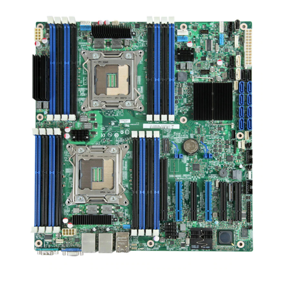
Page 21: Server Board Layout
Intel Server Board S2600CP and Server System P4000CP TPS Intel® Server Board S2600CP Overview ® Server Board Layout ® Figure 1. Intel Server Board S2600CP4, Quad NIC Revision 1.1 Intel order number G26942-003... -
Page 22: Figure 2. Intel ® Server Board S2600Cp2, Dual Nic
Intel® Server Board S2600CP Overview Intel Server Board S2600CP and Server System P4000CP TPS ® ® Figure 2. Intel Server Board S2600CP2, Dual NIC Revision 1.1 Intel order number G26942-003... -
Page 23: Server Board Connector And Component Layout
Intel Server Board S2600CP and Server System P4000CP TPS Intel® Server Board S2600CP Overview ® ® Figure 3. Intel Server Board S2600CP2J, Dual NIC 2.2.1 Server Board Connector and Component Layout The following figure shows the layout of the server board. Each connector and major component is identified by a number or letter, and a description is given below the figure. - Page 24 Intel® Server Board S2600CP Overview Intel Server Board S2600CP and Server System P4000CP TPS ® Callout Description Callout Description Slot 1, PCI Express* Gen3 System Fan 4 connector RMM4 LITE Internal eUSB SSD RMM4 NIC Slot 2, PCI Express* Gen3...
-
Page 25: Figure 4. Major Board Components
Intel Server Board S2600CP and Server System P4000CP TPS Intel® Server Board S2600CP Overview ® Callout Description Callout Description System Status LED SATA 3G connector ID LED SATA 6G connector Diagnostic LED SATA SGPIO SATA/SAS 3G connector (NOT ® ®... -
Page 26: Server Board Mechanical Drawings
Intel® Server Board S2600CP Overview Intel Server Board S2600CP and Server System P4000CP TPS ® 2.2.2 Server Board Mechanical Drawings Figure 5. Mounting Hole Locations (1 of 2) Revision 1.1 Intel order number G26942-003... -
Page 27: Figure 6. Mounting Hole Locations (2 Of 2)
Intel Server Board S2600CP and Server System P4000CP TPS Intel® Server Board S2600CP Overview ® Figure 6. Mounting Hole Locations (2 of 2) Revision 1.1 Intel order number G26942-003... -
Page 28: Figure 7. Major Connector Pin-1 Locations (1 Of 3)
Intel® Server Board S2600CP Overview Intel Server Board S2600CP and Server System P4000CP TPS ® Figure 7. Major Connector Pin-1 Locations (1 of 3) Revision 1.1 Intel order number G26942-003... -
Page 29: Figure 8. Major Connector Pin-1 Locations (2 Of 3)
Intel Server Board S2600CP and Server System P4000CP TPS Intel® Server Board S2600CP Overview ® Figure 8. Major Connector Pin-1 Locations (2 of 3) Revision 1.1 Intel order number G26942-003... -
Page 30: Figure 9. Major Connector Pin-1 Locations (3 Of 3)
Intel® Server Board S2600CP Overview Intel Server Board S2600CP and Server System P4000CP TPS ® Figure 9. Major Connector Pin-1 Locations (3 of 3) Revision 1.1 Intel order number G26942-003... -
Page 31: Figure 10. Primary Side Keep-Out Zone (1 Of 2)
Intel Server Board S2600CP and Server System P4000CP TPS Intel® Server Board S2600CP Overview ® Figure 10. Primary Side Keep-out Zone (1 of 2) Revision 1.1 Intel order number G26942-003... -
Page 32: Figure 11. Primary Side Card-Side Keep-Out Zone
Intel® Server Board S2600CP Overview Intel Server Board S2600CP and Server System P4000CP TPS ® Figure 11. Primary Side Card-Side Keep-out Zone Revision 1.1 Intel order number G26942-003... -
Page 33: Figure 12. Second Side Keep-Out Zone
Intel Server Board S2600CP and Server System P4000CP TPS Intel® Server Board S2600CP Overview ® Figure 12. Second Side Keep-out Zone Revision 1.1 Intel order number G26942-003... -
Page 34: Server Board Rear I/O Layout
NIC Port 1, USB Port 0 (top) and 1 ID LED (bottom) NIC Port 2, USB Port 2 (top) and 3 System Status LED (bottom) ® Figure 13. Rear I/O Layout of Intel Server Board S2600CP4 Revision 1.1 Intel order number G26942-003... -
Page 35: Figure 14. Rear I/O Layout Of Intel ® Server Board S2600Cp2/S2600Cp2J
NIC Port 1, USB Port 0 (top) and 1 System Status LED (bottom) NIC Port 2, USB Port 2 (top) and 3 (bottom) ® Figure 14. Rear I/O Layout of Intel Server Board S2600CP2/S2600CP2J Revision 1.1 Intel order number G26942-003... -
Page 36: Intel Server System P4000Cp Overview
HDD cage allows support for up to eight hot-swap SATA/SAS drives. Five redundant ® hot-swap fans (80x38mm) at the front edge of the chassis and one air duct for Intel Server Board. Three 5.25-inch half-height peripheral bays are available for the installation of a floppy drive, CD-ROM drive, and/or other accessories. -
Page 37: Table 2. Intel ® Server System P4000Cp Family Features
HDD cage allows support for up to eight 2.5" hot-swap SATA/SAS drives. Five ® redundant hot-swap fans (80x38mm) at the front edge of the chassis and one air duct for Intel Server Board. Three 5.25-inch half-height peripheral bays are available for the installation of a floppy drive, CD-ROM drive, and/or other accessories. -
Page 38: Intel ® Server System P4000Cp Family View
One combined header consists of a 24-pin SSI-EEB compliant front panel header and a 4-pin header for optional NIC3/4 LED ® One 1x7pin header for optional Intel Local Control Panel support Video Support Integrated Matrox* G200 2D Video Graphics controller ®... -
Page 39: Intel Server System P4308Cp4Mhgc View
Intel Server Board S2600CP and Server System P4000CP TPS Intel® Server System P4000CP Overview ® E. AC Input Power Connector Serial Port Knockout G. A Kensington* Cable Lock Mounting Hole H. Padlock Loop Alternate RMM4 Knockout Front Control Panel K. 5.25” Peripheral Bays Fixed System Fan M. -
Page 40: Intel Server System P4208Cp4Mhgc View
Intel® Server System P4000CP Overview Intel Server Board S2600CP and Server System P4000CP TPS ® ® Intel RAID C600 Upgrade Key RKSATA8 Q. PCI-e Retainer ® Figure 16. Intel Server System P4308CP4MHGC View Note: Airduct is not shown. 3.2.3 Intel Server System P4208CP4MHGC View ®... -
Page 41: Intel ® Server Board S2600Cp Functional Architecture
Intel Server Board S2600CP Functional Architecture ® ® ® The architecture and design of the Intel Server Board S2600CP is based on the Intel Xeon ® ® E5-2600 processor, the Intel C602 or C602J chipset, the Intel Ethernet Controller I350 GbE controller chip, and the Server Engines* Pilot-III Server Management Controller. -
Page 42: Figure 19. Intel ® Server Board S2600Cp2J Functional Block Diagram
Intel® Server Board S2600CP Functional Architecture Intel Server Board S2600CP and Server System P4000CP TPS ® ® ® Figure 19. Intel Server Board S2600CP2J Functional Block Diagram with Intel C602J chipset Revision 1.1 Intel order number G26942-003... -
Page 43: Processor Support
Processor Population Rules Note: Although the server board does support dual-processor configurations consisting of different processors that meet the defined criteria below, Intel does not perform validation testing of this configuration. For optimal system performance in dual-processor configurations, Intel recommends that identical processors be installed. - Page 44 Processor stepping within a common processor family can be mixed as long as it is listed in the processor specification updates published by Intel Corporation. The following table describes mixed processor conditions and recommended actions for all ®...
-
Page 45: Table 3. Mixed Processor Configurations
Intel Server Board S2600CP and Server System P4000CP TPS Intel® Server Board S2600CP Functional Architecture ® Table 3. Mixed Processor Configurations Error Severity System Action Processor family not Fatal The BIOS detects the error condition and responds as follows: Identical ... - Page 46 Logs the POST Error Code into the SEL. Alerts the BMC to set the System Status LED to steady Amber. Displays “0195: PProcessor Intel(R) QPI link frequencies unable to synchronize” message in the Error Manager. Does not disable the processor. Takes Fatal Error action (see above) and will not boot until the fault condition is remedied.
-
Page 47: Processor Functions Overview
CPU, Integrated Memory Controller (iMC), and Integrated IO Module ® (IIO), have been combined into a single processor package and feature per socket; two Intel QuickPath Interconnect point-to-point links capable of up to 8.0 GT/s, up to 40 lanes of Gen 3 PCI Express* links capable of 8.0 GT/s, and 4 lanes of DMI2/PCI Express* Gen 2 interface with... -
Page 48: Integrated Memory Controller (Imc) And Memory Subsystem
Intel® Server Board S2600CP Functional Architecture Intel Server Board S2600CP and Server System P4000CP TPS ® interconnect performance to be achieved in real systems. It has a snoop protocol optimized for low latency and high scalability, as well as packet and lane structures enabling quick completions of transactions. -
Page 49: Table 4. Udimm Support
Intel Server Board S2600CP and Server System P4000CP TPS Intel® Server Board S2600CP Functional Architecture ® Per channel memory test and initialization engine can initialize DRAM to all logical zeros with valid ECC (with or without data scrambler) or a predefined test pattern Isochronous access support for Quality of Service (QoS) ... -
Page 50: Table 5. Rdimm Support
Intel® Server Board S2600CP Functional Architecture Intel Server Board S2600CP and Server System P4000CP TPS ® Table 5. RDIMM Support Speed (MT/s) and Voltage Validated by Slot per Channel (SPC) and DIMM Per Channel (DPC) Ranks Per Memory Capacity Per... -
Page 51: Figure 22. Intel ® Server Board S2600Cp Dimm Slot Layout
Channel F Channel G Channel H ® Figure 22. Intel Server Board S2600CP DIMM Slot Layout ® The following are generic DIMM population requirements that generally apply to both the Intel Server Board S2600CP. Revision 1.1 Intel order number G26942-003... - Page 52 Intel® Server Board S2600CP Functional Architecture Intel Server Board S2600CP and Server System P4000CP TPS ® DIMM slots on any memory channel must be filled following the “farthest fill first” rule. A maximum of 8 ranks can be installed on any one channel, counting all ranks in each ...
- Page 53 Intel Server Board S2600CP and Server System P4000CP TPS Intel® Server Board S2600CP Functional Architecture ® Independent Channel Mode Rank Sparing Mode Mirrored Channel Mode Lockstep Channel Mode Regardless of RAS mode, the requirements for populating within a channel given in the section 4.2.2.2 must be met at all times.
-
Page 54: Processor Integrated I/O Module (Iio)
Intel® Server Board S2600CP Functional Architecture Intel Server Board S2600CP and Server System P4000CP TPS ® 4.2.3 Processor Integrated I/O Module (IIO) The processor’s integrated I/O module provides features traditionally supported through chipset components. The integrated I/O module provides the following features: 4.2.3.1.1... -
Page 55: Figure 23. Intel ® Server Board S2600Cp2/S2600Cp4 Chipset Functional Block Diagram
Intel Server Board S2600CP and Server System P4000CP TPS Intel® Server Board S2600CP Functional Architecture ® ® Figure 23. Intel Server Board S2600CP2/S2600CP4 Chipset Functional Block Diagram ® Figure 24. Intel Server Board S2600CP2J Chipset Functional Block Diagram Revision 1.1... -
Page 56: Digital Media Interface (Dmi)
Intel® Server Board S2600CP Functional Architecture Intel Server Board S2600CP and Server System P4000CP TPS ® ® ® The Intel C600 chipset in the Intel Server Board S2600CP provide a connection point ® between various I/O components and Intel Xeon E5-2600 processors, which includes the... -
Page 57: Serial Attached Scsi (Sas)/Sata Controller
The C600 chipset implements an SPI Interface as an alternative interface for the BIOS flash ® device. The SPI flash is required to support Gigabit Ethernet and Intel Active Management Technology. The C600 chipset supports up to two SPI flash devices with speeds up to 50 MHz. -
Page 58: Advanced Programmable Interrupt Controller (Apic)
Intel® Server Board S2600CP Functional Architecture Intel Server Board S2600CP and Server System P4000CP TPS ® The C600 chipset provides an ISA-Compatible Programmable Interrupt Controller (PIC) that incorporates the functionality of two 82C59 interrupt controllers. In addition, the C600 chipset supports a serial interrupt scheme. -
Page 59: Manageability
SATA ports: Two white 6Gb/sec SATA ports and four black 3Gb/sec SATA ports routed from the AHCI controller labeled as “SATA_0” through “SATA_5” and eight blue 3Gb/sec SATA/SAS ® ports routed from the SCU controller labeled as “SAS_0” through “SAS_7”. On Intel Server Board S2600CP2J, only 6 SATA ports from ACHI controller are available. -
Page 60: Table 8. Intel ® Raid C600 Upgrade Key Options
® Intel RSTe RAID 0,1,10 Additional information for the on-board RAID features and functionality can be found in the Intel ® RAID Software Users Guide (Intel Document Number D29305-015). The storage ports from SCU can be configured with the two embedded software RAID options: ®... -
Page 61: Pci Subsystem
Server Board S2600CP and Server System P4000CP TPS Intel® Server Board S2600CP Functional Architecture ® ® o 4 and 8 Port SAS RAID 5 support provided with appropriate Intel RAID C600 Upgrade Key Maximum drive support = 8 (with or without SAS expander option installed) ... -
Page 62: Integrated Baseboard Management Controller Overview
Intel® Server Board S2600CP Functional Architecture Intel Server Board S2600CP and Server System P4000CP TPS ® Figure 25. PCI Layout Diagram Integrated Baseboard Management Controller Overview The server board utilizes the I/O controller, Graphics Controller, and Baseboard Management features of the Emulex* Pilot-III Management Controller. The following is an overview of the Revision 1.1... -
Page 63: Super I/O Controller
Intel Server Board S2600CP and Server System P4000CP TPS Intel® Server Board S2600CP Functional Architecture ® features as implemented on the server board from each embedded controller. Figure 26. Integrated BMC Functional Block Diagram 4.5.1 Super I/O Controller The integrated super I/O controller provides support for the following features as implemented... -
Page 64: Graphics Controller And Video Support
Intel® Server Board S2600CP Functional Architecture Intel Server Board S2600CP and Server System P4000CP TPS ® 4.5.1.2 Wake-up Control The super I/O contains functionality that allows various events to power on and power off the system. 4.5.2 Graphics Controller and Video Support... -
Page 65: Baseboard Management Controller
Intel Server Board S2600CP and Server System P4000CP TPS Intel® Server Board S2600CP Functional Architecture ® 4.5.3 Baseboard Management Controller The server board utilizes the following features of the embedded baseboard management controller. IPMI 2.0 Compliant 400MHz 32-bit ARM9 processor with memory management unit (MMU) ... -
Page 66: Network Interface
Intel® Server Board S2600CP Functional Architecture Intel Server Board S2600CP and Server System P4000CP TPS ® 4.5.3.2 Integrated BMC Embedded LAN Channel The Integrated BMC hardware includes two dedicated 10/100 network interfaces. These interfaces are not shared with the host system. At any time, only one dedicated interface may be enabled for management traffic. -
Page 67: System Security
Intel® Server Board S2600CP and Server System P4000CP TPS System Security System Security BIOS Password Protection The BIOS uses passwords to prevent unauthorized tampering with the server setup. Passwords can restrict entry to the BIOS Setup, restrict use of the Boot Popup menu, and suppress automatic USB device reordering. -
Page 68: Trusted Platform Module (Tpm) Support
System Security Intel® Server Board S2600CP and Server System P4000CP TPS new USB boot device is attached to the system. A User is restricted from booting in anything other than the Boot Order defined in the Setup by an Administrator. -
Page 69: Physical Presence
5.2.3.1 Security Screen To enter the BIOS Setup, press the F2 function key during boot time when the OEM or Intel logo displays. The following message displays on the diagnostics screen and under the Quiet Boot logo screen: Press <F2>... -
Page 70: Figure 27. Setup Utility - Tpm Configuration Screen
When the Setup is entered, the Main screen displays. The BIOS Setup utility provides the Security screen to enable and set the user and administrative passwords and to lock out the ® front panel buttons so they cannot be used. The Intel Server Board S2600CP provides TPM settings through the security screen. -
Page 71: Intel ® Trusted Execution Technology
® Intel Trusted Execution Technology integrates new security features and capabilities into the ® processor, chipset and other platform components. When used in conjunction with Intel ® Virtualization Technology, Intel Trusted Execution Technology provides hardware-rooted trust for your virtual applications. - Page 72 Technology requires the system to include a TPM v1.2, as defined by the Trusted Computing Group TPM PC Client Specifications, Revision 1.2. When available, Intel Trusted Execution Technology can be enabled or disabled in the processor by a BIOS Setup option.
-
Page 73: Intel Server Board S2600Cp And Intel Server System P4000Cp Platform Management
Intel® Server Board S2600CP and Server System P4000CP TPS Intel® Server Board S2600CP and Intel® Server System P4000CP Platform Management Intel Server Board S2600CP and Intel Server ® ® System P4000CP Platform Management Server Management Function Architecture 6.1.1 Feature Support 6.1.1.1... - Page 74 The following is a list of the ® more significant changes that are common to this generation Integrated BMC based Intel Server boards: Sensor and SEL logging additions/enhancements (for example, additional thermal ...
-
Page 75: Basic And Advanced Features
Intel® Server Board S2600CP and Server System P4000CP TPS Intel® Server Board S2600CP and Intel® Server System P4000CP Platform Management Embedded platform debug feature which allows capture of detailed data for later analysis. Provisioning and inventory enhancements: o Inventory data/system information export (partial SMBIOS table) Enhancements to fan speed control. -
Page 76: Integrated Bmc Hardware: Emulex* Pilot Iii
Intel® Server Board S2600CP and Intel® Server System P4000CP Platform Management Intel® Server Board S2600CP and Server System P4000CP TPS Feature Basic Advanced In-circuit BMC Firmware Update FRB 2 Chassis Intrusion Detection Fan Redundancy Monitoring Hot-Swap Fan Support Acoustic Management... - Page 77 Intel® Server Board S2600CP and Server System P4000CP TPS Intel® Server Board S2600CP and Intel® Server System P4000CP Platform Management Multiple Serial Peripheral Interface (SPI) flash interfaces NAND/Memory interface Sixteen mailbox registers for communication between the BMC and host ...
-
Page 78: Server Management Functional Specifications
Intel® Server Board S2600CP and Intel® Server System P4000CP Platform Management Intel® Server Board S2600CP and Server System P4000CP TPS Figure 28. Integrated BMC Hardware Server Management Functional Specifications 6.2.1 BMC Internal Timestamp Clock The BMC maintains an internal timestamp clock that is used by various BMC subsystems, for example, for time stamping SEL entries. -
Page 79: System Event Log (Sel)
Intel® Server Board S2600CP and Server System P4000CP TPS Intel® Server Board S2600CP and Intel® Server System P4000CP Platform Management 6.2.2 System Event Log (SEL) The BMC implements the system event log as specified in the Intelligent Platform Management Interface Specification, Version 2.0. The SEL is accessible regardless of the system power state through the BMC's in-band and out-of-band interfaces. -
Page 80: Diagnostic Interrupt (Nmi) Button
Intel® Server Board S2600CP and Intel® Server System P4000CP Platform Management Intel® Server Board S2600CP and Server System P4000CP TPS Code Reason for Beep Associated Sensors 1-5-1-4 The system does not power on or PS Status unexpectedly powers off and a power... -
Page 81: Sensor Monitoring
Intel® Server Board S2600CP and Server System P4000CP TPS Intel® Server Board S2600CP and Intel® Server System P4000CP Platform Management FW logs a SEL event indicating that a watchdog-generated BMC reset (either soft or hard reset) has occurred. This event may be logged after the actual reset has occurred. Refer sensor section for details for the related sensor definition. - Page 82 Intel® Server Board S2600CP and Intel® Server System P4000CP Platform Management Intel® Server Board S2600CP and Server System P4000CP TPS [u,l][nr,c,nc] upper non-recoverable, upper critical, upper non-critical, lower non- recoverable, lower critical, lower non-critical uc, lc upper critical, lower critical Event triggers are supported event-generating offsets for discrete type sensors.
-
Page 83: Bmc System Management Health Monitoring
Intel Server Board S2600CP and Server System P4000CP TPS ® Intel® Server Board S2600CP and Intel® Server System P4000CP Platform Management 6.3.3 BMC System Management Health Monitoring The BMC tracks the health of each of its IPMI sensors and report failures by providing a “BMC FW Health”... -
Page 84: Thermal Sensor Input To Fan Speed Control
Intel® Server Board S2600CP and Intel® Server System P4000CP Platform Management Intel Server Board S2600CP and Server System P4000CP TPS ® 6.3.6 Thermal Sensor Input to Fan Speed Control The BMC uses various IPMI sensors as input to the fan speed control. Some of the sensors are IPMI models of actual physical sensors whereas some are “virtual”... -
Page 85: Table 19. Supported Power Supply Status Sensor Offsets
Intel Server Board S2600CP and Server System P4000CP TPS ® Intel® Server Board S2600CP and Intel® Server System P4000CP Platform Management c. Rearm type: Auto The following sensor-specific offsets are supported. Table 19. Supported Power Supply Status Sensor Offsets Offset... -
Page 86: System Event Sensor
Intel® Server Board S2600CP and Intel® Server System P4000CP Platform Management Intel Server Board S2600CP and Server System P4000CP TPS ® Offset Description Event Logging Configuration error – The following codes for configuration errors are put Assertion and into the SEL Event Data 2 byte: Deassertion ... -
Page 87: User Model
Intel Server Board S2600CP and Server System P4000CP TPS ® Intel® Server Board S2600CP and Intel® Server System P4000CP Platform Management Table 21. Standard Channel Assignments Channel ID Interface Supports Sessions Primary IPMB LAN 1 LAN 2 LAN3 ® (Provided by the Intel... -
Page 88: Table 22. Supported Rmcp+ Cipher Suites
Intel® Server Board S2600CP and Intel® Server System P4000CP Platform Management Intel Server Board S2600CP and Server System P4000CP TPS ® provided, so administrating some settings, such as user passwords, through this interface is not advised. Session establishment commands are IPMI commands that do not require authentication or an associated session. - Page 89 Intel Server Board S2600CP and Server System P4000CP TPS ® Intel® Server Board S2600CP and Intel® Server System P4000CP Platform Management 6.4.3.3 RMCP/ASF Messaging The BMC supports RMCP ping discovery in which the BMC responds with a pong message to an RMCP/ASF ping request.
- Page 90 Dedicated Management NIC MAC Address ® Intel Server Board S2600CP has up to seven MAC addresses assigned to it at the Intel factory. The printed MAC address is assigned to NIC1 on the server board. There will be seven MAC addresses assigned as follows: NIC 1 MAC address (for OS usage) ...
- Page 91 Server Board S2600CP and Server System P4000CP TPS ® Intel® Server Board S2600CP and Intel® Server System P4000CP Platform Management The BMC supports IPv4 and IPv6 simultaneously so they are both configured separately and completely independently. For example, IPv4 can be DHCP configured while IPv6 is statically configured or vice versa.
- Page 92 Intel® Server Board S2600CP and Intel® Server System P4000CP Platform Management Intel Server Board S2600CP and Server System P4000CP TPS ® is configured and enabled, the BMC only accepts packets with that VLAN tag/ID. Conversely, all BMC generated LAN packets on the channel include the given VLAN tag/ID. Valid VLAN ID’s are 1 through 4094, VLAN ID’s of 0 and 4095 are reserved, per the 802.1Q VLAN specification.
-
Page 93: Table 24. Factory Configured Pef Table Entries
Server Board S2600CP and Server System P4000CP TPS ® Intel® Server Board S2600CP and Intel® Server System P4000CP Platform Management Activating a SOL session requires an existing IPMI-over-LAN session. If encryption is used, it should be negotiated when the IPMI-over LAN session is established. SOL sessions are only supported on serial port 1 (COM1). - Page 94 Intel® Server Board S2600CP and Intel® Server System P4000CP Platform Management Intel Server Board S2600CP and Server System P4000CP TPS ® The BMC supports a minimum of four LAN alert destinations. 6.4.3.14.1 SNMP Platform Event Traps (PETs) This feature enables a target system to send SNMP traps to a designated IP address by means of LAN.
- Page 95 Server Board S2600CP and Server System P4000CP TPS ® Intel® Server Board S2600CP and Intel® Server System P4000CP Platform Management The embedded web user interface supports strong security (authentication, encryption, and firewall support) since it enables remote server configuration and control. Embedded web server uses ports #80 and #443.
- Page 96 Intel engineer for an enhanced debugging capability. The files are compressed, encrypted, and password protected. The file is not meant to be viewable by the end user but rather to provide additional debugging capability to an Intel support engineer.
-
Page 97: Advanced Management Feature Support
Intel Server Board S2600CP and Server System P4000CP TPS ® Intel® Server Board S2600CP and Intel® Server System P4000CP Platform Management 6.4.3.20 Data Center Management Interface (DCMI) The DCMI specification is an emerging standard that is targeted to provide a simplified management interface for Internet Portal Data Center (IPDC) customers. -
Page 98: Keyboard, Video, Mouse (Kvm) Redirection
Intel® Server Board S2600CP and Intel® Server System P4000CP Platform Management Intel Server Board S2600CP and Server System P4000CP TPS ® ® Intel Integrated BMC Comprehensive IPMI based base manageability features ® Intel Remote Management Module 4 – Lite No dedicated NIC for management Package contains one module –... -
Page 99: Media Redirection
Intel Server Board S2600CP and Server System P4000CP TPS ® Intel® Server Board S2600CP and Intel® Server System P4000CP Platform Management 6.5.2.1 Force-enter BIOS Setup KVM redirection can present an option to force-enter BIOS Setup. This enables the system to enter F2 setup while booting which is often missed by the time the remote console redirects the video. -
Page 100: Intel Intelligent Power Node Manager (Nm)
Intel® Server Board S2600CP and Intel® Server System P4000CP Platform Management Intel Server Board S2600CP and Server System P4000CP TPS ® Intel Intelligent Power Node Manager (NM) ® Power management deals with requirements to manage processor power consumption and manage power at the platform level to meet critical business needs. Node Manager (NM) is a platform resident technology that enforces power capping and thermal-triggered power capping policies for the platform. -
Page 101: Smart/Clst
Intel Server Board S2600CP and Server System P4000CP TPS ® Intel® Server Board S2600CP and Intel® Server System P4000CP Platform Management 6.6.4 SmaRT/CLST The power supply optimization provided by SmaRT/CLST relies on a platform HW capability as well as ME FW support. When a PMBus-compliant power supply detects insufficient input voltage, an overcurrent condition, or an over-temperature condition, it will assert the SMBAlert# signal on the power supply SMBus (that is, the PMBus). -
Page 102: Impact To System Features
Intel® Server Board S2600CP and Intel® Server System P4000CP Platform Management Intel Server Board S2600CP and Server System P4000CP TPS ® 6.7.1 Impact to System Features The following system features are lost or impacted when EU Lot6 mode is enabled: Increased boot time (~15-20s) when system is DC power cycled. -
Page 103: Intel Server Board S2600Cp Connector/Header Locations And Pin-Outs
Intel Server Board S2600CP and Server System P4000CP TPS ® Intel® Server Board S2600CP Connector/Header Locations and Pin-outs Intel Server Board S2600CP Connector/Header ® Locations and Pin-outs Power Connectors 7.1.1 Main Power Connector Main server board power is supplied by one 12-pin power connector. The connector is labeled as “MAIN PWR”... -
Page 104: Front Panel Header
7.2.3 Local Control Panel Connector The server board includes a 7-pin connector that is used when the system is configured with the Intel Local Control Panel with LCD support. The following table provides the pin-out for this connector. Revision 1.1... -
Page 105: On Board Storage Connectors
Intel Server Board S2600CP and Server System P4000CP TPS ® Intel® Server Board S2600CP Connector/Header Locations and Pin-outs Table 31. Local Front Panel Connector Pin-out Signal Name Signal Name SMB_SENSOR_3V3STBY_DATA SMB_SENSOR_3V3STBY_CLK P3V3_AUX FM_LCP_ENTER_N FM_LCP_LEFT_N FM_LCP_RIGHT_N On Board Storage Connectors The server board provides connectors for support of several storage device options. This section provides a functional overview and pin-out of each connector. -
Page 106: Sas Connectors
“SAS_0” to “SAS_3” are enabled and support transfer rates of up to 3Gb/s. The ® connectors labeled from “SAS_4” to “SAS_7” are only enabled when an optional Intel RAID C600 Upgrade Key is installed. The following tables provide the pin-out for each connector. -
Page 107: Hsbp_I2C Header
Management and Security Connectors 7.4.1 RMM4_Lite Connector A 7-pin Intel RMM4 Lite connector is included on the server board to support the optional Intel ® ® Remote Management Module 4. There is no support for third-party management cards on this server board. -
Page 108: Rmm4_Nic Connector
Intel® Server Board S2600CP Connector/Header Locations and Pin-outs Intel Server Board S2600CP and Server System P4000CP TPS ® Table 42. RMM4_Lite Connector Pin-out Signal Name Signal Name P3V3_AUX CS_N 7.4.2 RMM4_NIC Connector Table 43. RMM4_NIC Connector Pin-out Signal Name Signal Name... -
Page 109: Chassis Intrusion Header
Intel Server Board S2600CP and Server System P4000CP TPS ® Intel® Server Board S2600CP Connector/Header Locations and Pin-outs Signal name P3V3 7.4.5 Chassis Intrusion Header The server board includes a 2-pin chassis intrusion header which can be used when the chassis is configured with a chassis intrusion switch. -
Page 110: Cpu Fan Connector
Intel® Server Board S2600CP Connector/Header Locations and Pin-outs Intel Server Board S2600CP and Server System P4000CP TPS ® 7.5.2 CPU FAN Connector The two CPU fan connectors are 4-pin fan connectors. Following table provides the pin-out for CPU fan connectors. -
Page 111: Figure 30. Video Connector Pin-Out
Note: Intel Corporation server boards support peripheral components and can contain a number of high-density VLSI and power delivery components that need adequate airflow to cool. Intel’s own chassis are designed and tested to meet the intended thermal requirements of these components when the fully integrated system is used together. -
Page 112: Intel Server Board S2600Cp Jumper Blocks
Pins 2-3 should not be connected for normal system operation. CMOS Clear) ME Firmware Force Update Mode – Disabled (Default) J1E3: ME Force Update ME Firmware Force Update Mode – Enabled BMC Firmware Force Update Mode – Disabled (Default) J1E4: BMC Revision 1.1 Intel order number G26942-003... -
Page 113: Bios Default (A.k.a Cmos Clear) And Password Reset Usage Procedure
The BIOS Default (that is, CMOS Clear) and Password Reset recovery features are designed such that the desired operation can be achieved with minimal system downtime. The usage procedure for these two features has changed from previous generation Intel server boards. The following procedure outlines the new usage model. -
Page 114: Integrated Bmc Force Update Procedure
ME to load safely onto the flash device. In the unlikely event ME firmware update process fails due to ME not being in the proper update state, the server board provides an Integrated BMC Force Update jumper, which forces the ME into the proper update Revision 1.1 Intel order number G26942-003... -
Page 115: Bios Recovery Jumper
3. Restore the jumper to its original position. 4. Turn on the system power. 5. Re-flash any custom blocks, such as user binary or language blocks. The system should now boot using the updated system BIOS. Revision 1.1 Intel order number G26942-003... -
Page 116: Intel Light Guided Diagnostics
Figure 32. 5-volt Stand-by Status LED Location Fan Fault LED’s Fan fault LEDs are present for the two CPU fans and the one rear system fan. The fan fault LEDs illuminate when the corresponding fan has fault. Revision 1.1 Intel order number G26942-003... -
Page 117: Dimm Fault Leds
The server board provide memory fault LED for each DIMM socket. These LEDs are located as shown in the following figure. The DIMM fault LED illuminates when the corresponding DIMM slot has memory installed and a memory error occurs. Revision 1.1 Intel order number G26942-003... -
Page 118: System Id Led, System Status Led And Post Code Diagnostic Leds
System ID LED, System Status LED and POST Code Diagnostic LEDs The server boards provide LEDs for system ID, system status and POST code. These LEDs are located in the rear I/O area of the server board as shown in the following figure. Revision 1.1 Intel order number G26942-003... -
Page 119: System Id Led
By issuing the appropriate hex IPMI “Chassis Identify” value, the ID LED will either blink blue for 15 seconds and turn off or will blink indefinitely until the appropriate hex IPMI Chassis Identify value is issue to turn it off. Revision 1.1 Intel order number G26942-003... -
Page 120: System Status Led
Minimum number of fans to cool the system not present or failed. Hard drive fault. Power Unit Redundancy sensor – Insufficient resources offset (indicates not enough power supplies present). In non-sparing and non-mirroring mode if the threshold of correctable errors is crossed within the window. Revision 1.1 Intel order number G26942-003... -
Page 121: Post Code Diagnostic Leds
A. Diagnostic LED #7 (MSB LED) E. Diagnostic LED #3 B. Diagnostic LED #6 F. Diagnostic LED #2 C. Diagnostic LED #5 G. Diagnostic LED #1 D. Diagnostic LED #4 H. Diagnostic LED #0 (LSB LED) Revision 1.1 Intel order number G26942-003... -
Page 122: Intel Server System P4000Cp Front Control Panel And Back Panel
This Front Control Panel conforms to SSI specification with one exception that up to 4 LAN act/link LEDs are supported. The common front panel can support either the standard SSI 2x12 cable interconnect (2 LAN ports) or an Intel customized 2x15 cable interconnect (4 LAN ports). The Front Control Panel has the following features: ... -
Page 123: Table 57. Power/Sleep Led Functional States
The server board also provides a header giving access to this LED for add-in controllers. USB Ports – In addition, the front panel provides two USB ports. The USB ports are cabled to the 2x5 connector on the server board. Revision 1.1 Intel order number G26942-003... -
Page 124: Front Control Panel Led Status
Blink Unit selected for identification by software. Chassis Identification No identification. 10.2 Back Panel Overview The following figure shows the layout of Back Panel with 550-W fixed power supply and 750-W redundant power supplies. Revision 1.1 Intel order number G26942-003... -
Page 125: Figure 37. Back Panel Layout With 550-W Fixed Psu
Power Connector Serial-B Port (Optional) Power Connector Kensington* Cable Lock Mounting Hole Power Supply Padlock Loop IO Connectors RMM4 NIC Port (Optional) RMM4 NIC Port (Optional) Figure 38. Back Panel Layout with 750-W Redundant PSUs Revision 1.1 Intel order number G26942-003... -
Page 126: Intel Server System P4000Cp Storage And Peripheral Drive Bays
SATA only or SAS. Each 2.5” hard disk drive is mounted to a drive tray, allowing for hot swap extraction and insertion. Drive trays have a latching mechanism that is used to extract and insert drives from the chassis, and lock the tray in place. Figure 39. 2.5” Hard Disk Drive Cage Revision 1.1 Intel order number G26942-003... -
Page 127: 2.5" Drive Hot-Swap Backplane Overview
The 8x2.5” backplane is attached to the back of the 8x2.5” drive bay assembly. On the front side of each backplane are mounted eight hard disk drive interface connectors (A), each providing both power and I/O signals to attached hard disk drives. Figure 40. 2.5” Backplane, Front Side Revision 1.1 Intel order number G26942-003... -
Page 128: Cypress* Cy8C22545 Enclosure Management Controller
Cypress* CY8C22545 Enclosure Management Controller The backplanes support enclosure management using a Cypress* CY8C22545 Programmable System-on-Chip (PSoC*) device. The CY8C22545 drives the hard drive activity/fault LED, hard drive present signal, and controls hard drive power-up during system power-on. Revision 1.1 Intel order number G26942-003... -
Page 129: 11.2 3.5" Hard Disk Drive Support
Green Activity LED Table 61. 3.5” Hard Disk Drive Status LED States No access and no fault Amber Solid On Hard Drive Fault has occurred Blink RAID rebuild in progress (1 Hz), Identify (2 Hz) Revision 1.1 Intel order number G26942-003... -
Page 130: 3.5" Drive Hot-Swap Backplane Overview
(A), each providing both power and I/O signals to the attached hard disk drives. Figure 43. 3.5” Backplane, Front Side On the backside of each backplane are several connectors. The following illustration identifies each. Revision 1.1 Intel order number G26942-003... -
Page 131: Figure 44. 2.5" Backplane, Back Side
Note: The two SATA 6G connectors from ACHI (white connectors) on server board are not recommended to connect to the 8X3.5 backplane. The LED indicators on the front side of the 8X2.5” drive bay will not light up if used as such. Revision 1.1 Intel order number G26942-003... -
Page 132: Cypress* Cy8C22545 Enclosure Management Controller
Care should be taken when connecting connectors from the SAS expander to the connectors on the backplane because each connector is pre-programmed at the factory to provide specific drive identification mapping. Improper connections may provide undesirable drive mappings. Figure 46. Internal 24-Port SAS Expander Card Revision 1.1 Intel order number G26942-003... -
Page 133: 11.4 Optical Drive Support
11.5 Low Profile eUSB SSD Support The system provides support for a low profile eUSB SSD storage device. A 2mm 2x5-pin connector labeled “eUSB SSD” is used to plug these small flash storage devices. Revision 1.1 Intel order number G26942-003... -
Page 134: Figure 48. Eusb Ssd Support
Two wire small form factor Universal Serial Bus 2.0 (Hi-Speed USB) interface to host. Read Speed up to 35 MB/s and write Speed up to 24 MB/s. Capacity range from 256GB to 32GB. Support USB Mass Storage Class requirements for Boot capability. Revision 1.1 Intel order number G26942-003... -
Page 135: Intel Server System P4000Cp Thermal Management
12.3 System Fans ® Two cooling solutions are used in the Intel Server Chassis P4000M series. The base non- redundant solution consists of two 120 x 38mm fixed fans to provide sufficient system cooling. The second redundant solution is designed for maximum up time by providing five 80 x 38 mm replaceable hot-swap fans. -
Page 136: Redundant Cooling Solution
Server Chassis P4308XXMXXMFEN 12.3.2 Redundant Cooling Solution ® Redundant cooling solution is used in the Intel Server Chassis P4308XXMXXMHGC and P4208XXMHGC. Five hot-swap 80x38mm fans provide cooling for the processors, hard drives, and add-in cards. When any single fan fails, the remaining fans increase in speed and maintain cooling until the failed unit is replaced. -
Page 137: Fan Control
The fans provided in the Intel Server Chassis P4000M Family contains a tachometer signal ® that can be monitored by the server management subsystem of the Intel Server Boards for RPM (Revolutions per Minute) detection. The server board monitors several temperature sensors and adjusts the PWM (Pulse Width Modulated) signal to drive the fan at the appropriate speed. -
Page 138: Intel Server System P4000Cp Power System Options
® ® ® Intel Server System P4308CP4MHEN is equipped with one 550-W power supply. Intel Server System P4308CP4MHGC and P4208MHGC are equipped with two redundant 750-W power supplies and provide power to mother board through a power distribution board. 13.2... -
Page 139: Figure 51. Mechanical Drawing For 550-W Power Supply Enclosure
Intel Server Board S2600CP and Server System P4000CP TPS Intel Server System P4000CP Power System Options ® ® Figure 51. Mechanical Drawing for 550-W Power Supply Enclosure 13.2.1.1 550-W Power Supply Output Wire Harness Listed or recognized component appliance wiring material (AVLV2), CN, rated min 85 ... -
Page 140: Figure 52. Output Cable Harness For 550-W Power Supply
Intel Server System P4000CP Power System Options Intel Server Board S2600CP and Server System P4000CP TPS ® ® Figure 52. Output Cable Harness for 550-W Power Supply Table 63. Power Supply Cable Lengths From Length (mm) To connector # No of pins... -
Page 141: Table 64. P1 Main Power Connector
Intel Server Board S2600CP and Server System P4000CP TPS Intel Server System P4000CP Power System Options ® ® From Length (mm) To connector # No of pins Description Connector for 5.25" SATA Peripheral Power Extension from P4 Connector for 5.25"... -
Page 142: Temperature Requirements
Intel Server System P4000CP Power System Options Intel Server Board S2600CP and Server System P4000CP TPS ® ® Signal 18 awg color Signal 18 awg color Black +12V1 Yellow Black +12V1 Yellow Black +12V1 Yellow Processor/Memory Power Connector (P3) 13.2.1.1.3 ... -
Page 143: Ac Input Requirements
Intel Server Board S2600CP and Server System P4000CP TPS Intel Server System P4000CP Power System Options ® ® Table 69. Thermal Requirements Item Description Units Operating temperature range. ºC Non-operating temperature range. º C non-op Altitude Maximum operating altitude. 3000 meters 13.2.3... -
Page 144: Table 72. Ac Line Holdup Time
Intel Server System P4000CP Power System Options Intel Server Board S2600CP and Server System P4000CP TPS ® ® signals or protection circuits. If the AC dropout lasts longer than the hold up time the power supply recovers and meets all turn on requirements. The power supply meets the AC dropout requirement over rated AC voltages and frequencies. -
Page 145: Efficency
Intel Server Board S2600CP and Server System P4000CP TPS Intel Server System P4000CP Power System Options ® ® 13.2.4 Efficency The following table provides the required minimum efficiency level at various loading conditions. These are provided at three different load levels; 100%, 50% and 20%. Output shall be load according to the proportional loading method defined by 80 Plus in Generalized Internal Power Supply Efficiency Testing Protocol Rev 6.4.3. -
Page 146: Table 77. Loading Conditions
Intel Server System P4000CP Power System Options Intel Server Board S2600CP and Server System P4000CP TPS ® ® Table 77. Loading Conditions 3.3V 5.0V 12V1 12V2 12V3 -12V 5.0V stby Total 3.3V/5V Power Power Power Load1 12.1 11.7 Load2 13.5 11.2... -
Page 147: Table 80. Capacitive Loading Conditions
Intel Server Board S2600CP and Server System P4000CP TPS Intel Server System P4000CP Power System Options ® ® 13.2.5.6 Capacitive Loading The power supply is stable and meets all requirements with the following capacitive loading ranges. Table 80. Capacitive Loading Conditions... -
Page 148: Figure 53. Differential Noise Test Setup
Intel Server System P4000CP Power System Options Intel Server Board S2600CP and Server System P4000CP TPS ® ® Table 81. Ripples and Noise +3.3V +12V 1, 2, 3 -12V +5VSB 50mVp-p 50mVp-p 120mVp-p 200mVp-p 50mVp-p The test set-up shall be as shown below. -
Page 149: Figure 54. Output Voltage Timing
Intel Server Board S2600CP and Server System P4000CP TPS Intel Server System P4000CP Power System Options ® ® Vout Vout vout_off vout rise vout_on Figure 54. Output Voltage Timing Table 83. Turn On/Off Timing Item Description UNITS Delay from AC being applied to 5VSB being within... -
Page 150: Protection Circuits
Intel Server System P4000CP Power System Options Intel Server Board S2600CP and Server System P4000CP TPS ® ® AC Input vout_holdup Vout pwok_low AC_on_delay pwok_off sb_on_delay sb_on_delay pwok_on pwok_off pwok_on PWOK pson_pwok pwok_holdup 5VSB sb_vout 5VSB holdup pson_on_delay PSON AC turn on/off cycle PSON turn on/off cycle Figure 55. -
Page 151: Control And Indicator Functions
Intel Server Board S2600CP and Server System P4000CP TPS Intel Server System P4000CP Power System Options ® ® signal or by an AC power interruption. The table below contains the over voltage limits. The values are measured at the output of the power supply’s pins. The voltage shall never exceed the maximum levels when measured at the power pins of the power supply connector during any single point of fail. -
Page 152: 750-W Power Supply
Intel Server System P4000CP Power System Options Intel Server Board S2600CP and Server System P4000CP TPS ® ® 0.3V ≤ Hysterisis ≤ 1.0V In 1.0-2.0V input voltages range is Disabled required 1.0 V 2.0 V PS is PS is... -
Page 153: Figure 57. 750-W Power Supply Outline Drawing
Intel Server Board S2600CP and Server System P4000CP TPS Intel Server System P4000CP Power System Options ® ® with a 2x25 card edge connector in the system. The AC plugs directly into the external face of the power supply. Refer to the following figure. All dimensions are nominal. -
Page 154: Table 88. Led Characteristics
The power supply uses a bi-color LED: Amber and Green. Below are table showing the LED states for each power supply operating state and the LED’s wavelength characteristics. Refer to the Intel LED Wavelength and Intensity specification for more details. Table 88. LED Characteristics Min λd Wavelength... -
Page 155: Ac Input Requirements
Intel Server Board S2600CP and Server System P4000CP TPS Intel Server System P4000CP Power System Options ® ® 13.3.1.4 Temperature Requirements The power supply operates within all specified limits over the T temperature range. All airflow passes through the power supply and not over the exterior surfaces of the power supply. -
Page 156: Table 92. Ac Input Voltage Range
Intel Server System P4000CP Power System Options Intel Server Board S2600CP and Server System P4000CP TPS ® ® Table 92. AC Input Voltage Range Start up VAC Power Off Parameter Rated Voltage (110) 90 V 100-127 V 140 V 85VAC +/-... -
Page 157: Efficiency
Intel Server Board S2600CP and Server System P4000CP TPS Intel Server System P4000CP Power System Options ® ® Table 94. AC Line Sag Transient Performance AC Line Sag (10sec interval between each sagging) Duration Operating AC Voltage Line Frequency Performance Criteria... -
Page 158: Table 98. Voltage Regulation Limits
Intel Server System P4000CP Power System Options Intel Server Board S2600CP and Server System P4000CP TPS ® ® 13.3.4.2 Standby Output The 12VSB output is present when an AC input greater than the power supply turn on voltage is applied. -
Page 159: Table 101. Ripples And Noise
Intel Server Board S2600CP and Server System P4000CP TPS Intel Server System P4000CP Power System Options ® ® 13.3.4.7 Residual Voltage Immunity in Standby mode The power supply is immune to any residual voltage placed on its outputs (Typically a leakage voltage through the system from standby output) up to 500mV. -
Page 160: Figure 58. Differential Noise Test Setup
Intel Server System P4000CP Power System Options Intel Server Board S2600CP and Server System P4000CP TPS ® ® LOAD MUST BE AC HOT ISOLATED FROM POWER SUPPLY LOAD THE GROUND OF RETURN AC NEUTRAL THE POWER 10uF .1uF SUPPLY AC GROUND... -
Page 161: Protection Circuits
Intel Server Board S2600CP and Server System P4000CP TPS Intel Server System P4000CP Power System Options ® ® AC Input vout_holdup Vout pwok_low AC_on_delay pwok_off sb_on_delay pwok_on sb_on_delay pwok_on PWOK pson pwok_holdup 12Vsb sb_vout 5Vsb_holdup pson_on_delay PSON AC turn on/off cycle PSON turn on/off cycle Figure 59. -
Page 162: Control And Indicator Functions
Intel Server System P4000CP Power System Options Intel Server Board S2600CP and Server System P4000CP TPS ® ® 13.3.5.2 Over Voltage Protection (OVP) The power supply over voltage protection is locally sensed. The power supply shuts down and latchs off after an over voltage condition occurs. This latch is cleared by toggling the PSON signal or by an AC power interruption. -
Page 163: Figure 60. Pson# Required Signal Characteristic
Intel Server Board S2600CP and Server System P4000CP TPS Intel Server System P4000CP Power System Options ® ® 0.3V ≤ Hysterisis ≤ 1.0V In 1.0-2.0V input voltages range is Disabled required 1.0 V 2.0 V PS is PS is... -
Page 164: Thermal Clst
This FW can be updated when in the system and in standby mode and outside the system with power applied to the 12Vstby pins. Refer to the Intel Common Hardware and Firmware Requirements for CRPS Power Supplier for detailed requirements. -
Page 165: Mechanical Overview
+3.3VDC, +5VDC and 5V standby along with additional over current protection circuit for the 12V rails. ® This power distribution board is intended to be used in the Intel Server Chassis P4000M with various common redundant power supplies; 460W, 750W, 1200W, 1600W and DC input 750W. -
Page 166: Dc/Dc Converter Cooling
Intel Server System P4000CP Power System Options Intel Server Board S2600CP and Server System P4000CP TPS ® ® 13.4.1.1 Airflow Requirements The power distribution board shall get enough airflow for cooling DC/DC converters from the fans located in the Power Supply modules. Below is a basic drawing showing airflow direction. -
Page 167: Table 109. Input Connector And Pin Assignment Diagrams
Intel Server Board S2600CP and Server System P4000CP TPS Intel Server System P4000CP Power System Options ® ® Table 109. Input Connector and Pin Assignment Diagrams Name Name +12V +12V +12V +12V +12V +12V +12V +12V +12V +12V +12V +12V... -
Page 168: Table 111. P1 Baseboard Power Connector
Intel Server System P4000CP Power System Options Intel Server Board S2600CP and Server System P4000CP TPS ® ® Length, No of From To connector # pins Description Extension from P8 1x4 legacy HSBP Power Connector Power supply cover exit hole... -
Page 169: Table 113. P1 Processor Power Connector
Intel Server Board S2600CP and Server System P4000CP TPS Intel Server System P4000CP Power System Options ® ® Signal 18 AWG color Signal 18 AWG Color Black +12V1 White Black +12V1 White Processor#1 Power Connector (P3) 13.4.2.2.3 Connector housing: 8-Pin Molex* 39-01-2080 or equivalent ... -
Page 170: Table 117. P8, P9 Legacy Peripheral Power Connectors
Intel Server System P4000CP Power System Options Intel Server Board S2600CP and Server System P4000CP TPS ® ® Table 117. P8, P9 Legacy Peripheral Power Connectors Signal 18 AWG Color +12V3 Green Black Black +5 VDC Table 118. P7, P10, P11 Legacy Peripheral Power Connectors... -
Page 171: Table 121. Remote Sense Requirements
Intel Server Board S2600CP and Server System P4000CP TPS Intel Server System P4000CP Power System Options ® ® Table 121. Remote Sense Requirements Characteristic Requirement +3.3V remote sense input 200 (measure from +3.3V on P1 2x12 connector to +3.3V sense... -
Page 172: Table 124. Dc/Dc Converters Load Ratings
Intel Server System P4000CP Power System Options Intel Server Board S2600CP and Server System P4000CP TPS ® ® 1 x 3.5" 8xHDD HDD1 8x3.5 peripheral bay 8 x 3.5" fixed SATA 2xfixed 2xfixed 2xfixed 2xfixed peripheral bay 8 x 3.5" fixed... -
Page 173: Table 127. Transient Load Requirements
Intel Server Board S2600CP and Server System P4000CP TPS Intel Server System P4000CP Power System Options ® ® 13.4.2.10 DC/DC Converters Dynamic Loading The output voltages remains within limits specified in table above for the step loading and capacitive loading specified in the table below. The load transient repetition rate is only a test specification. -
Page 174: Figure 63. Differential Noise Test Setup
Intel Server System P4000CP Power System Options Intel Server Board S2600CP and Server System P4000CP TPS ® ® Table 129. Ripple and Noise +3.3V -12V +5VSB 50mVp-p 50mVp-p 120mVp-p 50mVp-p The test set-up shall be as shown below. LOAD MUST BE... -
Page 175: Protection Circuits
Intel Server Board S2600CP and Server System P4000CP TPS Intel Server System P4000CP Power System Options ® ® While in Stand-by mode, at no load condition, the residual voltage on each DC/DC converter output does not exceed 100mV. 13.4.3 Protection Circuits The PDB shall shut down all the DC/DC converters on the PDB and the power supply (by PSON) if there is a fault condition on the PDB (OVP or OCP). -
Page 176: Pwok (Power Ok) Signal
Intel Server System P4000CP Power System Options Intel Server Board S2600CP and Server System P4000CP TPS ® ® 13.4.4 PWOK (Power OK) Signal The PDB connects the PWOK signals from the power supply modules and the DC/DC converters to a common PWOK signal. This common PWOK signal connects to the PWOK pin on P1. -
Page 177: Server System P4000Cp Accessories
® 14.1 Intel RAID C600 Upgrade Key ® ® ® Intel RAID C600 Upgrade Keys are used to enable additional storage features on Intel Server ® ® Board S2600CP2/S2600CP4 and Intel Server System P4000CP that use the Intel C600 ®... -
Page 178: Rmm4)
® ® ® ® Intel Remote Management Model 4 (RMM4) includes two components, Intel Remote ® Management Module 4 Lite (RMM4 Lite) and Intel Dedicated Server Management NIC (DMN). RMM4 Lite is the key that can enable advance features of server onboard Integrated BMC. -
Page 179: 14.3 Rack Options
Intel Server System P4000CP Accessories ® ® ® Figure 65. Intel RMM4 For more detail information of RMM4, please refer to Intel ® Remote Management Module 4 Technical Product Specification. 14.3 Rack Options ® Intel Server System P4308CP4MHEN, P4308CP4MHGC and P4208CP4MHGC can be converted to rack systems with the rack bezel and rack rail options. -
Page 180: 15. Design And Environmental Specifications
Intel Corporation cannot be held responsible if components fail or the server board does not operate correctly when used outside any of its published operating or non-operating limits. -
Page 181: 15.3 Mtbf
The following table defines the Intel Server System P4000CP system level operating and non- ® operating environmental limits. Operation of the Intel Server System P4000CP at conditions beyond those shown in the following table may cause permanent damage to the system. -
Page 182: 15.4 Server Board Power Distribution
13,682,860 15.4 Server Board Power Distribution ® This section provides power supply design guidelines for a system using the Intel Server Board S2600CP. The following diagram shows the power distribution implemented on these server boards. For power supply data, please refer to the chapter that describe the power system options including 550W or 750W power supply. -
Page 183: Figure 67. Power Distribution Block Diagram
VR12 SVID (CPU1 Ch-G&H) PVDDQ_GH 3.3V Vddq @ 66A/52A (12A) VDDQ (57A/48A) (1.5V or 1.35V) (4.4A) PVTT_GH (2.8A/2A) ½ Vddq @ 3A/2.2A PVTT_DDR_GH FANS Peripherals HDD, USB, etc. (4A) Figure 67. Power Distribution Block Diagram Revision 1.1 Intel order number G26942-003... -
Page 184: Appendix A: Integration And Usage Tips
Remote Management Module 4 (Intel RMM4) connector is not compatible ® with any previous versions of the Intel Remote Management Module (Product Order Code – AXXRMM, AXXRMM2, and AXXRMM3). Clear the CMOS with AC power cord plugged. Removing the AC power before ... -
Page 185: Appendix B: Compatible Intel® Server Chassis
Appendix B: Compatible Intel® Server Chassis ® Appendix B: Compatible Intel Server Chassis ® ® ® The Intel Server Board S2600CP can be used inside Intel Server Chassis P4000M family. ® Table 141. Compatible Intel Server Chassis Chassis Name System Fans Storage Drives... -
Page 186: Appendix C: Bmc Sensor Tables
Readable offsets consist of the reading type offsets that do not generate events. Event Data Event data is the data that is included in an event message generated by the associated sensor. For threshold-based sensors, these abbreviations are used: R: Reading value T: Threshold value Revision 1.1 Intel order number G26942-003... - Page 187 LED. Standby Some sensors operate on standby power. These sensors may be accessed and/or generate events when the main (system) power is off, but AC power is present. Revision 1.1 Intel order number G26942-003...
-
Page 188: Table 142. Integrated Bmc Core Sensors
Power Unit Redundancy Chassis- sufficient resources. – Trig Offset specific Transition from full (Pwr Unit Redund) redundant state. 04 – Non-redundant: Degraded sufficient resources. Transition from insufficient state. 05 - Non-redundant: Fatal insufficient resources Revision 1.1 Intel order number G26942-003... - Page 189 02 - Log area System Event Log Disabled Specific – Trig Offset reset/cleared (System Event Log) 02 - Undetermined Sensor System Event system H/W failure Specific Fatal System Event Trig Offset 04 – PEF action (System Event) Revision 1.1 Intel order number G26942-003...
- Page 190 06 – Non-Redundant: degraded from fully Degraded redundant. 07 - Redundant degraded from non- Degraded redundant Digital Temperature SSB Thermal Trip Discrete 01 – State Asserted Fatal – Trig Offset (SSB Therm Trip) Revision 1.1 Intel order number G26942-003...
- Page 191 Platform- Degraded [u,l] [c,nc] Analog R, T specific (Platform Specific) c = Non-fatal nc = IO Module2 Temperature Temperature Threshold Platform- Degraded [u,l] [c,nc] Analog R, T specific (I/O Mod2 Temp) c = Non-fatal Revision 1.1 Intel order number G26942-003...
- Page 192 Threshold Platform- Degraded [u,l] [c,nc] Analog R, T specific (Platform Specific) c = Non-fatal nc = Baseboard Temperature 4 Temperature Threshold Platform- Degraded [u,l] [c,nc] Analog R, T specific (Platform Specific) c = Non-fatal Revision 1.1 Intel order number G26942-003...
- Page 193 Degraded [u,l] [c,nc] Analog R, T Platform (Exit Air Temp) c = Non-fatal Specific Network Interface Controller nc = Temperature Threshold Temperature Degraded [u,l] [c,nc] Analog R, T (LAN NIC Temp) c = Non-fatal Revision 1.1 Intel order number G26942-003...
- Page 194 (PS2 Power In) c = Non-fatal Power Supply 1 +12V % of nc = Current Threshold Chassis- Maximum Current Output Degraded [u] [c,nc] Analog R, T specific (PS1 Curr Out %) c = Non-fatal Revision 1.1 Intel order number G26942-003...
- Page 195 Processor 3 Status Processor Platform- Specific – Trig Offset specific (P3 Status) 07 - Presence Sensor 01 - Thermal trip Fatal Processor 4 Status Processor Platform- Specific – Trig Offset specific (P4 Status) 07 - Presence Revision 1.1 Intel order number G26942-003...
- Page 196 Processor 2 ERR2 Timeout Processor Discrete 01 – State Asserted fatal – Trig Offset – (P2 ERR2) Digital Processor 3 ERR2 Timeout Processor Platform- Discrete 01 – State Asserted fatal – Trig Offset – specific (P3 ERR2) Revision 1.1 Intel order number G26942-003...
- Page 197 Temperature Temperature Discrete 01 - Limit exceeded Non-fatal – Trig Offset – (P1 VRD Hot) Processor 2 VRD Digital Temperature Temperature Discrete 01 - Limit exceeded Non-fatal – Trig Offset – (P2 VRD Hot) Revision 1.1 Intel order number G26942-003...
- Page 198 01 - Limit exceeded Non-fatal – Trig Offset – Hot 0-1 (P4 Mem01 VRD Hot) Digital Processor 4 Memory VRD Temperature Discrete 01 - Limit exceeded Non-fatal – Trig Offset – Hot 2-3 (P4 Mem23 VRD Hot) Revision 1.1 Intel order number G26942-003...
- Page 199 = Non-fatal (P3 DIMM Thrm Mrgn1) nc = Processor 3 DIMM Aggregate Temperature Threshold Platform Degraded [u,l] [c,nc] Analog R, T – Thermal Margin 2 Specific c = Non-fatal (P3 DIMM Thrm Mrgn2) Revision 1.1 Intel order number G26942-003...
- Page 200 Global Aggregate Temperature Threshold Platform Analog R, T – Temperature Margin 3 Specific (Agg Therm Mrgn 3) Global Aggregate Temperature Threshold Platform Analog R, T – Temperature Margin 4 Specific (Agg Therm Mrgn 4) Revision 1.1 Intel order number G26942-003...
- Page 201 Degraded [u,l] [c,nc] Analog R, T – c = Non-fatal (BB +1.05Vccp P1) Baseboard +1.05V nc = Voltage Threshold Processor2 Vccp Degraded [u,l] [c,nc] Analog R, T – c = Non-fatal (BB +1.05Vccp P2) Revision 1.1 Intel order number G26942-003...
- Page 202 – c = Non-fatal (BB +1.35 P1LV CD) Baseboard +1.35V P2 Low nc = Voltage Threshold Voltage Memory AB VDDQ Degraded [u,l] [c,nc] Analog R, T – c = Non-fatal (BB +1.35 P2LV AB) Revision 1.1 Intel order number G26942-003...
- Page 203 Redundancy sensors will be only present on systems with appropriate hardware to support redundancy (for instance, fan or power supply). This is only applicable when the system doesn't support redundant fans. When fan redundancy is supported, then the contribution to system state is driven by the fan redundancy sensor. Revision 1.1 Intel order number G26942-003...
-
Page 204: Appendix D: Platform Specific Bmc Appendix
Table 143. IPMI Channel ID Assignments Channel ID Interface Supports Sessions Primary IPMB LAN 1 LAN 2 LAN3 ® (Provided by the Intel Dedicated Server Management NIC) Reserved Secondary IPMB 8– 0Dh Reserved – Self – SMS/Receive Message Queue Notes: Optional HW supported by the server system. -
Page 205: Table 144. Chassis-Specific Sensors
Hot-swap backplane 1(29h) redundant Hot-swap backplane 2(2Ah) PSUs) P1 Therm Margin(74h) P2 Therm Margin(75h) System Fan 2(31h) Memory channels A and B(B0h) Memory channels C and D(B1h) Revision 1.1 Intel order number G26942-003... - Page 206 Memory VR(25h) Hot-swap backplane 1(29h) Hot-swap backplane 2(2Ah) P2 Therm Margin(75h) Memory channels A and B(B0h) System Fan 5 (34h) Memory channels G and H(B3h) BB P2 VR Temp(24h) Revision 1.1 Intel order number G26942-003...
-
Page 207: Table 146. Intel ® Server Chassis P4208Xxm/P4308Xxm (Fixed Fans, Fixed Or Redundant Psus)191 Table 147. Intel ® Server Chassis P4208Xxm (Fixed Fans, Redundant Psus)
460W HS Power Support DPS-460KB A Support Support 1 PS fan Supply 750W HS Power Support DPS-750XB A Support Support 1 PS fan Supply ® Intel Server Chassis P4308XXM (Fixed fans, redundant PSUs) Revision 1.1 Intel order number G26942-003... -
Page 208: Table 148. Intel ® Server Chassis P4308Xxm (Fixed Fans, Redundant Psus)
FRU) 1200W HS Power Support DPS-1200TB A Support Support 2 PS fan Supply Redundant Fans only for Intel Server Chassis ® ® Intel Server Chassis P4208XXM (Redundant fans, redundant PSUs) ® Intel Server Chassis P4308XXM (Redundant fans, redundant PSUs) ... -
Page 209: Appendix E: Post Code Diagnostic Led Decoder
The diagnostic LED #7 is labeled as “MSB”, and the diagnostic LED #0 is labeled as “LSB”. Figure 68. POST Code Diagnostic LED Decoder A – System Status LED B – System ID LED LSB 1 2 3 4 5 6 MSB – Diagnostic LED Revision 1.1 Intel order number G26942-003... -
Page 210: Table 151. Post Progress Code Led Example
0 CPU PEIM (BSP Select) 1 CPU PEIM (AP Init) 0 CPU PEIM (CPU SMM Init) 1 Dxe IPL started DXE Phase 0 DXE Core started 1 DXE NVRAM Init 0 SB RUN Init 1 Dxe CPU Init Revision 1.1 Intel order number G26942-003... - Page 211 1 DXE Configuration Reset 0 INT19 S3 Resume 0 S3 Resume PEIM (S3 started) 1 S3 Resume PEIM (S3 boot script) 0 S3 Resume PEIM (S3 Video Repost) 1 S3 Resume PEIM (S3 OS wake) BIOS Recovery Revision 1.1 Intel order number G26942-003...
-
Page 212: Table 153. Mrc Progress Codes
LEDs, and a system halt command is executed. Fatal MRC error halts do NOT change the state of the System Status LED, and they do NOT get logged as SEL events. The following table lists all MRC fatal errors that are displayed to the Diagnostic LEDs. Revision 1.1 Intel order number G26942-003... -
Page 213: Table 154. Mrc Fatal Error Codes
Upper Nibble Lower Nibble Description MRC Fatal Error Codes No usable memory error Memory is locked by Intel Trusted Execuiton Technology and is inaccessible DDR3 channel training error Memory test failure DIMM configuration population error Indicates a CLTT table structure error Revision 1.1... -
Page 214: Appendix F: Post Error Code
Processor core/thread count mismatch detected Fatal 0192 Processor cache size mismatch detected Fatal 0194 Processor family mismatch detected Fatal 0195 Processor Intel(R) QPI link frequencies unable to synchronize Fatal 0196 Processor model mismatch detected Fatal 0197 Processor frequencies unable to synchronize Fatal 5220... - Page 215 DIMM_F2 failed test/initialization Major 8531 DIMM_F3 failed test/initialization Major 8532 DIMM_G1 failed test/initialization Major 8533 DIMM_G2 failed test/initialization Major 8534 DIMM_G3 failed test/initialization Major 8535 DIMM_H1 failed test/initialization Major 8536 DIMM_H2 failed test/initialization Major Revision 1.1 Intel order number G26942-003...
- Page 216 DIMM_J3 disabled Major 855E DIMM_K1 disabled Major 855F DIMM_K2 disabled Major (Go to 85D0) 8560 DIMM_A1 encountered a Serial Presence Detection (SPD) failure Major 8561 DIMM_A2 encountered a Serial Presence Detection (SPD) failure Major Revision 1.1 Intel order number G26942-003...
- Page 217 DIMM_N1 failed test/initialization Major 85C8 DIMM_N2 failed test/initialization Major 85C9 DIMM_N3 failed test/initialization Major 85CA DIMM_O1 failed test/initialization Major 85CB DIMM_O2 failed test/initialization Major 85CC DIMM_O3 failed test/initialization Major 85CD DIMM_P1 failed test/initialization Major Revision 1.1 Intel order number G26942-003...
- Page 218 TPM device failed self-test. Minor A100 BIOS ACM Error Major A421 PCI component encountered a SERR error Fatal A5A0 PCI Express component encountered a PERR error Minor A5A1 PCI Express component encountered an SERR error Fatal Revision 1.1 Intel order number G26942-003...
-
Page 219: Table 156. Post Error Beep Codes
Codes that are common across all Intel server boards and systems that use same generation chipset are listed in the following table. Each digit in the code is represented by a sequence of beeps whose count is equal to the digit. -
Page 220: Glossary
General Purpose I/O Gunning Transceiver Logic Hot-Swap Controller Hertz (1 cycle/second) Inter-Integrated Circuit Bus ® Intel Architecture Input Buffer I/O Controller Hub ICMB Intelligent Chassis Management Bus IERR Internal Error I/O and Firmware Bridge Revision 1.1 Intel order number G26942-003... - Page 221 Read Only Memory Real-Time Clock (Component of ICH peripheral chip on the server board) Sensor Data Record SECC Single Edge Connector Cartridge SEEPROM Serial Electrically Erasable Programmable Read-Only Memory System Event Log Server Input/Output Revision 1.1 Intel order number G26942-003...
- Page 222 Simple Network Management Protocol To Be Determined Thermal Interface Material UART Universal Asynchronous Receiver/Transmitter User Datagram Protocol UHCI Universal Host Controller Interface Universal time coordinare Voltage Identification Voltage Regulator Down Word 16-bit quantity Zero Insertion Force Revision 1.1 Intel order number G26942-003...
-
Page 223: Reference Documents
Reference Documents ® Reference Documents See the following document for additional information: ® BIOS for EPSD Platforms Based on Intel Xeon Processor E5-4600/2600/2400/1600 Product Families External Product Specification ® EPSD Platforms Based On Intel Xeon Processor E5 4600/2600/2400/1600 Product Families BMC Core Firmware External Product Specification ®...
Need help?
Do you have a question about the S2600CP Family and is the answer not in the manual?
Questions and answers