Sign In
Upload
Manuals
Brands
Intel Manuals
Server Board
S2600CO series
Intel S2600CO series Manuals
Manuals and User Guides for Intel S2600CO series. We have
2
Intel S2600CO series manuals available for free PDF download: Technical Product Specification, User Manual
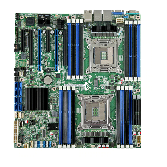
Intel S2600CO series Technical Product Specification (168 pages)
Brand:
Intel
| Category:
Server Board
| Size: 4.28 MB
Table of Contents
Table of Contents
3
List of Tables
8
1 Introduction
12
Chapter Outline
12
Server Board Use Disclaimer
12
Intel Order Number G42278
13
2 Product Overview
14
Table 1. Intel ® Server Board S2600CO Family Feature Set
14
Server Board Connector and Component Layout
16
Figure 1. Major Board Components
17
Figure 2. Intel Light Guided Diagnostic LED Identification
18
Figure 3. Jumper Block Identification
19
Figure 4. Rear I/O Layout
20
Server Board Dimensional Mechanical Drawings
21
Figure 5. Mounting Hole Locations (1 of 2)
21
Figure 6. Mounting Hole Locations (2 of 2)
22
Figure 7. Major Connector Pin-1 Locations
23
Figure 8. Primary Side Keep-Out
24
Figure 9. Secondary Side Keep-Out
25
3 Functional Architecture Overview
26
Figure 10. Intel ® Server Board S2600CO Functional Block Diagram
26
Processor Support
27
Processor Socket Assembly
27
Processor Population Rules
27
Figure 11. Processor Socket Assembly
27
Processor Initializion Error Summary
28
Table 2. Mixed Processor Configurations Error Summary
29
Processor Function Overview
30
Intel Quickpath Interconnect
31
Integrated Memory Controller (IMC) and Memory Subsystem
32
Figure 12. Integrated Memory Controller Functional Block Diagram
32
Table 3. UDIMM Support Guidelines
33
Table 4. RDIMM Support Guidelines
33
Table 5. LRDIMM Support Guidelines
34
Figure 13. Intel ® Server Board S2600CO DIMM Slot Layout
35
Table 6. Intel ® Server Board S2600CO DIMM Nomenclature
35
Processor Integrated I/O Module (IIO)
41
Figure 14. Functional Block Diagram of Processor IIO Sub-System
42
Table 7. Supported Intel Integrated RAID Modules
43
Table 8. Supported Intel Riser Card
44
Table 9. External RJ45 NIC Port LED Definition
44
Intel C600-A Chipset Functional Overview
45
Low Pin Count (LPC) Interface
45
Figure 15. Functional Block Diagram - Chipset Supported Features and Functions
45
Universal Serial Bus (USB) Controller
46
On-Board Serial Attached SCSI (Sas)/Serial ATA (SATA)/RAID Support and Options
46
Figure 16. Intel RAID C600 Upgrade Key Connector
46
Table 10. Intel RAID C600 Upgrade Key Options
47
Manageability
48
Integrated Baseboard Management Controller Overview
49
Figure 17. Integrated BMC Functional Block Diagram
49
Figure 18. Integrated BMC Hardware
50
Super I/O Controller
50
Graphics Controller and Video Support
51
Table 11. Video Modes
51
Baseboard Management Controller
52
Table 12. Video Mode
52
4 Technology Support
54
Intel Trusted Execution Technology
54
VT-X/Vt-D/Vt-C
54
Intel Intelligent Power Node Manager
55
Table 13. Data Center Problems
55
Hardware Requirements
56
5 System Security
57
BIOS Password Protection
57
Trusted Platform Module (TPM) Support
58
TPM Security BIOS
58
Physical Presence
59
TPM Security Setup Options
59
Figure 19. Setup Utility - TPM Configuration Screen
60
Intel Trusted Execution Technology
61
Table 14. Setup Utility - Security Configuration Screen Fields
61
6 Platform Management Functional Overview
63
Baseboard Management Controller (BMC) Firmware Feature Support
63
IPMI 2.0 Features
63
Non IPMI Features
64
New Manageability Features
65
Advanced Configuration and Power Interface (ACPI)
67
Power Control Sources
67
Table 15. ACPI Power States
67
Table 16. Power Control Initiators
67
BMC Watchdog
68
Fault Resilient Booting (FRB)
68
Sensor Monitoring
69
Field Replaceable Unit (FRU) Inventory Device
69
System Event Log (SEL)
70
System Fan Management
70
Thermal and Acoustic Management
70
Fan Profiles
71
Thermal Sensor Input to Fan Speed Control
71
Table 17. Fan Profile Mapping
71
Figure 20. High Level Fan Speed Control Structure
72
Memory Thermal Throttling
73
6.10 Messaging Interfaces
73
User Model
74
IPMB Communication Interface
74
Table 18. Standard ID Channel Assignments
74
LAN Interface
75
Address Resoluton Protocol (ARP)
81
Internet Control Message Protocol (ICMP)
81
Virtual Local Area Network (VLAN)
81
Secure Shell (SSH)
82
Serial-Over-LAN (SOL 2.0)
82
Platform Event Filter
82
Table 19. Factory Configured PEF Table Entries
82
LAN Alterting
83
Altert Policy Table
83
SM-CLP (SM-CLP Lite)
84
Embeded Web Server
84
Virtual Front Panel
86
Embedded Platform Debug
86
Table 20. Diagnostic Data
88
Table 21. Additional Diagnostics on Error
88
Data Center Management Interface (DCMI)
89
Lightweight Directory Authentication Protocol (LDAP)
89
7 Advanced Management Features Support (RMM4)
90
Keyboard, Video, and Mouse (KVM) Redirection
90
Table 22. Intel RMM4 Options Kits
90
Table 23. Enabling Advanced Management Features
90
Performance
91
Remote Console
91
Availability
92
Force-Enter BIOS Setup
92
Security
92
Usage
92
Media Redirection
92
Availability
93
Network Port Usage
93
8 On-Board Connector/Header Overview
94
Power Connectors
94
Main Power
94
CPU Power Connectors
94
Table 24. Main Power Connector Pin-Out ("MAIN PWR")
94
Table 25. CPU Power Connector Pin-Out ("CPU_1 PWR" and "CPU_2 PWR")
94
Pcie Card Power Connectors
95
Front Panel Headers and Connectors
95
SSI Front Panel Header
95
Table 26. Pcie Card Power Connector Pin-Out ("OPT_12V_PWR")
95
Table 27. SSI Front Panel Header Pin-Out ("SSI Front Panel")
95
Table 28. Power/Sleep LED Functional States
96
Table 29. NMI Signal Generation and Event Logging
97
Table 30. System Status LED State Definitions
97
Front Panel USB Connector
99
Intel Local Control Panel Connector
99
On-Board Storage Connectors
99
SATA Only Connectors: 6 Gbps
99
Table 31. Front Panel USB Connector Pin-Out (USB5-6)
99
Table 32. Intel Local Control Pane Connector Pin-Out (LCP)
99
Table 33. SATA Only Connector Pin-Out (SATA_0 and SATA_1)
99
SATA/SAS Connectors
100
SAS SGPIO Connectors
100
Intel ® RAID C600 Upgrade Key Connector
100
HSBP_I2C Header
100
Table 34. SATA/SAS Connector Pin-Out (SATA/SAS_0 to SATA/SAS_7)
100
Table 35. SAS SGPIO Connector Pin-Out (SAS_SPGIO_0 and SAS_SPGIO_1)
100
Table 36. Intel ® RAID C600 Upgrade Key Connector Pin-Out (STRO UPG KEY)
100
Table 37. HSBP_I2C Header Pin-Out (HSBP_I2C)
100
HDD LED Header
101
Internal Type-A USB Connector
101
Internal 2Mm Low Profile Eusb SSD Connector
101
Management and Security Connectors
101
Rmm4_Lite Connector
101
Table 38. Hard Drive Acitivity Header Pin-Out (HDD_LED)
101
Table 39. Internal Type-A USB2.0 Connector Pin-Out (USB_4)
101
Table 40. Internal Eusb Connector Pin-Out (Eusb_Ssd)
101
RMM4_NIC Connector
102
TPM Connector
102
PMBUS Connector
102
Chassis Intrustion Header
102
Table 41. Rmm4_Lite Connector Pin-Out (Rmm4_Lite)
102
Table 42. RMM4_NIC Connector Pin-Out (RMM4_NIC)
102
Table 43. TPM Connector Pin-Out (TPM)
102
Table 44. PMBUS Connector Pin-Out (SMB_PMBUS)
102
IPMB Connector
103
Fan Connectors
103
System FAN Connectors
103
Table 45. Chassis Intrusion Header Pin-Out (CHAS INTR)
103
Table 46. Chassis Instrusion Header State Description
103
Table 47. IPMB Connector Pin-Out (IPMB)
103
Table 48. 6-Pin System FAN Connector Pin-Out (SYS_FAN_1 to SYS_FAN_6)
103
Table 49. 4-Pin System FAN Connector Pin-Out (SYS_FAN_7)
103
CPU FAN Connector
104
Serial Port Connectors
104
Serial Port a Connector (DB9)
104
Serial Port B Connector
104
Video Connector
104
Table 50. CPU Fan Connector Pin-Out (CPU_1 FAN and CPU_2 FAN)
104
Table 51. Serial Port a Connector Pin-Out (SERIAL_A)
104
Table 52. Serial-B Connector Pin-Out (SERIAL_B)
104
Table 53. Rear VGA Video Connector Pinout (VGA)
104
Other Connectors and Headers
105
FAN BOARD_I2C Connector
105
IEEE 1394B Connector
105
Table 54. HSBP 4-PIN I2C BUS Connector Pin out(FAN BOARD_I2C)
105
Table 55. IEEE 1394B Connector Pin out
106
9 Reset and Recovery Jumpers
107
Figure 21. Server Board Jumper Block Locations (J1E2, J1E3, J1E4, J1E6, J2J2)
107
Table 56. Server Board Jumpers (J1E2, J1E3, J1E4, J1E6, J1J2)
107
BIOS Default (A.k.a CMOS Clear) and Password Reset Usage Procedure
108
Set BIOS to Default (A.k.a Clearing the CMOS)
108
Clearing the Password
108
Integrated BMC Force Update Procedure
109
ME Force Update Jumper
109
BIOS Recovery Jumper
110
10 Light Guided Diagnostics
111
10.1 5-Volt Stand-By LED
111
10.2 Fan Fault Leds
111
Figure 22. 5-Volt Stand-By Status LED Location
111
Figure 23. Fan Fault Led's Location
112
10.3 DIMM Fault Leds
113
10.4 System ID LED, System Status LED and POST Code Diagnostic Leds
113
Figure 24. DIMM Fault Led's Location
113
Figure 25. Location of System Status, System ID and POST Code Diagnostic Leds
114
System ID LED
114
POST Code Diagnostic Leds
115
System Status LED
115
Table 57. System Status LED
115
Table 58. POST Code Diagnostic Leds
116
11 Environmental Limits Specification
117
11.1 Processor Thermal Design Power (TDP) Support
117
11.2 Mtbf
117
Table 59. Server Board Design Specifications
117
Table 60. MTBF Estimate
118
12 Power Supply Specification Guidelines
119
12.1 Power Supply DC Output Specification
119
Output Power/Currents
119
Cross Loading
119
Table 61. over Voltage Protection Limits
119
Table 62. Loading Conditions
119
Standby Output
120
Table 63. Voltage Regulation Limits
120
Table 64. Transient Load Requirements
120
Table 65. Capacitive Loading Conditions
121
Table 66. Ripples and Noise
121
Figure 26. Differential Noise Test Setup
122
Table 67. Output Voltage Timing
122
Figure 27. Output Voltage Timing
123
Table 68. Turn On/Off Timing
123
Figure 28. Turn On/Off Timing (Power Supply Signals)
124
Intel Order Number G
124
Appendix A: Integration and Usage Tips
125
Appendix B: Compatiable Intel Server Chassis
126
Figure 29. Intel Server Chassis P4308XXMFEN
126
Figure 30. Intel Server Chassis P4308XXMHGC
127
Figure 31. Chassis/System Product Code Naming Conventions
128
Table 69. Intel Server Chassis P4000M Family Features
129
Appendix C: Integrated BMC Sensor Tables
133
Table 70. BMC Core Sensors
135
Appendix D: Intel Server Board S2600CO Family Specific Sensors
146
Product ID
146
ACPI S3 Sleep State Support
146
Processor Support for Intel Server Board S2600CO
146
Supported Chassis
146
Table 71. Chassis-Specific Sensors
146
Hot-Plug Fan Support
147
Fan Redundancy Support
147
Table 72. Fan Domain Definition
147
HSC Availability
149
Power Unit Support
149
Table 73. Power Supply Support
149
Redundant Fans Only for Intel ® Server Chassis
150
Fan Fault LED Support
150
Memory Throttling Support
150
Appendix E: Management Engine Generated SEL Event Messages
151
Table 74. Server Platform Services Firmware Health Event
151
Table 75. Node Manager Health Event
152
Appendix F: POST Code Diagnostic LED Decoder
153
Table 76. POST Progress Code LED Example
153
Table 77. Diagnostic LED POST Code Decoder
154
Table 78. MRC Progress Codes
156
Table 79. MRC Fatal Error Codes
156
Appendix G: POST Code Errors
158
Table 80. POST Error Codes and Messages
158
Table 81. POST Error Beep Codes
163
Table 82. Integrated BMC Beep Codes
164
Glossary
165
Reference Documents
168
Advertisement
Intel S2600CO series User Manual (167 pages)
server board
Brand:
Intel
| Category:
Server Board
| Size: 2.89 MB
Table of Contents
Revision History
2
Table of Contents
3
List of Tables
8
1 Introduction
13
Chapter Outline
13
Server Board Use Disclaimer
14
2 Product Overview
15
Table 1. Intel Server Board S2600CO Family Feature Set
15
Intel Order Number G42278
16
Server Board Connector and Component Layout
17
Figure 1. Major Board Components
18
Figure 2. Intel Light Guided Diagnostic LED Identification
19
Figure 3. Jumper Block Identification
20
Figure 4. Rear I/O Layout
21
Server Board Dimensional Mechanical Drawings
22
Figure 5. Mounting Hole Locations (1 of 2)
22
Figure 6. Mounting Hole Locations (2 of 2)
23
Figure 7. Major Connector Pin-1 Locations
24
Figure 8. Primary Side Keep-Out
25
Figure 9. Secondary Side Keep-Out
26
3 Functional Architecture Overview
27
Processor Support
28
Processor Socket Assembly
28
Processor Population Rules
28
Figure 11. Processor Socket Assembly
28
Processor Initializion Error Summary
29
Table 2. Mixed Processor Configurations Error Summary
30
Processor Function Overview
31
Intel Quickpath Interconnect
32
Integrated Memory Controller (IMC) and Memory Subsystem
33
Figure 12. Integrated Memory Controller Functional Block Diagram
33
Table 3. UDIMM Support Guidelines
34
Table 4. RDIMM Support Guidelines
34
Table 5. LRDIMM Support Guidelines
35
Table 6. Intel ® Server Board S2600CO DIMM Nomenclature
36
Figure 13. Intel ® Server Board S2600CO DIMM Slot Layout
37
Processor Integrated I/O Module (IIO)
42
Figure 14. Functional Block Diagram of Processor IIO Sub-System
43
Table 7. Supported Intel ® Integrated RAID Modules
44
Table 8. Supported Intel ® Riser Card
45
Table 9. External RJ45 NIC Port LED Definition
45
Intel C600-A Chipset Functional Overview
46
Figure 15. Functional Block Diagram - Chipset Supported Features and Functions
46
Low Pin Count (LPC) Interface
47
Non-Transparent Bridge
47
Universal Serial Bus (USB) Controller
47
Figure 10. Intel
48
Figure 16. Intel RAID C600 Upgrade Key Connector
48
On-Board Serial Attached SCSI (Sas)/Serial ATA (SATA)/RAID Support and Options
48
Table 10. Intel RAID C600 Upgrade Key Options
48
Manageability
50
Integrated Baseboard Management Controller Overview
51
Figure 17. Integrated BMC Functional Block Diagram
51
Figure 18. Integrated BMC Hardware
51
Graphics Controller and Video Support
52
Super I/O Controller
52
Table 11. Video Modes
52
Baseboard Management Controller
53
Table 12. Video Mode
53
4 Technology Support
55
Intel Trusted Execution Technology
55
Intel Virtualization Technology - Intel VT-X/Vt-D/Vt-C
55
Intel Intelligent Power Node Manager
56
Table 13. Data Center Problems
56
Hardware Requirements
57
5 System Security
58
BIOS Password Protection
58
Trusted Platform Module (TPM) Support
59
TPM Security BIOS
59
Physical Presence
60
TPM Security Setup Options
60
Figure 19. Setup Utility - TPM Configuration Screen
61
Intel Trusted Execution Technology
62
Table 14. Setup Utility - Security Configuration Screen Fields
62
6 Platform Management Functional Overview
64
Baseboard Management Controller (BMC) Firmware Feature Support
64
IPMI 2.0 Features
64
Non IPMI Features
65
New Manageability Features
66
Advanced Configuration and Power Interface (ACPI)
67
Power Control Sources
67
Table 15. ACPI Power States
67
Table 16. Power Control Initiators
67
BMC Watchdog
68
Fault Resilient Booting (FRB)
68
Sensor Monitoring
69
Field Replaceable Unit (FRU) Inventory Device
69
System Event Log (SEL)
70
System Fan Management
70
Thermal and Acoustic Management
70
Figure 20. High-Level Fan Speed Control Process
72
Memory Thermal Throttling
73
6.10 Messaging Interfaces
73
User Model
74
IPMB Communication Interface
74
LAN Interface
74
Table 17. Standard ID Channel Assignments
74
Address Resoluton Protocol (ARP)
80
Internet Control Message Protocol (ICMP)
81
Virtual Local Area Network (VLAN)
81
Secure Shell (SSH)
82
Serial-Over-LAN (SOL 2.0)
82
Platform Event Filter
82
Table 18. Factory Configured PEF Table Entries
82
LAN Alterting
83
Altert Policy Table
83
SM-CLP (SM-CLP Lite)
83
Embeded Web Server
84
Virtual Front Panel
85
Embedded Platform Debug
86
Data Center Management Interface (DCMI)
88
Table 19. Diagnostic Data
88
Table 20. Additional Diagnostics on Error
88
Lightweight Directory Authentication Protocol (LDAP)
89
7 Advanced Management Features Support (RMM4)
90
Keyboard, Video, and Mouse (KVM) Redirection
90
Table 21. Intel ® RMM4 Options Kits
90
Table 22. Enabling Advanced Management Features
90
Performance
91
Remote Console
91
Availability
92
Force-Enter BIOS Setup
92
Security
92
Usage
92
Media Redirection
92
Availability
93
Network Port Usage
93
8 On-Board Connector/Header Overview
94
Power Connectors
94
Main Power
94
CPU Power Connectors
94
Table 23. Main Power Connector Pin-Out ("MAIN PWR")
94
Table 24. CPU Power Connector Pin-Out ("CPU_1 PWR" and "CPU_2 PWR")
94
Pcie Card Power Connectors
95
Front Panel Headers and Connectors
95
SSI Front Panel Header
95
Table 25. Pcie Card Power Connector Pin-Out ("OPT_12V_PWR")
95
Table 26. SSI Front Panel Header Pin-Out ("SSI Front Panel")
95
Table 27. Power/Sleep LED Functional States
96
Table 28. NMI Signal Generation and Event Logging
97
Table 29. System Status LED State Definitions
97
Front Panel USB Connector
99
Intel ® Local Control Panel Connector
99
On-Board Storage Connectors
99
Table 30. Front Panel USB Connector Pin-Out (USB5-6)
99
Table 31. Intel ® Local Control Pane Connector Pin-Out (LCP)
99
Intel ® RAID C600 Upgrade Key Connector
100
SAS SGPIO Connectors
100
SATA Only Connectors: 6 Gbps
100
SATA/SAS Connectors
100
Table 32. SATA Only Connector Pin-Out (SATA_0 and SATA_1)
100
Table 33. SATA/SAS Connector Pin-Out (SATA/SAS_0 to SATA/SAS_7)
100
Table 34. SAS SGPIO Connector Pin-Out (SAS_SPGIO_0 and SAS_SPGIO_1)
100
HDD LED Header
101
HSBP_I 2 C Header
101
Internal 2Mm Low Profile Eusb SSD Connector
101
Internal Type-A USB Connector
101
Table 35. Intel RAID C600 Upgrade Key Connector Pin-Out (STRO UPG KEY)
101
Table 36. HSBP_I C Header Pin-Out (HSBP_I C)
101
Table 37. Hard Drive Acitivity Header Pin-Out (HDD_LED)
101
Table 38. Internal Type-A USB 2.0 Connector Pin-Out (USB_4)
101
Management and Security Connectors
102
Rmm4_Lite Connector
102
RMM4_NIC Connector
102
TPM Connector
102
Table 39. Internal Eusb Connector Pin-Out (Eusb_Ssd)
102
Table 40. Rmm4_Lite Connector Pin-Out (Rmm4_Lite)
102
Table 41. RMM4_NIC Connector Pin-Out (RMM4_NIC)
102
Table 42. TPM Connector Pin-Out (TPM)
102
Pmbus* Connector
103
Chassis Intrustion Header
103
IPMB Connector
103
Fan Connectors
103
Table 43. Pmbus* Connector Pin-Out (SMB_PMBUS*)
103
Table 44. Chassis Intrusion Header Pin-Out (CHAS INTR)
103
Table 45. Chassis Instrusion Header State Description
103
Table 46. IPMB Connector Pin-Out (IPMB)
103
CPU FAN Connector
104
System FAN Connectors
104
Serial Port Connectors
104
Serial Port a Connector (DB9)
104
Table 47. 6-Pin System FAN Connector Pin-Out (SYS_FAN_1 to SYS_FAN_6)
104
Table 48. 4-Pin System FAN Connector Pin-Out (SYS_FAN_7)
104
Table 49. CPU Fan Connector Pin-Out (CPU_1 FAN and CPU_2 FAN)
104
Table 50. Serial Port a Connector Pin-Out (SERIAL_A)
104
Serial Port B Connector
105
Video Connector
105
Figure 21. Other Connectors and Headers
105
Table 51. Serial-B Connector Pin-Out (SERIAL_B)
105
Table 52. Rear VGA Video Connector Pinout (VGA)
105
Other Connectors and Headers
106
Fan Board_I
106
Connector
106
IEEE 1394B Connector
106
Table 53. HSBP 4-PIN I C BUS Connector Pin out (FAN BOARD_I C)
106
Table 54. IEEE 1394B Connector Pin out
106
9 Reset and Recovery Jumpers
107
Figure 22. Server Board Jumper Block Locations (J1E2, J1E3, J1E4, J1E6, J2J2)
107
Table 55. Server Board Jumpers (J1E2, J1E3, J1E4, J1E6, J1J2)
107
BIOS Default (that Is, CMOS Clear) and Password Reset Usage Procedure
108
Set BIOS to Default (that Is, Clearing the CMOS)
108
Clearing the Password
108
Integrated BMC Force Update Procedure
109
ME Force Update Jumper
109
BIOS Recovery Jumper
110
10 Light Guided Diagnostics
111
10.1 5 Volt Stand-By LED
111
10.2 Fan Fault Leds
111
Figure 23. 5 Volt Stand-By Status LED Location
111
Figure 24. Fan Fault Led's Location
112
10.3 DIMM Fault Leds
113
10.4 System ID LED, System Status LED and POST Code Diagnostic Leds
113
Figure 25. DIMM Fault Led's Location
113
Figure 26. Location of System Status, System ID and POST Code Diagnostic Leds
114
System ID LED
114
POST Code Diagnostic Leds
115
System Status LED
115
Table 56. System Status LED
115
Table 57. POST Code Diagnostic Leds
116
11 Environmental Limits Specification
117
11.1 Processor Thermal Design Power (TDP) Support
117
Table 58. Server Board Design Specifications
117
11.2 Mtbf
118
Table 59. MTBF Estimate
118
12 Power Supply Specification Guidelines
119
12.1 Power Supply DC Output Specification
119
Output Power/Currents
119
Cross Loading
119
Table 60. over Voltage Protection Limits
119
Table 61. Loading Conditions
119
Standby Output
120
Table 62. Voltage Regulation Limits
120
Table 63. Transient Load Requirements
120
Table 64. Capacitive Loading Conditions
121
Table 65. Ripples and Noise
121
Figure 27. Differential Noise Test Setup
122
Table 66. Output Voltage Timing
122
Figure 28. Output Voltage Timing
123
Table 67. Turn On/Off Timing
123
Figure 29. Turn On/Off Timing (Power Supply Signals)
124
Intel® Server Board S2600Co Family Tps
124
Intel Order Number G
124
Appendix A: Integration and Usage Tips
125
Appendix B: Compatible Intel Server Chassis
126
Figure 30. Intel ® Server Chassis P4000M with Fixed Power Supply, Fixed Hard Drives and Fixed System Fans
126
Figure 31. Intel ® Server Chassis P4000M with Hot-Swap Power Supply, Hot-Swap Hard Drives
127
Figure 32. Chassis/System Product Code Naming Conventions
128
Table 68. Intel ® Server Chassis P4000M Family Features
129
Appendix C: Integrated BMC Sensor Tables
132
Table 69. BMC Core Sensors
134
Appendix D: Intel Server Board S2600CO Family Specific Sensors
145
Product ID
145
ACPI S3 Sleep State Support
145
Processor Support for Intel Server Board S2600CO
145
Supported Chassis
145
Table 70. Chassis-Specific Sensors
145
Hot-Plug Fan Support
146
Fan Redundancy Support
146
Table 71. Fan Domain Definition
146
HSC Availability
148
Power Unit Support
148
Table 72. Power Supply Support
148
Redundant Fans Only for Intel ® Server Chassis
149
Fan Fault LED Support
149
Memory Throttling Support
149
Appendix E: Management Engine Generated SEL Event Messages
150
Table 73. Server Platform Services Firmware Health Event
150
Table 74. Node Manager Health Event
151
Appendix F: POST Code Diagnostic LED Decoder
152
Table 75. POST Progress Code LED Example
152
Table 76. Diagnostic LED POST Code Decoder
153
Table 77. MRC Progress Codes
155
Table 78. MRC Fatal Error Codes
155
Appendix G: POST Code Errors
157
Table 79. POST Error Codes and Messages
157
Table 80. POST Error Beep Codes
162
Glossary
164
Reference Documents
167
Advertisement
Related Products
Intel S2600CO Family
Intel S2600CP Series
Intel S2600WT2
Intel S2600WTT
Intel S2600KPR Series
Intel S2600KP
Intel S2600WT
Intel S2600ST
Intel SE7230NH1-E
Intel SR1475NH1-E
Intel Categories
Motherboard
Computer Hardware
Server
Server Board
Desktop
More Intel Manuals
Login
Sign In
OR
Sign in with Facebook
Sign in with Google
Upload manual
Upload from disk
Upload from URL