
Related Manuals for Intel S1200V3RP


Summary of Contents for Intel S1200V3RP
- Page 1 Intel Server Board S1200V3RP ® Technical Product Specification Intel reference number G84364-004 Revision 1.2 January, 2014...
- Page 2 Revision History Intel® Server Board S1200V3RP TPS Revision History Date Revision Modifications Number November 2012 Preliminary release. Updated BIOS Setup Interface May 2013 Changed the chipset of S1200V3RPL to C226 October 2013 Updated Graphics Controller and Video output: Changed the supporting OS for pGFX Display Port video output to Microsoft Windows 7*.
- Page 3 INFRINGEMENT OF ANY PATENT, COPYRIGHT OR OTHER INTELLECTUAL PROPERTY RIGHT. A "Mission Critical Application" is any application in which failure of the Intel Product could result, directly or indirectly, in personal injury or death. SHOULD YOU PURCHASE OR USE INTEL'S PRODUCTS FOR ANY SUCH MISSION...
-
Page 4: Table Of Contents
Chapter Outline ...................... 1 Server Board Use Disclaimer ................. 2 2. Overview ..........................3 ® Intel Server Boards S1200V3RP product family Feature Set ........ 3 Server Board Layout ....................5 2.2.1 Server Board Connector and Component Layout ........... 5 2.2.2 Server Board Mechanical Drawings ............... - Page 5 Intel® Server Board S1200V3RP TPS Table of Contents 4. System Security ........................ 33 BIOS Password Protection ................... 33 Trusted Platform Module (TPM) Support .............. 34 4.2.1 TPM security BIOS ....................34 4.2.2 Physical Presence ....................35 4.2.3 TPM Security Setup Options ................35 ®...
- Page 6 Table of Contents Intel® Server Board S1200V3RP TPS 6.11.12 SM-CLP (SM-CLP Lite) ..................62 6.11.13 Embedded Web Server ..................63 6.11.14 Virtual Front Panel ....................64 6.11.15 Embedded Platform Debug .................. 65 6.11.16 Data Center Management Interface (DCMI) ............67 6.11.17 Lightweight Directory Authentication Protocol (LDAP) ..........
- Page 7 Intel® Server Board S1200V3RP TPS Table of Contents 8.5.3 SATA Connectors ....................83 8.5.4 Serial Port Connectors ..................83 8.5.5 USB Connector ....................84 8.5.6 I/O Module Connector ..................86 8.5.7 SAS Module Connector ..................87 8.5.8 NIC1 with USB2.0 connector ................88 8.5.9...
- Page 8 Table of Contents Intel® Server Board S1200V3RP TPS 13.1.5 Dynamic Loading ....................215 13.1.6 Capacitive Loading ..................... 215 13.1.7 Grounding ......................215 13.1.8 Residual Voltage Immunity in Standy mode ............215 13.1.9 Common Mode Noise ..................216 13.1.10 Ripple/Noise ....................... 216 13.1.11 Timing Requirements ..................
- Page 9 ® Server Board S1200V3RP – Mounting Hole Locations ........8 Figure 4. Intel ® Server Board S1200V3RP – Major Connector Pin-1 Locations ......9 Figure 5. Intel ® Server Board S1200V3RP – Primary Side Keepout Zone ......... 10 Figure 6. Intel ®...
- Page 10 List of Figures Intel® Server Board S1200V3RP TPS Figure 40. Network Device Order Screen ................185 Figure 41. BEV Device Order Screen ..................186 Figure 42. Add EFI Boot Option Screen .................. 187 Figure 43. Delete EFI Boot Option Screen ................188 Figure 44.
- Page 11 Table 6. Supported Intel Integrated RAID Modules ..............20 ® Table 7. Intel Server Board S1200V3RP SATA Data Transfer Rate ........22 ® Table 8. Intel Server Board S1200V3RP series USB Ports Allocation ........24 Table 9. External RJ45 NIC Port LED Definition ................ 25 Table 10.
- Page 12 List of Tables Intel® Server Board S1200V3RP TPS Table 40. Power/Sleep LED Functional States ................81 Table 41. NMI Signal Generation and Event Logging ..............81 Table 42. VGA Connector Pin-out (J7A1) .................. 82 Table 43. Display Port Connector Pin-out (J8A1) ..............83 Table 44.
- Page 13 Intel® Server Board S1200V3RP TPS List of Tables < This page intentionally left blank. > Revision 1.2 xiii...
-
Page 15: Introduction
External Product Specifications (EPS) or External Design Specifications (EDS) related to this server generation. EPS and EDS documents are made available under NDA with Intel and must be ordered through your local Intel representative. See the Reference Documents section for a list of available documents. -
Page 16: Server Board Use Disclaimer
Very Large Scale Integration (VLSI) and power delivery components that need adequate airflow to cool. Intel ensures through its own chassis development and testing that when Intel server building blocks are used together, the fully integrated system will meet the intended thermal requirements of these components. -
Page 17: Overview
Server Board S1200V3RPL, S1200V3RPS, S1200V3RPO, and S1200V3RPM are monolithic printed circuit boards (PCBs) with features designed to support the pedestal or rack ® ® server markets. These server boards are designed to support the Intel Xeon processor E3 - ®... - Page 18 One DB-15 video connector. ® Two RJ-45 NIC connectors for 10/100/1000 Mb connections through the two Intel Ethernet Controller I210. Two USB 3.0 ports at the back of the board. Two USB 2.0 ports at the back of the board.
-
Page 19: Server Board Layout
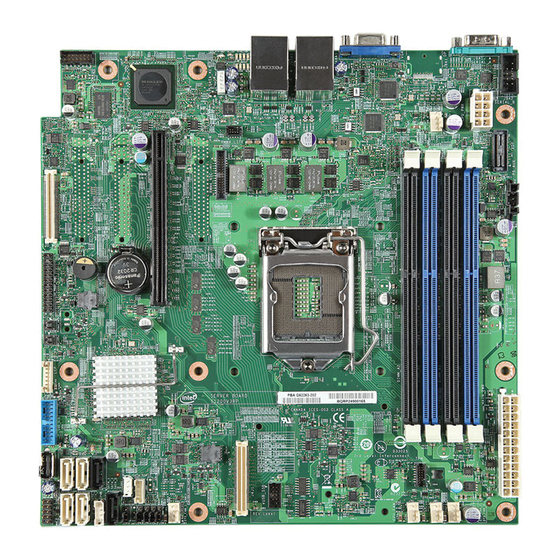
Intel® Server Board S1200V3RP TPS Overview Server Board Layout Figure 1. Intel Server Board S1200V3RP Layout ® 2.2.1 Server Board Connector and Component Layout The following figure shows the layout of the server board. Each connector and major component is identified by a number or letter, and a description is given in the figure below. -
Page 20: Figure 2. Intel Server Board S1200V3Rpl And S1200V3Rps Layout
Overview Intel® Server Board S1200V3RP TPS Figure 2. Intel Server Board S1200V3RPL and S1200V3RPS Layout ® Revision 1.2... -
Page 21: Figure 3. Intel Server Board S1200V3Rpo And S1200V3Rpm Layout
Intel® Server Board S1200V3RP TPS Overview Figure 3. Intel Server Board S1200V3RPO and S1200V3RPM Layout ® Revision 1.2... -
Page 22: Server Board Mechanical Drawings
Overview Intel® Server Board S1200V3RP TPS 2.2.2 Server Board Mechanical Drawings Figure 4. Intel Server Board S1200V3RP – Mounting Hole Locations ® Revision 1.2... -
Page 23: Figure 5. Intel Server Board S1200V3Rp - Major Connector Pin-1 Locations
Intel® Server Board S1200V3RP TPS Overview Figure 5. Intel Server Board S1200V3RP – Major Connector Pin-1 Locations ® Revision 1.2... -
Page 24: Figure 6. Intel Server Board S1200V3Rp - Primary Side Keepout Zone
Overview Intel® Server Board S1200V3RP TPS Figure 6. Intel Server Board S1200V3RP – Primary Side Keepout Zone ® Revision 1.2... -
Page 25: Server Board Rear I/O Layout
Intel® Server Board S1200V3RP TPS Overview Figure 7. Intel Server Board S1200V3RP – Second Side Keepout Zone ® 2.2.3 Server Board Rear I/O Layout The following drawing shows the layout of the rear I/O components for the server board. Figure 8. Intel Server Board S1200V3RP Rear I/O Layout ®... -
Page 26: Functional Architecture
The architecture and design of the Intel Server Board S1200V3RP is based on the Intel C220 ® ® series chipset. The chipset is designed for systems based on the Intel Xeon processor in an LGA 1150 Socket H3 package. ®... -
Page 27: Intel ® Xeon ® Processor E3-1200 V3 Product Family
Intel® Server Board S1200V3RP TPS Functional Architecture ® ® ® Note: The previous generation Intel Xeon processors are not supported on the Intel server board described in this document. 3.1.1 Intel Xeon processor E3-1200 V3 product family ® ® ®... -
Page 28: Integrated Memory Controller (Imc) And Memory Subsystem
Functional Architecture Intel® Server Board S1200V3RP TPS ® Intel 64 Architecture ® ® Intel Streaming SIMD Extensions 4.2 (Intel SSE4.2) ® ® Intel Advanced Vector Extensions 2.0 (Intel AVX2) Advanced Encryption Standard New Instructions (AES-NI) ®... -
Page 29: Supported Memory
3.3.1.1 Memory Population Rules ® Note: Although mixed DIMM configurations are supported, Intel only performs platform validation on systems that are configured with identical DIMMs installed. The processor provides two channels of memory, each capable of supporting up to two DIMMs. -
Page 30: Figure 10. Intel ® Server Board S1200V3Rp Dimm Slot Layout
When only one memory channel is populated, the memory runs in Single Channel mode, with no interleaving. ® On the Intel Server Board S1200V3RP, a total of 4 DIMM slots is provided. The nomenclature for DIMM sockets is detailed in the following table. Table 3. Intel Server Board S1200V3RP DIMM Nomenclature ®... -
Page 31: Memory Ras Features
® For Intel Server Board S1200V3RP product family, the form of Memory RAS provided is Error Correction Code (ECC). ECC uses extra bits – 64-bit data in a 72-bit DRAM array – to add an 8- bit calculated Hamming Code to each 64 bits of data. This additional encoding enables the memory controller to detect and report single or double bit errors, and to correct single-bit errors. -
Page 32: Post Error Codes
Functional Architecture Intel® Server Board S1200V3RP TPS product family board is set at 10 events. When the 10 CE occurs, a single Correctable Error event is logged. 3.3.3 Post Error Codes The range {0xE0 - 0xEF} of POST codes is used for memory errors in early POST. In late POST, this same range of POST code values is used for reporting other system errors. -
Page 33: Table 3. Intel
PCI Express* Gen2 x4 add-in card ® Note: If no device is installed on IO Module connector or Slot5, the device connecting to Intel SAS module connector can work as PCI Express* Gen2 x4 electrical; if any device is installed ®... -
Page 34: Intel ® Integrated Raid Option
4 Port SAS-2.1, Entry-level HW RAID, RMS25KB040 RMS25KB040 IOM Slot RAID Levels 0,1,1E ® For additional product information, refer to the document Intel Integrated RAID Module RMS25KB080, RMS25KB040, RMS25CB080, and RMS25CB040 Hardware User’s Guide. 3.3.6 Optional I/O Module Support ®... -
Page 35: I/O At2)
C220 series Chipset PCH Functional Overview ® ® The following subsections provide an overview of the key features and functions of the Intel C220 series chipset PCH used on the server board. For more comprehensive chipset specific ® information, refer to the Intel... -
Page 36: Digital Media Interface (Dmi)
4; PCI Express* Root Port 8 is configured to support one Gen2 x1 port widths of slot 7. On ® the Intel Server Boards S1200V3RP family product, PCI Express* Root Port 5 is configured to support one Gen1 x1 widths connection with the BMC chip; PCI Express* Root Port 5 and 6 are ®... -
Page 37: Low Pin Count (Lpc) Interface
RAID capability provides high-performance RAID 0, 1, 5, and 10 functionality ® on up to 6 SATA ports of the Intel C220 series chipset. RSTe RAID support is provided to allow multiple RAID levels to be combined on a single set of hard drives, such as RAID 0 and RAID 1 on two disks. -
Page 38: Serial Peripheral Interface (Spi)
5Gb/s. The controller supports SuperSpeed (SS), high-speed (HS), full- speed (FS), and low speed (LS) traffic on the bus. Table 8. Intel Server Board S1200V3RP series USB Ports Allocation ® Rear USB Ports Internal USB Headers... -
Page 39: Gigabit Ethernet Controller
Support USB Mass Storage Class requirements for Boot capability 3.4.7 Gigabit Ethernet Controller ® Network connectivity is provided by means of two onboard Intel Ethernet Controller I210 ® providing up to two 10/100/1000 Mb Ethernet ports. The Intel Ethernet Controller I210 is single, compact, low-power components that offer a fully-integrated Gigabit Ethernet Media Access ®... -
Page 40: Enhanced Power Management
Functional Architecture Intel® Server Board S1200V3RP TPS LED Color LED State NIC State Amber 100 Mbps Green 1000 Mbps Green (Left) Active Connection Blinking Transmit/Receive activity 3.4.7.1 MAC Address Definition ® Each Intel Server Board S1200V3RPL, S1200RPO, or S1200RPM has the following MAC addresses assigned to it at the factory: ... -
Page 41: System Management Bus (Smbus* 2.0)
® Virtualization Technology with Directed I/O (Intel VT-d). Intel VT-d Technology consists of ® technology components that support the virtualization of platforms based on Intel Architecture ® Processors. Intel VT-d Technology enables multiple operating systems and applications to run in independent partitions. A partition behaves like a Virtual Machine (VM) and provides isolation and protection across partitions. -
Page 42: Figure 12. Integrated Baseboard Management Controller (Bmc) Overview
Functional Architecture Intel® Server Board S1200V3RP TPS Figure 12. Integrated Baseboard Management Controller (BMC) Overview Figure 13. Integrated BMC Functional Block Diagram Revision 1.2... -
Page 43: Super I/O Controller
Intel® Server Board S1200V3RP TPS Functional Architecture 3.5.1 Super I/O Controller The integrated super I/O controller provides support for the following features as implemented on the server board: Two Fully Functional Serial Ports, compatible with the 16C550 Serial IRQ Support Up to 16 Shared direct GPIO’s... -
Page 44: Table 11. Video Mode
Functional Architecture Intel® Server Board S1200V3RP TPS The BIOS supports dual-video mode when an add-in video card is installed. In the single mode (dual monitor video = disabled), the on-board video controller is disabled when an add-in video card is detected. -
Page 45: Baseboard Management Controller
Intel® Server Board S1200V3RP TPS Functional Architecture 3.5.3 Baseboard Management Controller The server board utilizes the following features of the embedded baseboard management controller: IPMI 2.0 Compliant 400MHz 32-bit ARM9 processor with memory management unit (MMU) Two independent10/100/1000 Ethernet Controllers with RMII/RGMII support ... - Page 46 Functional Architecture Intel® Server Board S1200V3RP TPS 3.5.3.2 Integrated BMC Embedded LAN Channel The Integrated BMC hardware includes two dedicated 10/100 network interfaces. These interfaces are not shared with the host system. At any time, only one dedicated interface may be enabled for management traffic.
-
Page 47: System Security
Intel® Server Board S1200V3RP TPS System Security System Security BIOS Password Protection The BIOS uses passwords to prevent unauthorized tampering with the server setup. Passwords can restrict entry to the BIOS Setup, restrict use of the Boot Popup menu, and suppress automatic USB device reordering. -
Page 48: Trusted Platform Module (Tpm) Support
System Security Intel® Server Board S1200V3RP TPS prompts for a password, and can only be used with the Administrator password. Also, when a User password is defined, it suppresses the USB Reordering that occurs, if enabled, when a new USB boot device is attached to the system. A User is restricted from booting in anything other than the Boot Order defined in the Setup by an Administrator. -
Page 49: Physical Presence
4.2.3.1 Security Screen ® To enter the BIOS Setup, press the F2 function key during boot time when the OEM or Intel logo displays. The following message displays on the diagnostics screen and under the Quiet Boot logo screen: Press <F2> to enter setup... -
Page 50: Figure 14. Setup Utility - Tpm Configuration Screen
When the Setup is entered, the Main screen displays. The BIOS Setup utility provides the Security screen to enable and set the user and administrative passwords and to lock out the ® front panel buttons so they cannot be used. The Intel Server Board S1200V3RP provides TPM settings through the security screen. -
Page 51: Intel ® Trusted Execution Technology
Technology compatible measured launched environment (MLE). The MLE could consist of a ® virtual machine monitor, an OS, or an application. In addition, Intel Trusted Execution Technology requires the system to include a TPM v1.2, as defined by the Trusted Computing Group TPM PC Client Specification, Revision 1.2. -
Page 52: Intel Technology Support
® The Intel S1200V3RP Server Board Family BIOS publishes the DMAR table in the ACPI Tables. For each DMA Remapping Engine in the platform, one exact entry of DRHD (DMA Remapping Hardware Unit Definition) structure is added to the DMAR. The DRHD structure in turn contains a Device Scope structure that describes the PCI endpoints and/or sub-hierarchies handled by the particular DMA Remapping Engine. -
Page 53: Intel ® Intelligent Power Node Manager
Intel® Server Board S1200V3RP TPS Intel® Technology Support ® For more information on the DMAR table and the DRHD entry format, refer to the Intel Virtualization Technology for Directed I/O Architecture Specification. For more general ® information about VT-x, VT-d, and VT-c, a good reference is Enabling Intel Virtualization Technology Features and Benefits White Paper. - Page 54 PMBus*-compliant power supplies provide the capability to monitoring input power consumption, which is necessary to support NM. ® Following are the some of the applications of Intel Intelligent Power Node Manager technology: Platform Power Monitoring and Limiting: The ME/NM monitors platform power consumption and holds average power over duration.
-
Page 55: Hardware Requirements
Intel® Server Board S1200V3RP TPS Intel® Technology Support Value Vector Capabilities and Features Power and Thermal Concurrent policies Policies Power limiting – OS operational Power limiting – during OS failure Power reduction upon temperature excursion Response SLA 1s(adj) ... -
Page 56: Platform Management Functional Overview
For more in depth and design level Platform Management information, refer to the BMC Core Firmware External Product Specification (EPS) ® and BIOS Core External Product Specification (EPS) for Intel Server products based on the ®... -
Page 57: Non-Ipmi Features
Intel® Server Board S1200V3RP TPS Platform Management Functional Overview See also the Intelligent Platform Management Interface Specification Second Generation v2.0. 6.1.2 Non-IPMI Features The BMC supports the following non-IPMI features. In-circuit BMC firmware update BMC FW reliability enhancements:... -
Page 58: Basic And Advanced Features
Platform Management Functional Overview Intel® Server Board S1200V3RP TPS Address Resolution Protocol (ARP): The BMC sends and responds to ARPs (supported on embedded NICs). Dynamic Host Configuration Protocol (DHCP): The BMC performs DHCP (supported on embedded NICs). ... -
Page 59: Advanced Configuration And Power Interface (Acpi)
Intelligent Power Node Manager Support*** SMASH CLP * Basic management features provided by Integrated BMC ® **Advanced management features available with optional Intel Remote Management Module 4 ® *** Intel Intelligent Power Node Manager Support requires PMBus*-compliant power supply Advanced Configuration and Power Interface (ACPI) The server board supports the following ACPI states. -
Page 60: Power Control Sources
® damage. Intel S1200V3RP Server Platforms introduce a BMC watchdog feature to provide a safe-guard against this scenario by providing an automatic recovery mechanism. It also can provide automatic recovery of functionality that has failed due to a fatal FW defect triggered by a rare sequence of events or a BMC hang due to some type of HW glitch (for example, power). -
Page 61: Fault Resilient Booting (Frb)
Intel® Server Board S1200V3RP TPS Platform Management Functional Overview Reversion of temporary test modes for the BMC back to normal operational modes. FP status LED and DIMM fault LEDs may not reflect BIOS detected errors. Fault Resilient Booting (FRB) Fault resilient booting (FRB) is a set of BIOS and BMC algorithms and hardware support that allow a multiprocessor system to boot even if the bootstrap processor (BSP) fails. -
Page 62: Field Replaceable Unit (Fru) Inventory Device
Any command that results in an overflow of the SEL beyond the allocated space is rejected with an Out of Space IPMI completion code (C4h). Events logged to the SEL can be viewed using Intel’s SELVIEW utility, Embedded Web Server, and Active System Console. -
Page 63: Thermal Sensor Input To Fan Speed Control
Quiet Fan Idle Mode Note: The above features may or may not be in effective depends on the actual thermal ® characters of a specific system. Refer to Intel Server System R1000RP product family ® Technical Product Specification and Intel Server System P4000RP product family Technical Product Specification for system thermal and acoustic management. -
Page 64: Fan Profiles
Platform Management Functional Overview Intel® Server Board S1200V3RP TPS For fan speed control in 3rd party chassis Temperature margin from throttling threshold Absolute temperature PECI value or margin value On-die sensor On-board sensor Virtual sensor Available only when PSU has PMBus* The following illustration provides a simple model showing the fan speed control structure that implements the resulting fan speeds. -
Page 65: Memory Thermal Throttling
Intel® Server Board S1200V3RP TPS Platform Management Functional Overview Type Profile Details OLTT Performance, 3000M altitude CLTT 300M altitude CLTT 900M altitude CLTT 1500M altitude CLTT 3000M altitude Each group of profiles allows for varying fan control policies based on the altitude. For a given... -
Page 66: 6.11 Messaging Interfaces
Platform Management Functional Overview Intel® Server Board S1200V3RP TPS Both Static and Dynamic CLTT modes implement a Hybrid Closed Loop Thermal Throttling mechanism whereby the Integrated Memory Controller estimates the DRAM temperature in between actual reads of the memory thermal sensors. -
Page 67: Ipmb Communication Interface
Intel® Server Board S1200V3RP TPS Platform Management Functional Overview 2. User 2 (“root”) always has the administrator privilege level. 3. All user passwords (including passwords for 1 and 2) may be modified. User IDs 3-15 may be used freely, with the condition that user names are unique. Therefore, no other users can be named “”... - Page 68 Platform Management Functional Overview Intel® Server Board S1200V3RP TPS The baseboard NICs are connected to a single BMC RMII/RGMII port that is configured for RMII operation. The NC-SI protocol is used for this connection and provides a 100 Mb/s full-duplex multi-drop interface which allows multiple NICs to be connected to the BMC.
- Page 69 Intel® Server Board S1200V3RP TPS Platform Management Functional Overview The printed MAC address on the server board and/or server system is assigned to NIC1 on the server board. For security reasons, embedded LAN channels have the following default settings: ...
- Page 70 Platform Management Functional Overview Intel® Server Board S1200V3RP TPS configured by Router Advertisements from the local router. The IP, Prefix, and Gateway are read-only parameters to the BMC user in this mode. Stateless auto-config: The Prefix and Gateway are configured by the router through Router Advertisements.
- Page 71 Intel® Server Board S1200V3RP TPS Platform Management Functional Overview 6.11.3.5.1 Static IP Address (IP Address Source Values 0h, 1h, and 3h) The BMC supports static IP address assignment on all of its management NICs. The IP address source parameter must be set to static before the IP address; the subnet mask or gateway address can be manually set.
- Page 72 Platform Management Functional Overview Intel® Server Board S1200V3RP TPS running DHCP”. Once this parameter is set, the BMC initiates the DHCP process within approximately 100 ms. If the BMC has previously been assigned an IP address through DHCP or the Set LAN Configuration Parameter command, it requests that same IP address to be reassigned.
-
Page 73: Address Resolution Protocol (Arp)
Intel® Server Board S1200V3RP TPS Platform Management Functional Overview User should always set the hostname starting from block selector 1 after the last Update is complete. If the user skips block selector 1 while setting the hostname, the BMC will record the hostname as NULL, because the first block contains NULL data. -
Page 74: Secure Shell (Ssh)
Platform Management Functional Overview Intel® Server Board S1200V3RP TPS Parameter 25 (VLAN Destination Address) of the Set LAN Config Parameters IPMI command is not supported and returns a completion code of 0x80 (parameter not supported) for any read/write of parameter 25. -
Page 75: Lan Alerting
Intel® Server Board S1200V3RP TPS Platform Management Functional Overview Table 20. Factory Configured PEF Table Entries Event Filter Offset Mask Events Number Non-critical, critical and non- Temperature sensor out of range recoverable Non-critical, critical and non- Voltage sensor out of range... -
Page 76: Alert Policy Table
Platform Management Functional Overview Intel® Server Board S1200V3RP TPS 6.11.11 Alert Policy Table Associated with each PEF entry is an alert policy that determines which IPMI channel the alert is to be sent. There is a maximum of 20 alert policy entries. There are no pre-configured entries in the alert policy table because the destination types and alerts may vary by user. -
Page 77: Embedded Web Server
Intel® Server Board S1200V3RP TPS Platform Management Functional Overview The embedded web server is supported over any system NIC port that is enabled for server management capabilities. 6.11.13 Embedded Web Server BMC Base manageability provides an embedded web server and an OEM-customizable web GUI which exposes the manageability features of the BMC base feature set. -
Page 78: Virtual Front Panel
Embedded Platform Debug feature: Allows the user to initiate a diagnostic dump to a file that can be sent to Intel for debug purposes. Virtual Front Panel: The Virtual Front Panel provides the same functionality as the local front panel. -
Page 79: Embedded Platform Debug
Intel engineer for an enhanced debugging capability. The files are compressed, encrypted, and password protected. The file is not meant to be viewable by the end user but rather to provide additional debugging capability to an Intel support engineer. - Page 80 File #2 can be viewed by Intel partners who have signed an NDA with Intel and its contents are restricted to specific data items specified in this with the exception of the BMC syslog messages and power supply black box data.
-
Page 81: Data Center Management Interface (Dcmi)
Intel® Server Board S1200V3RP TPS Platform Management Functional Overview 6.11.15.3 Output Data Categories The following tables list the data to be provided in the diagnostic output. Table 21. Diagnostic Data Category Data Internal BMC Data BMC uptime/load Process list Free Memory... -
Page 82: Lightweight Directory Authentication Protocol (Ldap)
Platform Management Functional Overview Intel® Server Board S1200V3RP TPS 6.11.17 Lightweight Directory Authentication Protocol (LDAP) The Lightweight Directory Access Protocol (LDAP) is an application protocol supported by the BMC for the purpose of authentication and authorization. The BMC user connects with an LDAP server for login authentication. -
Page 83: Advanced Management Feature Support (Rmm4)
Advanced Management Feature Support (RMM4) The integrated baseboard management controller has support for advanced management ® features which are enabled when an optional Intel Remote Management Module 4 (RMM4) is installed. RMM4 is comprised of two boards: RMM4 lite and the optional Dedicated Server Management NIC (DMN). -
Page 84: Keyboard, Video, And Mouse (Kvm) Redirection
Advanced Management Feature Support (RMM4) Intel® Server Board S1200V3RP TPS Figure 17. Intel RMM4 Dedicated Management NIC Installation ® Table 24. Enabling Advanced Management Features Manageability Hardware Benefits ® Intel Integrated BMC Comprehensive IPMI based base manageability features ® Remote Management Module 4 – Lite... -
Page 85: Remote Console
Intel® Server Board S1200V3RP TPS Advanced Management Feature Support (RMM4) keyboard redirection are supported. It is also possible to use the KVM-redirection (KVM-r) session concurrently with media-redirection (media-r). This feature allows a user to interactively use the keyboard, video, and mouse functions of the remote server as if the user were physically at the managed server. -
Page 86: Performance
Advanced Management Feature Support (RMM4) Intel® Server Board S1200V3RP TPS the firewall and, in case of a private internal network, the NAT (Network Address Translation) settings have to be configured accordingly. 7.1.2 Performance The remote display accurately represents the local display. The feature adapts to changes to the video resolution of the local display and continues to work smoothly when the system transitions from graphics to text or vice versa. -
Page 87: Availability
Intel® Server Board S1200V3RP TPS Advanced Management Feature Support (RMM4) Once mounted, the remote device appears just like a local device to the server, allowing system administrators or users to install software (including operating systems), copy files, update BIOS, and so on, or boot the server from this device. - Page 88 Advanced Management Feature Support (RMM4) Intel® Server Board S1200V3RP TPS 5124 – CD Redirection (Secure) 5127 – FD Redirection (Secure) 7578 – Video Redirection 7582 – Video Redirection (Secure) Revision 1.2...
-
Page 89: On-Board Connector/Header Overview
Intel® Server Board S1200V3RP TPS On-board Connector/Header Overview On-board Connector/Header Overview The following section provides detailed information regarding all connectors, headers, and jumpers on the server boards. Board Connector Information The following table lists all connector types available on the board and the corresponding preference designators printed on the silkscreen. -
Page 90: Power Connectors
On-board Connector/Header Overview Intel® Server Board S1200V3RP TPS Connector Quantity Reference Designators Connector Type Pin Count J1K4, J1K1, J1K5, SATA Connector J1K2, J2K5, J2K3 HSBP_I2C J2K4 Header SATA SGPIO J2K2 Header J1G1 Header IPMB J2K1 Header J3K6 (Force Integrated BMC... -
Page 91: System Management Headers
Intel Remote Management Module 4 dedicated NIC module. This server board does not support third-party management cards. ® Note: This connector is not compatible with the previous generation Intel Remote Management ® Modules (Intel RMM/RMM2/RMM3) Table 29. -
Page 92: Tpm Connector
ESRT2 RAID Upgrade Key Connector ® ® The server board provides one connector to support Intel ESRT2 RAID Upgrade Key. The I Upgrade Key is a small PCB board that enables RAID 5 software stack of ESRT2 SW RAID. The pin configuration of connector is identical and defined in the following table: Table 32. -
Page 93: Hsbp_ I 2 C Header
Intel® Server Board S1200V3RP TPS On-board Connector/Header Overview Signal Name FM_LCP_LEFT_N FM_LCP_RIGHT_N 8.3.5 HSBP_ I C Header Table 34. HSBP_ I C Header Pin-out (J2K4) Signal Name SMB_HSBP_3V3STBY_DATA SMB_HSBP_3V3STBY_CLK 8.3.6 HDD LED Header The server board includes a 2-pin hard drive activity LED header used with some SAS/SATA controller add-in cards. -
Page 94: Ipmb Connector
FAN_TACH Front Panel Connector ® The server board provides a 24-pin front panel connector (J1E1) for use with Intel and third- party chassis. The connector consists of a 24-pin SSI compatible front panel connector. The 24- pin SSI front panel connector provides various front panel features including: ... -
Page 95: System Id Button And Led Support
Intel® Server Board S1200V3RP TPS On-board Connector/Header Overview Table 40. Power/Sleep LED Functional States State Power Mode Description Power-off Non-ACPI System power is off, and the BIOS has not initialized the chipset. Power-on Non-ACPI System power is on ACPI Mechanical is off, and the operating system has not saved any context to the hard disk. -
Page 96: Nic Activity Led Support
On-board Connector/Header Overview Intel® Server Board S1200V3RP TPS 8.4.5 NIC Activity LED Support The Front Control Panel includes an activity LED indicator for each on-board Network Interface Controller (NIC). When a network link is detected, the LED will turn on solid. The LED will blink once network activity occurs at a rate that is consistent with the amount of network activity that is occurring. -
Page 97: Display Port Connector
Intel® Server Board S1200V3RP TPS On-board Connector/Header Overview 8.5.2 Display Port Connector The following table details the pin-out definition of the Display Port connector (J8A1). Table 43. Display Port Connector Pin-out (J8A1) Signal Name Description ML_LANE 0 (P) Ground ML_LANE 0 (N) -
Page 98: Usb Connector
On-board Connector/Header Overview Intel® Server Board S1200V3RP TPS Table 45. External DB9 Serial A Port Pin-out (J9A1) Signal Name Description SPA_DCD DCD (carrier detect) SPA_SIN_N RXD (receive data) SPA_OUT_N TXD (Transmit data) SPA_DTR DTR (Data terminal ready) Ground SPA_DSR DSR (data set ready) -
Page 99: Table 48. Internal Usb3.0 Connector Pin-Out (J1J1)
Intel® Server Board S1200V3RP TPS On-board Connector/Header Overview Table 48. Internal USB3.0 Connector Pin-out (J1J1) Signal Description Vbus Power IntA_P1_SSRX- USB3 ICC Port1 SuperSpeed Rx- IntA_P1_SSRX+ USB3 ICC Port1 SuperSpeed Rx+ Ground IntA_P1_SSTX- USB3 ICC Port1 SuperSpeed Tx- IntA_P1_SSTX+ USB3 ICC Port1 SuperSpeed Tx+... -
Page 100: I/O Module Connector
On-board Connector/Header Overview Intel® Server Board S1200V3RP TPS 8.5.6 I/O Module Connector The following table details the pin-out definition of the I/O Module connector (J1C1). Table 51. I/O Module Connector Pin-out (J1C1) Signal Name Signal Name P3V3 P12V P3V3 P12V... -
Page 101: Sas Module Connector
Intel® Server Board S1200V3RP TPS On-board Connector/Header Overview 8.5.7 SAS Module Connector The following table details the pin-out definition of the SAS Module connector (J4J1). Table 52. I/O Module Connector Pin-out (J4J1) Signal Name Signal Name RSVD_PIN1 P12V P12V PE_TP_7... -
Page 102: Nic1 With Usb2.0 Connector
On-board Connector/Header Overview Intel® Server Board S1200V3RP TPS 8.5.8 NIC1 with USB2.0 connector Location: JA6A1 Figure 18. NIC1 with USB2.0 connector 8.5.9 NIC2 with USB3.0 connector Location: JA5A1 Figure 19. NIC2 with USB3.0 connector Revision 1.2... -
Page 103: Fan Headers
Note: Intel Corporation server boards support peripheral components and can contain a number of high-density VLSI and power delivery components that need adequate airflow to cool. Intel’s own chassis are designed and tested to meet the intended thermal requirements of these components when the fully integrated system is used together. -
Page 104: Bios Setup Interface
HotKey and typically the HotKey will be recognized even while other processing is in progress. ® The Intel Server Board S1200V3RP Family BIOS recognizes a number of HotKeys during POST. After the OS is booted, HotKeys are the responsibility of the OS and the OS defines its own set of recognized HotKeys. -
Page 105: Bios Boot Pop-Up Menu
Intel® Server Board S1200V3RP TPS BIOS Setup Interface Mouse devices detected, if any attached Instructions showing HotKeys for going to Setup, going to popup Boot Menu, starting Network Boot BIOS Boot Pop-up Menu The BIOS Boot Specification (BBS) provides a Boot Pop-up menu that can be invoked by pressing the <F6>... -
Page 106: Table 55. Bios Setup Page Layout
BIOS Setup Interface Intel® Server Board S1200V3RP TPS Note: If an Administrative Password has not been set, anyone who boots the system to Setup has access to all selection and data entry fields in Setup and can change any of them. -
Page 107: Table 56. Bios Setup: Keyboard Command Bar
To enter the BIOS Setup using a keyboard (or emulated keyboard), press the <F2> function key during boot time when the OEM or Intel logo is displayed. The following message is displayed on the diagnostics screen and under the Quiet Boot logo screen: Press <F2>... -
Page 108: Bios Setup Utility Screens
BIOS Setup Interface Intel® Server Board S1200V3RP TPS Option Description The down arrow is used to select the next value in a menu item’s option list, Select Menu or a value field’s pick list. The selected item must then be activated by pressing the <Enter>... -
Page 109: Table 57. Screen Map
Intel® Server Board S1200V3RP TPS BIOS Setup Interface In the Option Values entry, the text for default values is shown with an underline. These values do not appear underline on the BIOS Setup screen. The underlined text in this document is to serve as a reference to which value is the default value. -
Page 110: Figure 20. Main Screen
BIOS Setup Interface Intel® Server Board S1200V3RP TPS Categories (Top Tabs) 2nd Level Screens 3rd Level Screens Security Screen (Tab) Server Management Screen (Tab) Console Redirection System Information BMC LAN Configuration Boot Options Screen (Tab) CDROM Order ... - Page 111 Intel® Server Board S1200V3RP TPS BIOS Setup Interface Screen Field Descriptions: 1. Logged in as: Option Values: <Administrator / User> Help Text: <None> Comments: Information only. Displays password level that setup is running in: Administrator or User. With no passwords set, Administrator is the default mode.
- Page 112 Intel® Server Board S1200V3RP TPS Platform: Identifies that this is the correct platform BIOS 86B: Identifies this BIOS as being an Intel Server BIOS Major Revision level of the BIOS Release Revision level for this BIOS zzzz: Release Number for this BIOS Back to [Main Screen] —...
- Page 113 Intel® Server Board S1200V3RP TPS BIOS Setup Interface Comments: Information only. Displays the total physical memory installed in the system, in MB or GB. The term physical memory indicates the total memory discovered in the form of installed DDR3 DIMMs.
- Page 114 BIOS Setup Interface Intel® Server Board S1200V3RP TPS The year must be between 2005 and 2099. Use [Enter] or [Tab] key to select the next field. Use [+] or [-] key to modify the selected field. Comments: This field will initially display the current system day of week and date.
-
Page 115: Figure 21. Advanced Screen
Intel® Server Board S1200V3RP TPS BIOS Setup Interface Figure 21. Advanced Screen Screen Field Descriptions: 1. Processor Configuration Option Values: <None> Help Text: View/Configure processor information and settings. Comments: Selection only. Select this line and press the <Enter> key to go to the Processor Configuration group of configuration settings. - Page 116 BIOS Setup Interface Intel® Server Board S1200V3RP TPS Comments: Selection only. Select this line and press the <Enter> key to go to the Mass Storage Controller Configuration group of configuration settings. Back to [Advanced Screen] — [Screen Map] 4. PCI Configuration Option Values: <None>...
- Page 117 Intel® Server Board S1200V3RP TPS BIOS Setup Interface Comments: Selection only. Select this line and press the <Enter> key to go to the System Acoustic and Performance Configuration group of configuration settings. Back to [Advanced Screen] — [Screen Map] 8. Network Stack Option Values: <None>...
-
Page 118: Figure 22. Processor Configuration Screen
1. Processor ID Option Values: <CPUID> Help Text: <None> Comments: Information only. Displays the Processor Signature value (from the CPUID instruction) identifying the type of processor and the stepping. S1200V3RP series boards have a single Processor ID display. Revision 1.2... - Page 119 Intel® Server Board S1200V3RP TPS BIOS Setup Interface Back to [Advanced Screen] — [Screen Map] 2. Processor Frequency Option Values: <Current Processor Operating Frequency> Help Text: <None> Comments: Information only. Displays current operating frequency of the processor. Back to [Advanced Screen] — [Screen Map] 3.
- Page 120 BIOS Setup Interface Intel® Server Board S1200V3RP TPS Help Text: <None> Comments: Information only. Displays size in MB of the processor L3 Cache. Since L3 cache is shared between all cores in a processor package, this is shown as the total amount of L3 cache per processor package.
- Page 121 Intel® Server Board S1200V3RP TPS BIOS Setup Interface Help Text: Intel(R) Turbo Boost Technology allows the processor to automatically increase its frequency if it is running below power, temperature, and current specifications. Comments: This option is only visible if all processors installed in the system ®...
- Page 122 Option Values: Enabled Disabled Help Text: Intel (R) Hyper-Threading Technology allows multithreaded software applications to execute threads in parallel within each processor. Contact your OS vendor regarding OS support of this feature. Comments: This option is only visible if all processors installed in the system support Intel®...
- Page 123 Comments: This option is only visible if all processors installed in the system support Intel® VT. The software configuration installed on the system must support this feature in order for it to be enabled. Revision 1.2...
- Page 124 Comments: This option is only visible if all processors installed in the system support Intel® VT-d. The software configuration installed on the system must support this feature in order for it to be enabled. Back to [Advanced Screen] — [Screen Map] 19.
- Page 125 Intel® Server Board S1200V3RP TPS BIOS Setup Interface whenever Intel® VT-d is enabled. In that case, this option will be shown as "Enabled", and grayed out and not changeable. Back to [Advanced Screen] — [Screen Map] 21. Intel(R) TXT Option Values:...
- Page 126 BIOS Setup Interface Intel® Server Board S1200V3RP TPS MLC Streamer is a speculative prefetch unit within the processor(s). Note: Modifying this setting may affect performance. Comments: MLC Streamer is normally Enabled, for best efficiency in L2 Cache and Memory Channel use but disabling it may improve performance for some processing loads and on certain benchmarks.
- Page 127 Intel® Server Board S1200V3RP TPS BIOS Setup Interface Disabled Help Text: The next cache line will be prefetched into L1 instruction cache from L2 or system memory during unused cycles if it sees that the processor core has accessed several bytes sequentially in a cache line as data.
-
Page 128: Figure 23. Memory Configuration Screen
BIOS Setup Interface Intel® Server Board S1200V3RP TPS To access this screen from the Main screen, select Advanced > Memory Configuration. To move to another screen, press the <Esc> key to return to the Advanced screen, then select the desired screen. - Page 129 Intel® Server Board S1200V3RP TPS BIOS Setup Interface Comments: Information only. Displays the amount of memory available to the OS in MB or GB. The Effective Memory is the Total Physical Memory minus the sum of all memory reserved for internal usage, RAS redundancy and SMRAM.
- Page 130 BIOS Setup Interface Intel® Server Board S1200V3RP TPS None Help Text: Threshold value for logging Correctable Errors (CE) – Threshold of 10 (default) logs 10th CE, "All" logs every CE and “None”’ means no CE logging. All and None are not valid with Rank Sparing.
- Page 131 2. Not all boards have the same number of channels and slots – this is dependent on the board features. S1200V3RP boards can have DIMMs A1, A2 to B1, B2 Back to [Memory Configuration Screen] — [Advanced Screen] — [Screen Map] 9.4.2.6...
-
Page 132: Figure 24. Mass Storage Controller Configuration Screen
BIOS Setup Interface Intel® Server Board S1200V3RP TPS Figure 24. Mass Storage Controller Configuration Screen Screen Field Descriptions: 1. AHCI Capable SATA Controller Option Values: Disabled Compatibility Enhanced AHCI RAID Mode Help Text: Compatibility provides PATA emulation on the SATA device... - Page 133 Option Values: Intel(R) ESRT2 (LSI*) Intel(R) RSTe Help Text: Intel(R) ESRT2 (Powered by LSI*): Supports RAID 0/1/10 and optional RAID 5 with ® Intel RAID C220 Upgrade Keys. Uses Intel ESRT2 drivers (based on LSI* MegaSR). Intel(R) RSTe: Provides pass-through drive support. Also provides host based RAID 0/1/10/5 support.
- Page 134 BIOS Setup Interface Intel® Server Board S1200V3RP TPS Intel(R) Integrated RAID Module Intel(R) Integrated RAID Module RMS25PB040 Intel(R) Integrated RAID Module RMT3PB080 Intel(R) Integrated RAID Module RMS25CB080 Intel(R) Integrated RAID Module RMS25CB040 Intel(R) Integrated RAID Module RMT3CB080 Intel(R) Integrated RAID Module RMS25JB080...
-
Page 135: Figure 25. Pci Configuration Screen
Intel® Server Board S1200V3RP TPS BIOS Setup Interface It also includes a selection option to go to the NIC Configuration screen. To access this screen from the Main screen, select Advanced > PCI Configuration. To move to another screen, press the <Esc> key to return to the Advanced screen, then select the desired screen. - Page 136 BIOS Setup Interface Intel® Server Board S1200V3RP TPS Back to [PCI Configuration Screen] — [Advanced Screen] — [Screen Map] 2. Memory Mapped I/O above 4 GB Option Values: Enabled Disabled Help Text: Enable or disable memory mapped I/O of 64-bit PCI devices to 4 GB or greater address space.
- Page 137 Intel® Server Board S1200V3RP TPS BIOS Setup Interface Comments: When disabled, the system requires an add-in video card or Processor Integrated graphics for the video to be seen. When there is no add-in video card or Processor Integrated graphics installed, Onboard Video is set to Enabled and grayed out so it cannot be changed.
- Page 138 BIOS Setup Interface Intel® Server Board S1200V3RP TPS Notes: This configuration page is not visible on some SKU. Back to [PCI Configuration Screen] — [Advanced Screen] — [Screen Map] 9.4.2.8 NIC Configuration The NIC Configuration screen allows the user to configure the NIC controller options for BIOS POST.
- Page 139 PXE nor FCoE OPROMs may be enabled for the 1 GbE or 10 GbE NICs. ® FCoE – there is a 10 GbE FCoE Option ROM that supports the Intel 82599 NIC. When it is enabled, the iSCSI OPROM and the 10 GbE PXE OPROM must be disabled.
-
Page 140: Figure 26. Nic Configuration Screen
BIOS Setup Interface Intel® Server Board S1200V3RP TPS Figure 26. NIC Configuration Screen Screen Field Descriptions: 1. Wake on LAN (PME) Revision 1.2... - Page 141 Intel® Server Board S1200V3RP TPS BIOS Setup Interface Option Values: Enabled Disabled Help Text: Enables or disables PCI PME function for Wake on LAN capability from LAN adapters. Comments: Enables/disables PCI/PCIe PME# signal to generate Power Management Events (PME) and ACPI Table entries required for Wake on LAN (WOL).
- Page 142 This selection is to enable/disable the 10GbE FCoE Option ROM that is used by all Onboard and IO Module 10 GbE controllers capable of FCoE support. ® At the present time, only the Intel 82599 10 Gigabit SFP+ NIC supports FCoE for this family of server boards.
- Page 143 Back to [NIC Configuration Screen] — [PCI Configuration Screen] — [Advanced Screen] — [Screen Map] 8. IO Module 1 Type 9. IO Module 2 Type Option Values: <IO Module Description> One of these strings: Intel(R) I350 Quad-Port Gigabit Ethernet Module Intel(R) I540 Dual-Port X540 10 Gigabit RJ-45 Module Revision 1.2...
- Page 144 BIOS Setup Interface Intel® Server Board S1200V3RP TPS Intel(R) 82599 Dual-Port 10 Gigabit SFP+ Module Mellanox* ConnectX-3* Single-Port InfiniBand FD14 Module Help Text: <None> Comments: Information only. This is a display showing which Network Controllers on IO Modules are installed on the baseboard. Each of these IO Module NICs will be followed by a section including a group of options that are specific to the type of NIC, either as an Ethernet controller or an InfiniBand controller.
- Page 145 Intel® Server Board S1200V3RP TPS BIOS Setup Interface 14. IOM2 InfiniBand Option ROM Option Values: Enabled Disabled Help Text: Enable/Disable InfiniBand Controller Option ROM and FlexBoot. Comments: This option will control whether the associated InfiniBand Controller Option ROM is executed by BIOS during POST. This will also control whether the InfiniBand controller FlexBoot program appears in the list of bootable devices.
- Page 146 BIOS Setup Interface Intel® Server Board S1200V3RP TPS 26. IOM2 Port3 PXE 27. IOM2 Port4 PXE Option Values: Enabled Disabled Help Text: Enable/Disable Onboard/IOM NIC Port PXE Boot Comments: This will enable or disable PXE Boot capability for Port<x, x = 1-4>...
-
Page 147: Figure 27. Serial Port Configuration Screen
Intel® Server Board S1200V3RP TPS BIOS Setup Interface 36. IOM2 Port3 MAC Address 37. IOM2 Port4 MAC Address Option Values: <Mac Address Display> Help Text: <None> Comments: Information only. 12 hex digits of the MAC address of Port1- Port4 of the Network Controller corresponding to NIC1, NIC2, IOM1, or IOM2. - Page 148 BIOS Setup Interface Intel® Server Board S1200V3RP TPS Option Values: Enabled Disabled Help Text: Enable or Disable Serial port A. Comments: Serial Port A can be used for either Serial Over LAN or Serial Console Redirection. Back to [Serial Port Configuration Screen] — [Screen Map] 2.
- Page 149 Intel® Server Board S1200V3RP TPS BIOS Setup Interface Help Text: Enable or Disable Serial port B. Comments: Serial Port B can be used for Serial Console Redirection. Back to [Serial Port Configuration Screen] — [Screen Map] 5. Address Option Values:...
-
Page 150: Figure 28. Usb Configuration Screen
BIOS Setup Interface Intel® Server Board S1200V3RP TPS Each USB Mass Storage device may be set to allow the media emulation for which it is formatted, or an emulation may be specified. For USB Flash Memory devices in particular, there are some restrictions: ·... - Page 151 Intel® Server Board S1200V3RP TPS BIOS Setup Interface Comments: Information only. Displays the total number of USB devices of all types which have been detected in POST. Note: There is one USB keyboard and one USB mice detected from the BMC KVM function under this item even no USB devices connected to the system.
- Page 152 BIOS Setup Interface Intel® Server Board S1200V3RP TPS Help Text: Enable/Disable XHCI Pre-Boot Driver support Comments: If the USB controller setting is Disabled, this field is grayed out and inactive. Back to [USB Configuration Screen] — [Screen Map] 5. XHCI Hand-off...
- Page 153 Intel® Server Board S1200V3RP TPS BIOS Setup Interface This may be needed for legacy USB keyboard support when using an OS that is USB unaware. Comments: If the USB controller setting is Disabled, this field is grayed out and inactive.
-
Page 154: Figure 29. System Acoustic And Performance Configuration Screen
BIOS Setup Interface Intel® Server Board S1200V3RP TPS 10. Mass Storage Devices: Option Values: Auto Floppy Forced FDD Hard Disk CD-ROM Help Text: [Auto] - USB devices less than 530 MB are emulated as floppies. [Forced FDD] - HDD formatted drive is emulated as an FDD (e.g., ZIP drive). - Page 155 Comments: The Thermal Throttling Mode chosen reflects whether the DIMMs have Temperature Sensors (TSOD), and whether the chassis is an Intel chassis for which thermal data are available. Note that this is for thermal throttling only, independent of any controls imposed for the purpose of power limiting.
- Page 156 BIOS Setup Interface Intel® Server Board S1200V3RP TPS [Above 1500m](above 4920ft) Optimal performance setting at the highest elevations. Comments: This option sets an altitude value in order to choose a Fan Profile that is optimized for the air density at the current altitude at which the system is installed.
-
Page 157: Figure 30. Network Stack Screen
Intel® Server Board S1200V3RP TPS BIOS Setup Interface Option Values: Enabled Disabled Help Text: Enabling this option allows the system fans to operate in Quiet ‘Fan off’ mode while still maintaining sufficient system cooling. In this mode, fan sensors become unavailable and cannot be monitored. - Page 158 Trusted Platform Module (TPM) security settings on those boards that support TPM. ® Note that it is necessary to activate the TPM in order be able to enable Intel Trusted Execution Technology (TXT) on boards that support it. Changing the TPM state in Setup will require a Hard Reset for the new state to become effective.
-
Page 159: Figure 31. Security Screen
Intel® Server Board S1200V3RP TPS BIOS Setup Interface soon after power on while the BIOS queries for a Power On Password. Either the Administrator or the User password may be entered for a Power on Password. To access this screen from the Main screen or other top-level “Tab” screen, press the right or left arrow keys to traverse the tabs at the top of the Setup screen until the Security screen is selected. - Page 160 BIOS Setup Interface Intel® Server Board S1200V3RP TPS Comments: Information only. Indicates the status of the User Password. Back to [Security Screen] — [Screen Map] 3. Set Administrator Password [Entry Field – 0-14 characters] Option Values: Help Text: Administrator password is used if Power On Password is enabled and to control change access in BIOS Setup.
- Page 161 Intel® Server Board S1200V3RP TPS BIOS Setup Interface Help Text: User password is used if Power On Password is enabled and to allow restricted access to BIOS Setup. Length is 1-14 characters. Case sensitive alphabetic, numeric and special characters !@#$%^&*()-_+=? are allowed.
- Page 162 Intel® Server Board S1200V3RP TPS must be controlled via a system management interface, and the NMI Diagnostic Interrupt is not available. Note: This option is not visible on S1200V3RP Server Board. Back to [Security Screen] — [Screen Map] 7. TPM State Option Values: <Displays current TPM Device State>...
- Page 163 Intel® Server Board S1200V3RP TPS BIOS Setup Interface [Turn On] - Enables and activates TPM. [Turn Off] - Disables and deactivates TPM. [Clear Ownership] - Removes TPM ownership & returns TPM to factory default state. Note: setting returns to [No Operation] on every boot.
-
Page 164: Figure 32. Server Management Screen
BIOS Setup Interface Intel® Server Board S1200V3RP TPS Figure 32. Server Management Screen Screen Field Descriptions: 1. Assert NMI on SERR Option Values: Enabled Disabled Help Text: On SERR, generate an NMI and log an error. Note: [Enabled] must be selected for the Assert NMI on PERR setup option to be visible. - Page 165 Intel® Server Board S1200V3RP TPS BIOS Setup Interface Back to [Server Management Screen] — [Screen Map] 2. Assert NMI on PERR Option Values: Enabled Disabled Help Text: On PERR, generate an NMI and log an error. Note: This option is only active if the Assert NMI on SERR option has [Enabled] selected.
- Page 166 BIOS Setup Interface Intel® Server Board S1200V3RP TPS System action to take on AC power loss recovery. [Stay Off] - System stays off. [Last State] - System returns to the same state before the AC power loss. [Power On] - System powers on.
- Page 167 Intel® Server Board S1200V3RP TPS BIOS Setup Interface Note: This Power Restore Delay option applies only to powering on when AC is applied. It has no effect on powering the system up using the Power Button on the Front Panel. A DC power on using the Power Button is not delayed.
- Page 168 BIOS programs the watchdog timer with the timeout value selected. If the OS does not complete booting before the timer expires, the BMC will reset the system and an error will be logged. Requires OS support or Intel Management Software Support. Comments: This option controls whether the system will set the BMC Watchdog to detect an apparent hang during OS boot.
- Page 169 Intel® Server Board S1200V3RP TPS BIOS Setup Interface enabled. When the timer expires without having been reset or turned off, the system will either reset or power off repeatedly. Back to [Server Management Screen] — [Screen Map] 10. OS Boot Watchdog Timer Policy...
- Page 170 BIOS Setup Interface Intel® Server Board S1200V3RP TPS If enabled, the BMC will be detectable by OSes which support plug and play loading of an IPMI driver. Do not enable this option if your OS does not support this driver.
-
Page 171: Figure 33. Console Redirection Screen
Intel® Server Board S1200V3RP TPS BIOS Setup Interface Comments: Selection only. Select this line and press the <Enter> key to go to the System Information group of configuration settings. Back to [Server Management Screen] — [Screen Map] 16. BMC LAN Configuration Option Values: <None>... - Page 172 BIOS Setup Interface Intel® Server Board S1200V3RP TPS Screen Field Descriptions: 1. Console Redirection Option Values: Disabled Serial Port A Serial Port B Help Text: Console redirection allows a serial port to be used for server management tasks. [Disabled] - No console redirection.
- Page 173 Intel® Server Board S1200V3RP TPS BIOS Setup Interface handshake is a relatively conservative protocol which can usually be configured at both ends. When Console Redirection is set to Disabled, this option will be grayed out and unavailable. Back to [Console Redirection Screen] — [Server Management Screen] — [Screen Map] 3.
- Page 174 BIOS Setup Interface Intel® Server Board S1200V3RP TPS When Console Redirection is set to Disabled, this option will be grayed out and unavailable. Back to [Console Redirection Screen] — [Server Management Screen] — [Screen Map] 5. Legacy OS Redirection Option Values:...
-
Page 175: Figure 34. System Information Screen
Intel® Server Board S1200V3RP TPS BIOS Setup Interface Figure 34. System Information Screen Screen Field Descriptions: 1. Board Part Number Option Values: <Part Number display> Help Text: <None> Comments: Information only. Back to [System Information Screen] — [Server Management Screen] — [Screen Map] 2. - Page 176 BIOS Setup Interface Intel® Server Board S1200V3RP TPS Back to [System Information Screen] — [Server Management Screen] — [Screen Map] 4. System Serial Number Option Values: <Serial Number display> Help Text: <None> Comments: Information only. Back to [System Information Screen] — [Server Management Screen] — [Screen Map] 5.
- Page 177 Module (DMN) installed with it. In that case, the LAN settings for the Intel RMM4 with Dedicated Server Management NIC may be configured. ® When there is no Management Module installed in the system, or there is an Intel RMM4-Lite ® without a DMN installed, the LAN settings specific to the Intel RMM4 are grayed out and not available.
- Page 178 BIOS Setup Interface Intel® Server Board S1200V3RP TPS ® the Baseboard LAN configuration and the Intel RMM4 with Dedicated Server Management NIC Module. IP addresses for either IPv4 or IPv6 addressing can be assigned by static IP addresses manually typed in, or by dynamic IP addresses supplied by a Dynamic Host Configuration Protocol (DHCP) server.
-
Page 179: Figure 35. Bmc Lan Configuration Screen
Intel® Server Board S1200V3RP TPS BIOS Setup Interface Figure 35. BMC LAN Configuration Screen Screen Field Descriptions: 1. IP Source Option Values: Static Dynamic Help Text: Revision 1.2... - Page 180 Comments: This specifies the IPv4 addressing Subnet Mask for the Baseboard LAN. There is a separate IPv4 Subnet Mask field for the Intel® RMM4 LAN configuration. When IPv4 addressing is used, the initial value for this field is acquired from the BMC.
- Page 181 This specifies the IPv4 addressing Gateway IP for the Baseboard LAN. There is a separate IPv4 Gateway IP field for the Intel® RMM4 LAN configuration. When IPv4 addressing is used, the initial value for this field is acquired from the BMC.
- Page 182 Comments: This specifies the IP Source for IPv6 addressing for the ® Baseboard LAN configuration. There is a separate IPv6 Source field for the Intel RMM4 LAN configuration. This option is only visible when the IPv6 option is set to Enabled.
- Page 183 Comments: This specifies the Gateway IPv6 Address for the Baseboard LAN. ® There is a separate Gateway IPv6 Address field for the Intel RMM4 LAN configuration. This option is only visible when the IPv6 option is set to Enabled. When IPv6 addressing is used, the initial value for this field is acquired from the BMC.
- Page 184 IP address is acquired automatically (DHCP). ® Comments: This specifies the IP Source for IPv4 addressing for the Intel RMM4 DMN LAN connection. There is a separate IP Source field for the Baseboard LAN configuration. When IPv4 addressing is used, the initial value for this field is acquired from the BMC, ®...
- Page 185 Help Text: View/Edit Subnet Mask. Press <Enter> to edit. Comments: This specifies the IPv4 addressing Subnet Mask for the Intel® RMM4 DMN LAN. There is a separate IPv4 Subnet Mask field for the Baseboard LAN configuration. When IPv4 addressing is used, the initial value for this field is acquired from the BMC.
- Page 186 Intel® Server Board S1200V3RP TPS Help Text: Select Intel(R) RMM4 IPv6 source: If [Static], IPv6 parameters may be edited. If [Dynamic], these fields are display-only and IPv6 address is acquired automatically (DHCP). If [Auto], these fields are display-only and IPv6 address is acquired using ICMPv6 router / neighbor discovery.
- Page 187 View/Edit Gateway IPv6 address. Press <Enter> to edit. Gateway IPv6 addresses consist of 8 hexadecimal 4 digit numbers separated by colons. ® Comments: This specifies the Gateway IPv6 Address for the Intel RMM4 DMN LAN. There is a separate Gateway IPv6 Address field for the Baseboard LAN configuration.
- Page 188 BIOS Setup Interface Intel® Server Board S1200V3RP TPS If none of the IP/IPv6 Source fields is set to Dynamic, then this BMC DHCP Host Name field will be grayed out and inactive. Back to [BMC LAN Configuration Screen] — [Server Management Screen] — [Screen Map] 20.
- Page 189 Intel® Server Board S1200V3RP TPS BIOS Setup Interface Option Values: Enabled Disabled Help Text: Enable / Disable LAN access for selected user. Also enables/disables SOL, KVM, and media redirection. Comments: Note that status setting is Disabled by default until set to Enabled.
- Page 190 BIOS Setup Interface Intel® Server Board S1200V3RP TPS 9.4.2.18 Boot Options Screen (Tab) The Boot Options screen displays all bootable media encountered during POST, and allows the user to configure the desired order in which boot devices are to be tried.
-
Page 191: Figure 36. Boot Option Screen
Intel® Server Board S1200V3RP TPS BIOS Setup Interface Figure 36. Boot Option Screen Screen Field Descriptions: 1. System Boot Timeout [Entry Field 0 – 65535, 0 is default] Option Values: Help Text: The number of seconds BIOS will pause at the end of POST to allow the user to press the [F2] key for entering the BIOS Setup utility. - Page 192 BIOS Setup Interface Intel® Server Board S1200V3RP TPS This timeout value is independent of the FRB2 setting for BIOS boot failure protection. The FBR2 countdown will be suspended during the time that the Boot Timeout countdown is active. Also, if the <Pause> key is pressed during the time that the Boot Timeout is active, the Boot Timeout countdown will be suspended until the Pause state has been dismissed and normal POST processing has resumed.
- Page 193 Intel® Server Board S1200V3RP TPS BIOS Setup Interface Option Values: <None> Help Text: Set the order of the legacy devices in this group. Comments: Selection only. Select this line and press the <Enter> key to go to the Hard Disk Order Screen.
- Page 194 BIOS Setup Interface Intel® Server Board S1200V3RP TPS Help Text: Set the order of the legacy devices in this group. Comments: Selection only. Select this line and press the <Enter> key to go to the BEV Device Order Screen. This option appears when one or more bootable BEV Devices are available in the system.
- Page 195 Intel® Server Board S1200V3RP TPS BIOS Setup Interface Comments: If this option is enabled, the system will not boot successfully to a non EFI aware OS. Back to [Boot Options Screen] — Back to [Screen Map] 13. Use Legacy Video for EFI OS...
- Page 196 BIOS Setup Interface Intel® Server Board S1200V3RP TPS This option enables or disables the “USB Reorder” functionality. Comments: USB Boot Priority, if enabled, is intended for the case where a user wants to be able to plug in a USB device and immediately boot to it, for example in case of a maintenance or System Administration operation.
-
Page 197: Figure 37. Cdrom Order Screen
Intel® Server Board S1200V3RP TPS BIOS Setup Interface Back to [Boot Options Screen] — Back to [Screen Map] 9.4.2.19 CDROM Order The CDROM Order screen allows the user to control the order in which BIOS attempts to boot from the CDROM drives installed in the system. This screen is only available when there is at least one CDROM device available in the system configuration. -
Page 198: Figure 38. Hard Disk Order Screen
BIOS Setup Interface Intel® Server Board S1200V3RP TPS To access this screen from the Main screen, select Boot Options > Hard Disk Order. To move to another screen, press the <Esc> key to return to the Boot Options screen, then select the desired screen. -
Page 199: Figure 39. Floppy Order Screen
Intel® Server Board S1200V3RP TPS BIOS Setup Interface Figure 39. Floppy Order Screen Screen Field Descriptions: 1. Floppy Disk #1 2. Floppy Disk #2 Option Values: <Available Floppy Disk devices> Help Text: Set system boot order by selecting the boot option for this position. -
Page 200: Figure 41. Bev Device Order Screen
BIOS Setup Interface Intel® Server Board S1200V3RP TPS 1. Network Device #1 2. Network Device #2 Option Values: <Available Network Devices> Help Text: Set system boot order by selecting the boot option for this position. Comments: Choose the order of booting among Network Devices by choosing which available Network Device should be in each position in the order. -
Page 201: Figure 42. Add Efi Boot Option Screen
Intel® Server Board S1200V3RP TPS BIOS Setup Interface 9.4.2.24 Add EFI Boot Option The Add EFI Boot Option screen allows the user to add an EFI boot option to the boot order. This screen is only available when there is at least one EFI bootable device present in the system configuration. -
Page 202: Figure 43. Delete Efi Boot Option Screen
BIOS Setup Interface Intel® Server Board S1200V3RP TPS Option Values: [Enter Boot Path] Help Text: Enter the path to the boot option in the format \path\filename.efi. Comments: This will be the Boot Path, residing on the filesystem chosen, which will enter into the Boot Order with the Label entered above. -
Page 203: Figure 44. Boot Manager Screen
Intel® Server Board S1200V3RP TPS BIOS Setup Interface Select one to delete. Comments: This will not allow a user to delete the EFI Shell. Back to [Delete EFI Boot Option Screen] — [Boot Options Screen] — [Screen Map] 9.4.2.26 Boot Manager Screen (Tab) The Boot Manager screen allows the user to view a list of devices available for booting, and to select a boot device for immediately booting the system. -
Page 204: Figure 45. Error Manager Screen
BIOS Setup Interface Intel® Server Board S1200V3RP TPS 2. <Boot Device #1> 3. <Boot Device #2> 4. <Boot Device #n> Option Values: <None> Help Text: Select this option to boot now. Note: This list is not the system boot option order. Use the Boot Options menu to view and configure the system boot option order. - Page 205 Intel® Server Board S1200V3RP TPS BIOS Setup Interface Help Text: <N/A> This is a POST Error Code – a BIOS-originated error that Comments: occurred during POST initialization. Back to [Error Manager Screen] — [Screen Map] 2. SEVERITY Option Values: Minor...
-
Page 206: Figure 46. Save & Exit Screen
BIOS Setup Interface Intel® Server Board S1200V3RP TPS are applied. If Load User Default Values is selected, the system is restored to previously saved User Default Values. To access this screen from the Main screen or other top-level “Tab” screen, press the right or left arrow keys to traverse the tabs at the top of the Setup screen until the Exit screen is selected. - Page 207 Intel® Server Board S1200V3RP TPS BIOS Setup Interface If changes have been made in BIOS settings, a confirmation pop-up will appear. If the “Save Changes & Exit” action is positively confirmed, any persistent changes will applied and saved to the BIOS settings in NVRAM storage, then the system will reboot if necessary (which is normally the case).
- Page 208 BIOS Setup Interface Intel® Server Board S1200V3RP TPS 4. Discard Changes Option Values: <None> Help Text: Discard Changes made so far to any of the setup options. Comments: Selection only. Select this line and press the <Enter> key to discard any pending unsaved changes in BIOS settings. If there have been no changes made in the settings, the BIOS will resume executing POST.
-
Page 209: Bios Update Capability
Intel® Server Board S1200V3RP TPS BIOS Setup Interface Comments: Selection only. Select this line and press the <Enter> key to save the current state of the settings for all BIOS parameters as a customized set of “User Default Values”. These are a user-determined set of BIOS default settings that can be used as an alternative instead of the initial factory settings (“failsafe”... -
Page 210: Standalone Bios Flash Update
UEFI Shell. The assumption is that the user has obtained a BIOS release in compressed (“Zip”) format, typically by downloading it from the Intel Support Website. This is the general procedure for the UEFI BIOS Update – the BIOS Release Notes will include the most up-to-date procedure. -
Page 211: Os-Running Bios Flash Update
Intel® Server Board S1200V3RP TPS BIOS Setup Interface If the flash update fails for reasons of security compliance, a different message will be displayed: Error: BIOS or ME update failure – the capsule file failed in the security compliance check. Please refer to BIOS Release Notes for details. -
Page 212: Bios Backup Flash Update
BIOS Setup Interface Intel® Server Board S1200V3RP TPS 9.5.3 BIOS Backup Flash Update The BIOS is also supported for updating the backup BIOS regions by update utility issues “UpdateBackupBios” command. After the BIOS receives request from utility, the backup BIOS update will be completed in next normal boot. - Page 213 Intel® Server Board S1200V3RP TPS BIOS Setup Interface The Recovery procedure is included here for general reference. However, if in conflict, the instructions in the BIOS Release Notes are the definitive version. A BIOS recovery can be accomplished with images on backup flash blocks. The Recovery medium in USB Flash Drive must contain the following files in its root directory: ...
- Page 214 BIOS Setup Interface Intel® Server Board S1200V3RP TPS 8. Power off the system. Again, removing AC power is not necessary but may be advisable due to safety considerations, or if a riser or other hardware must be moved for access to the BIOS Recovery jumper.
-
Page 215: Jumper Blocks
Intel® Server Board S1200V3RP TPS Jumper Blocks 10. Jumper Blocks The server board includes several 3-pin jumper blocks which are used to as part of a process to restore a board function back to a normal functional state. The following diagram and sections identify the location of each jumper block and provides a description of their use. -
Page 216: Bios Default Jumper Block
Jumper Blocks Intel® Server Board S1200V3RP TPS Table 58. Server Board Jumpers (J2K6, J2K8, J2K9, J3K2, J3K6) Jumper Name Pins System Results These pins should have a jumper in place for normal system operation. (Default) J2K6: BIOS Default If pins 2-3 are jumpered with AC power plugged in, the CMOS settings clear in 5 seconds. -
Page 217: Password Clear Jumper Block
Intel® Server Board S1200V3RP TPS Jumper Blocks ® 1. After downloading the latest System Update Package (SUP) from the Intel website, copy the following files to the root directory of a USB media device: IPMI.EFI IFlash32.EFI RML.ROM ####REC.CAP (where #### = BIOS revision number) STARTUP.NSH... -
Page 218: Management Engine (Me) Firmware Force Update Jumper Block
Jumper Blocks Intel® Server Board S1200V3RP TPS Note: BIOS Error Manager should report a 5224 and 5221 error codes (Password clear jumper is set and Passwords cleared by jumper). 6. Power down the server and unplug the power cords. 7. Open the chassis, remove the Riser #2 assembly, and move the jumper back to the default position (covering pins 1 and 2). -
Page 219: Bmc Force Update Jumper Block
Intel® Server Board S1200V3RP TPS Jumper Blocks 10. Install PCI Riser. 11. Install AC power cords. 12. Power on system. 10.5 BMC Force Update Jumper Block The BMC Force Update jumper is used to put the BMC in Boot Recovery mode for a low-level update. -
Page 220: Intel Light Guided Diagnostics
Intel® Light Guided Diagnostics Intel® Server Board S1200V3RP TPS 11. Intel Light Guided Diagnostics ® The server board includes several on-board LED indicators to aid troubleshooting various board level faults. The following figure shows the location for each: Figure 48. On-Board LED Placement... -
Page 221: System Id Led
Intel® Server Board S1200V3RP TPS Intel® Light Guided Diagnostics 11.1 System ID LED The server board includes a blue system ID LED which is used to visually identify a specific server installed among many other similar servers. There are two options available for illuminating the System ID LED. - Page 222 Intel® Light Guided Diagnostics Intel® Server Board S1200V3RP TPS Color State Criticality Description failed/disabled but functional memory remains available) Correctable Errors over a threshold and migrating to a spare DIMM (memory sparing). This indicates that the user no longer has spared DIMMs indicating a redundancy lost condition.
-
Page 223: Bmc Boot/Reset Status Led Indicators
Intel® Server Board S1200V3RP TPS Intel® Light Guided Diagnostics Color State Criticality Description 240VA fault Fatal Error in processor initialization: Processor family not identical Processor model not identical Processor core/thread counts not identical Processor cache size not identical Unable to synchronize processor frequency Unable to synchronize QPI link frequency 11.3 BMC Boot/Reset Status LED Indicators... -
Page 224: Volt Stand-By Present Led
Intel® Light Guided Diagnostics Intel® Server Board S1200V3RP TPS 11.5 5 Volt Stand-By Present LED This LED is illuminated when a power cord (AC or DC) is connected to the server and the power supply is supplying 5 Volt Stand-by power to the server board. This LED is intended as a service caution indicator to anyone accessing the inside of the server system. -
Page 225: Environmental Limits Specification
It is the responsibility of the system integrator who chooses not to use Intel developed server building blocks to consult vendor datasheets and operating parameters to determine the amount of airflow required for their specific application and environmental conditions. -
Page 226: Mtbf
Environmental Limits Specification Intel® Server Board S1200V3RP TPS the responsibility of the system integrator who chooses not to use Intel developed server building blocks to consult vendor datasheets and operating parameters to determine the amount of airflow required for their specific application and environmental conditions. Intel Corporation cannot be held responsible, if components fail or the server board does not operate correctly when used outside any of their published operating or non-operating limits. -
Page 227: Server Board Power Distribution
The power supply data provided in this section is for reference purposes only. It reflects Intel’s own DC power out requirements for a 365W power supply as used in an Intel designed 4U server platform. The intent of this section is to provide customers with a guide to assist in defining and/or selecting a power supply for custom server platform designs that utilize the server boards detailed in this document. -
Page 228: Cross Loading
Server Board Power Distribution Intel® Server Board S1200V3RP TPS Parameter Max. Peak Unit 5Vstby Note: Max combined power for all output shall not exceed 350W. Peak combined power for all outputs shall not exceed 400W. Max combined power of 12V1 and 12V2 shall not exceed 318W. -
Page 229: Dynamic Loading
Intel® Server Board S1200V3RP TPS Server Board Power Distribution 13.1.5 Dynamic Loading The output voltages remain within limits specified for the step loading and capacitive loading specified in the table below. The load transient repetition rate is tested between 50Hz and 5kHz at duty cycles ranging from 10%-90%. -
Page 230: Common Mode Noise
Server Board Power Distribution Intel® Server Board S1200V3RP TPS The residual voltage at the power supply outputs for no load condition does not exceed 100mV when AC voltage is applied and the PSON# signal is de-asserted. 13.1.9 Common Mode Noise The Common Mode noise on any output does not exceed 350mV pk-pk over the frequency band of 10Hz to 20MHz. -
Page 231: Figure 51. Output Voltage Timing
Intel® Server Board S1200V3RP TPS Server Board Power Distribution shows the timing requirements for the power supply being turned on and off from the AC input, with PSON held low and the PSON signal, with the AC input applied. Table 69. Output Voltage Timing... -
Page 232: Figure 52. Turn On/Off Timing (Power Supply Signals)
Server Board Power Distribution Intel® Server Board S1200V3RP TPS Item Description Min. Max. Units Delay from PSON# deactivate to PWOK being pson_pwok de-asserted. Delay from output voltages within regulation pwok_on limits to PWOK asserted at turn on. Delay from PWOK de-asserted to output pwok_off voltages (3.3V, 5V, 12V, -12V) dropping out of... -
Page 233: Appendix A: Integration And Usage Tips
® This server board supports Intel Xeon Processor E3-1200 V3 product family with a ® Thermal Design Power (TDP) of up to and including 95 Watts. Previous generation Intel ® Xeon processors are not supported. ® The PCIe slot 4 does NOT support the Intel PCIe gen3 ROC modules. -
Page 234: Appendix B: Integrated Bmc Sensor Tables
Appendix B: Integrated BMC Sensor Tables Intel® Server Board S1200V3RP TPS Appendix B: Integrated BMC Sensor Tables This appendix lists the sensor identification numbers and information about the sensor type, name, supported thresholds, assertion and de-assertion information, and a brief description of the sensor purpose. -
Page 235: Table 71. Integrated Bmc Core Sensors
Intel® Server Board S1200V3RP TPS Appendix B: Integrated BMC Sensor Tables A: Auto-rearm M: Manual rearm Default Hysteresis The hysteresis setting applies to all thresholds of the sensor. This column provides the count of hysteresis for the sensor, which is 1 or 2 (positive or negative hysteresis). - Page 236 Appendix B: Integrated BMC Sensor Tables Intel® Server Board S1200V3RP TPS Full Sensor Platform Sensor Event/R Event Offset Triggers Contrib. Assert Reada Event Rearm Name Applicabilit Type eading /De- Data (Sensor name Type System assert in SDR) Status Value/ Offset...
- Page 237 Intel® Server Board S1200V3RP TPS Appendix B: Integrated BMC Sensor Tables Full Sensor Platform Sensor Event/R Event Offset Triggers Contrib. Assert Reada Event Rearm Name Applicabilit Type eading /De- Data (Sensor name Type System assert in SDR) Status Value/ Offset Sufficient resources.
- Page 238 Appendix B: Integrated BMC Sensor Tables Intel® Server Board S1200V3RP TPS Full Sensor Platform Sensor Event/R Event Offset Triggers Contrib. Assert Reada Event Rearm Name Applicabilit Type eading /De- Data (Sensor name Type System assert in SDR) Status Value/ Offset...
- Page 239 Intel® Server Board S1200V3RP TPS Appendix B: Integrated BMC Sensor Tables Full Sensor Platform Sensor Event/R Event Offset Triggers Contrib. Assert Reada Event Rearm Name Applicabilit Type eading /De- Data (Sensor name Type System assert in SDR) Status Value/ Offset...
- Page 240 Appendix B: Integrated BMC Sensor Tables Intel® Server Board S1200V3RP TPS Full Sensor Platform Sensor Event/R Event Offset Triggers Contrib. Assert Reada Event Rearm Name Applicabilit Type eading /De- Data (Sensor name Type System assert in SDR) Status Value/ Offset...
- Page 241 Intel® Server Board S1200V3RP TPS Appendix B: Integrated BMC Sensor Tables Full Sensor Platform Sensor Event/R Event Offset Triggers Contrib. Assert Reada Event Rearm Name Applicabilit Type eading /De- Data (Sensor name Type System assert in SDR) Status Value/ Offset...
- Page 242 Appendix B: Integrated BMC Sensor Tables Intel® Server Board S1200V3RP TPS Full Sensor Platform Sensor Event/R Event Offset Triggers Contrib. Assert Reada Event Rearm Name Applicabilit Type eading /De- Data (Sensor name Type System assert in SDR) Status Value/ Offset...
- Page 243 Intel® Server Board S1200V3RP TPS Appendix B: Integrated BMC Sensor Tables Full Sensor Platform Sensor Event/R Event Offset Triggers Contrib. Assert Reada Event Rearm Name Applicabilit Type eading /De- Data (Sensor name Type System assert in SDR) Status Value/ Offset...
- Page 244 Appendix B: Integrated BMC Sensor Tables Intel® Server Board S1200V3RP TPS Full Sensor Platform Sensor Event/R Event Offset Triggers Contrib. Assert Reada Event Rearm Name Applicabilit Type eading /De- Data (Sensor name Type System assert in SDR) Status Value/ Offset...
- Page 245 Intel® Server Board S1200V3RP TPS Appendix B: Integrated BMC Sensor Tables Full Sensor Platform Sensor Event/R Event Offset Triggers Contrib. Assert Reada Event Rearm Name Applicabilit Type eading /De- Data (Sensor name Type System assert in SDR) Status Value/ Offset...
- Page 246 Appendix B: Integrated BMC Sensor Tables Intel® Server Board S1200V3RP TPS Full Sensor Platform Sensor Event/R Event Offset Triggers Contrib. Assert Reada Event Rearm Name Applicabilit Type eading /De- Data (Sensor name Type System assert in SDR) Status Value/ Offset...
- Page 247 Intel® Server Board S1200V3RP TPS Appendix B: Integrated BMC Sensor Tables Full Sensor Platform Sensor Event/R Event Offset Triggers Contrib. Assert Reada Event Rearm Name Applicabilit Type eading /De- Data (Sensor name Type System assert in SDR) Status Value/ Offset...
- Page 248 Appendix B: Integrated BMC Sensor Tables Intel® Server Board S1200V3RP TPS Full Sensor Platform Sensor Event/R Event Offset Triggers Contrib. Assert Reada Event Rearm Name Applicabilit Type eading /De- Data (Sensor name Type System assert in SDR) Status Value/ Offset...
- Page 249 Intel® Server Board S1200V3RP TPS Appendix B: Integrated BMC Sensor Tables Full Sensor Platform Sensor Event/R Event Offset Triggers Contrib. Assert Reada Event Rearm Name Applicabilit Type eading /De- Data (Sensor name Type System assert in SDR) Status Value/ Offset...
- Page 250 Appendix B: Integrated BMC Sensor Tables Intel® Server Board S1200V3RP TPS Full Sensor Platform Sensor Event/R Event Offset Triggers Contrib. Assert Reada Event Rearm Name Applicabilit Type eading /De- Data (Sensor name Type System assert in SDR) Status Value/ Offset +1.05Vccp...
- Page 251 Intel® Server Board S1200V3RP TPS Appendix B: Integrated BMC Sensor Tables Full Sensor Platform Sensor Event/R Event Offset Triggers Contrib. Assert Reada Event Rearm Name Applicabilit Type eading /De- Data (Sensor name Type System assert in SDR) Status Value/ Offset...
- Page 252 Appendix B: Integrated BMC Sensor Tables Intel® Server Board S1200V3RP TPS Redundancy sensors will be only present on systems with appropriate hardware to support redundancy (for instance, fan or power supply). This is only applicable when the system does not support redundant fans. When fan redundancy is supported, then the contribution to system state is driven by the fan redundancy sensor.
-
Page 253: Appendix C: Post Code Diagnostic Led Decoder
Intel® Server Board S1200V3RP TPS Appendix C: POST Code Diagnostic LED Decoder Appendix C: POST Code Diagnostic LED Decoder As an aid to assist in trouble shooting a system hang that occurs during a system’s Power-On Self Test (POST) process, the server board includes a bank of eight POST Code Diagnostic LEDs on the back edge of the server board. -
Page 254: Table 73. Post Progress Codes
Appendix C: POST Code Diagnostic LED Decoder Intel® Server Board S1200V3RP TPS Results Upper nibble bits = 1010b = Ah; Lower nibble bits = 1100b = Ch; the two are concatenated as ACh The following table provides a list of all POST progress codes. - Page 255 Intel® Server Board S1200V3RP TPS Appendix C: POST Code Diagnostic LED Decoder Diagnostic LED Decoder 1 = LED On, 0 = LED Off Checkpoint Upper Nibble Lower Nibble 4h 2h 1h 8h 4h 2h LED # #7 #6 #5 #4 #3 #2 #1 #0...
-
Page 256: Table 74. Mrc Progress Codes
Appendix C: POST Code Diagnostic LED Decoder Intel® Server Board S1200V3RP TPS Diagnostic LED Decoder 1 = LED On, 0 = LED Off Checkpoint Upper Nibble Lower Nibble 4h 2h 1h 8h 4h 2h LED # #7 #6 #5 #4 #3 #2 #1 #0... -
Page 257: Table 75. Post Progress Led Codes
Intel® Server Board S1200V3RP TPS Appendix C: POST Code Diagnostic LED Decoder Diagnostic LED Decoder 1 = LED On, 0 = LED Off Checkpoint Upper Nibble Lower Nibble Description MRC is done Memory Initialization at the beginning of POST includes multiple functions, including: discovery, channel training, validation that the DIMM population is acceptable and functional, initialization of the IMC and other hardware settings, and initialization of applicable RAS configurations. - Page 258 Appendix C: POST Code Diagnostic LED Decoder Intel® Server Board S1200V3RP TPS Diagnostic LED Decoder 1 = LED On, 0 = LED Off Checkpoint Upper Nibble Lower Nibble Description #7 #6 #4 #3 DIMM configuration population error 01h = Different DIMM types (UDIMM, RDIMM, LRDIMM) are detected installed in the system.
-
Page 259: Appendix D: Post Code Errors
® Note: The POST error codes in the following table are common to all current generation Intel server platforms. Features present on a given server board/system will determine which of the listed error codes are supported. - Page 260 Appendix D: POST Code Errors Intel® Server Board S1200V3RP TPS Error Code Error Message Response 0146 PCI out of resources error Major 0191 Processor core/thread count mismatch detected Fatal 0192 Processor cache size mismatch detected Fatal 0194 Processor family mismatch detected Fatal ®...
- Page 261 Intel® Server Board S1200V3RP TPS Appendix D: POST Code Errors Error Code Error Message Response 8527 DIMM_C2 failed test/initialization Major 8528 DIMM_C3 failed test/initialization Major 8529 DIMM_D1 failed test/initialization Major 852A DIMM_D2 failed test/initialization Major 852B DIMM_D3 failed test/initialization Major...
- Page 262 Appendix D: POST Code Errors Intel® Server Board S1200V3RP TPS Error Code Error Message Response 8553 DIMM_G2 disabled Major 8554 DIMM_G3 disabled Major 8555 DIMM_H1 disabled Major 8556 DIMM_H2 disabled Major 8557 DIMM_H3 disabled Major 8558 DIMM_I1 disabled Major 8559...
- Page 263 Intel® Server Board S1200V3RP TPS Appendix D: POST Code Errors Error Code Error Message Response 857F DIMM_K2 encountered a Serial Presence Detection (SPD) failure Major (Go to 85E0) 85C0 DIMM_K3 failed test/initialization Major 85C1 DIMM_L1 failed test/initialization Major 85C2 DIMM_L2 failed test/initialization...
-
Page 264: Table 77. Post Error Beep Codes
® not sounded continuously. Codes that are common across all Intel server boards and systems that use same generation chipset are listed in the following table. Each digit in the code is represented by a sequence of beeps whose count is equal to the digit. -
Page 265: Table 78. Integrated Bmc Beep Codes
Intel® Server Board S1200V3RP TPS Appendix D: POST Code Errors Table 78. Integrated BMC Beep Codes Code Reason for Beep Associated Sensors 1-5-2-1 No CPUs installed or first CPU socket is CPU1 socket is empty, or sockets are populated empty. -
Page 266: Server Chassis
Intel® Server Board S1200V3RP TPS Appendix E: Supported Intel Server Chassis ® ® The Intel Server Board S1200V3RP requires a passive processor heat sink solution when ® ® integrated in the Intel pedestal server chassis listed below. The Intel Server Board ®... - Page 267 Intel® Server Board S1200V3RP TPS Glossary Glossary This appendix contains important terms used in the preceding chapters. For ease of use, numeric entries are listed first (for example, “82460GX”) with alpha entries following (for example, “AGP 4x”). Acronyms are then entered in their respective place, with non-acronyms following.
- Page 268 Glossary Intel® Server Board S1200V3RP TPS Term Definition Input buffer I/O controller hub IERR Internal error INIT Initialization signal IPMB Intelligent Platform Management Bus IPMI Intelligent Platform Management Interface In-target probe Keyboard controller style Keyboard text Keyboard, video, and mouse...
- Page 269 Intel® Server Board S1200V3RP TPS Glossary Term Definition SDRAM Synchronous dynamic random access memory System event log SHA1 Secure Hash Algorithm 1 Server Input/Output SMBus* A two-wire interface based on the I C protocol. The SMBus* is a low-speed bus that provides positive addressing for devices and bus arbitration.
-
Page 270: Reference Documents
Advanced Configuration and Power Interface Specification, Revision 5.0, http://www.acpi.info/. Intelligent Platform Management Bus Communications Protocol Specification, Version 1.0. 1998. Intel Corporation, Hewlett-Packard* Company, NEC* Corporation, Dell* Computer Corporation. Intelligent Platform Management Interface Specification, Version 2.0. 2004. Intel Corporation, Hewlett-Packard* Company, NEC* Corporation, Dell* Computer Corporation.
Need help?
Do you have a question about the S1200V3RP and is the answer not in the manual?
Questions and answers