Table of Contents
Advertisement
Quick Links
SC50 Separate Type Operator's Manual
SAFETY INSTRUCTIONS
Safety Instructions for the Operator
WARNING
ELECTRICAL SHOCK HAZARD
Do not open the equipment.
Only qualified personnel
should work inside the
equipment.
Do not disassemble or modify the
equipment.
Fire, electrical shock or serious injury can
result.
Immediately turn off the power at the
switchboard if the equipment is emitting
smoke or fire.
Continued use can cause fatal damage to
the equipment. Contact a FURUNO agent
for service.
Do not place liquid-filled containers on
the top of the processor unit.
Fire or electrical shock may result if the
liquid enters the equipment.
Use the proper fuse.
Use of a wrong fuse can damage the
equipment and cause fire.
CAUTION
No one navigation device should ever
be solely replied upon for the navigation
of a vessel.
Always confirm position against all avail-
able aids to navigation (incl. nautical charts),
for safety of vessel and crew.
Safety Instructions for the Installer
WARNING
Turn off the power at the switchboard
before beginning the installation.
Fire or electrical shock can result if the
power is left on.
Do not install the equipment where it
may get wet from rain or water splash.
Water in the equipment can cause fire,
electrical shock or damage to the equipment.
NOTICE
Observe the following compass safe
distances to prevent interference to a
magnetic compass:
Standard
Compass
Display unit
SC-502
Processor unit
SC-501
Antenna unit
XX XXX?????
WARNING LABEL
A warning label is attached to the
processor unit. Do not remove the label.
If the label is missing or damaged,
contact a FURUNO agent or dealer
about replacement.
WARNING
To avoid electrical shock, do not
remove cover. No user-serviceable
parts inside.
Steering
Compass
0.4 m
0.3 m
0.9 m
0.6 m
X.X m
X.X m
WARNING LABEL
Name:
Warning Label (1)
Type:
86-003-1011-1
Code No.: 100-236-231
i
Advertisement
Table of Contents
Troubleshooting

Related Manuals for Furuno SC-50S


Summary of Contents for Furuno SC-50S
- Page 1 Observe the following compass safe Continued use can cause fatal damage to distances to prevent interference to a the equipment. Contact a FURUNO agent magnetic compass: for service. Standard Steering Compass...
-
Page 2: Table Of Contents
TABLE OF CONTENTS FOREWORD ........................iv SYSTEM CONFIGURATION ...................v EQUIPMENT LIST......................vi 1 INSTALLATION ...................... 1-1 1.1 Installing the Antenna Unit....................1-1 1.1.1 Mounting considerations for single antenna............1-1 1.1.2 Mounting considerations for three antennas ............1-4 1.1.3 Summary of installation conditions ................1-6 1.1.4 Mounting the antenna unit .................. - Page 3 2.9.5 Demonstration mode ..................... 2-16 2.10 WAAS/DGPS Setup......................2-17 2.11 OTHERS Menu........................2-20 2.12 TRIP Menu......................... 2-21 2.13 Resetting Distance Run..................... 2-22 2.14 Choosing External Heading Source for Backup..............2-22 3 MAINTENANCE, TROUBLESHOOTING..............3-1 3.1 Preventive Maintenance ...................... 3-1 3.2 Troubleshooting ........................3-2 3.3 Diagnostics ..........................
-
Page 4: Foreword
A Word to the Owner of the SC-50S FURUNO Electric Company thanks you for purchasing the FURUNO SC-50S THD Satellite Compass. (Hereafter, for sake of brevity, we refer to the SC-50S as Satellite Compass.) We are confident you will discover why the FURUNO name has become synonymous with quality and reliability. -
Page 5: System Configuration
SYSTEM CONFIGURATION The SC-50S consists of three antennas, a display unit and a processor unit. Antenna Unit ?????? (x3) Display Unit SC-502 Analog pitch Processor Unit Analog roll SC-501 6 ports for Heading or Navigation Data (5 AD-10/IEC 61162 ports, 1 AD-10 port) -
Page 6: Equipment List
EQUIPMENT LIST Standard supply Name Type Code No. Remarks GPS Antenna ????? Set of three Display Unit SC-502 Processor Unit SC-501 CP20-02230* 004-378-110 TPPX cable CP20-02260* 004-379-660 TNC cable For processor unit: Installation CP20-02600 000-041-905 CP20-02601*, Materials MJ-A7SPF0006-100 For display unit: CP20-02203*... -
Page 7: Installation
INSTALLATION Mounting the Antenna Unit 1.1.1 Mounting considerations for single antenna General • Keep the length of the antenna cable in mind when selecting a mounting location. Do not shorten the antenna cable. • The location should not be where movement is different from ship’s movement. - Page 8 Antenna placement and shipboard equipment and structures • The horizontal separation between the antenna and masts must be as follows: Mast diameter Separation distance (minimum) 10 cm 1.5 m 30 cm SC-50S's antenna Horizontal separation distance Mast, etc. Mast, etc.
- Page 9 1. INSTALLATION Location influenced Radar Antenna by reflected wave. Reception blocked by mast. Antenna Bridge Example of antenna installed below superstructures...
-
Page 10: Mounting Considerations For Three Antennas
1. INSTALLATION 1.1.2 Mounting considerations for three antennas 1) Install antenna unit GPS1 where it meets the requirements for single antenna. 2) Install antenna unit GPS2 where it meets the following conditions: • The mounting location shall meet the requirements for single antenna. •... - Page 11 1. INSTALLATION 3) Install GPS3 where the following conditions are satisfied: • Install GPS3 where it meets the requirements for single antenna. • GPS3 shall be closer to the bow that GPS2 but not closer to the bow than GPS1. •...
- Page 12 1. INSTALLATION 1.1.3 Summary of mounting conditions 1) All three antennas meet the requirements for single antenna. See “Conditions for mounting single antenna” on page 1-1. 2) Antenna unit GPS1 should be the antenna closest to the stern. 3) Antenna unit GPS2 should be the antenna closest to the bow. 4) The distance between each antenna should be more than 50 cm and less the 5 m.
- Page 13 1. INSTALLATION Prohibited antenna arrangement Looking from overhead, the three antennas are arranged in a straight line. This arrangement is prohibited. Overhead view GPS2 GPS3 GPS1 Prohibited antenna arrangement (three antennas in a straight line)
- Page 14 1. INSTALLATION Examples of proper and improper antenna arrangements Ideal arrangement Parallel with ship (View from top of ship) (View from side of ship) (View from bow of ship) Suitable arrangement 10° (View from top of ship) (View from side of ship) (View from bow of ship) Suitable arrangement °...
- Page 15 1. INSTALLATION Improper arrangement ° ° ° (View from top of ship) (View from side of ship) (View from bow of ship) GPS1 is not the antenna closest to stern Improper arrangement ° ° (View from top of ship) (View from side of ship) (View from bow of ship) Roll and pitch angles too large Improper arrangements...
-
Page 16: Mounting The Antenna Unit
1. INSTALLATION Improper arrangements (View from top of ship) (View from side of ship) (View from bow of ship) Three antennas in straight line (View from top of ship) (View from side of ship) (View from bow of ship) Two antennas perpendicular to one another * Two antennas may be not be perpendicular to one another because of vibration problems. -
Page 17: Mounting Considerations
1. INSTALLATION Mounting the Processor Unit 1.2.1 Mounting considerations The processor unit should be mounted aligned with the ship’s fore-and-aft line. It can be mounted on the deck, bulkhead, or on the underside of a desk. When choosing a mounting location keep the following points in mind. •... -
Page 18: Deck Mount
1. INSTALLATION 1.2.3 Deck mount Orient the processor unit as shown below and fix it to the mounting location with four tapping screws (M5x20). You will set the orientation later on the menu. Mount processor unit Reference Direction so reference direction is within ±... -
Page 19: Mounting On The Underside Of A Desk
1. INSTALLATION 1.2.4 Mounting on the underside of a desk The processor unit may be mounted on the underside of a desk as shown in the figure below. Do not install it on the overhead. Desk Name Plate Installation of processor unit on the underside of a desk Reference Direction Mount processor unit so reference direction is... -
Page 20: Mounting Considerations
1. INSTALLATION Mounting the Display Unit 1.3.1 Mounting considerations Consider the following points when choosing a mounting location. • Choose a location where vibration and shock are minimal. • Install the unit well away from locations subject to rain and water splash. •... -
Page 21: Flush Mount
1. INSTALLATION 1.3.3 Flush mount Two types of flush mounts are available. See the outline drawing at the back of the manual for details. Flush mount “F” Flush mount “F” kit Type: OP20-29, Code No: 000-041-405) Name Type Code No. Cosmetic Panel 20-016-1051 100-251-370... -
Page 22: Wiring
1. INSTALLATION Wiring This section covers general wiring. For further details see the interconnection diagram at the back of this manual. ANTENNA UNIT ????????????????? PROCESSOR UNIT SC-501 DPYC 1.5 TPPX6-3D2V-15M, 15m 12-24 VDC TNC-PS-3D-15 (3 pcs.) MJ-A7SPF0006-100, DISPLAY UNIT SC-502 GPS ANT DISPLAY ANTENNA Terminals... - Page 23 1. INSTALLATION Note 1: Use cable type DPYC-1.5 (or equivalent) for the power cable. DPYC-1.5 Armor Sheath 11.7 mm Conductor S = 1.5 mm = 1.56 mm Sectional view of coaxial cable DPYC-1.5 Note 2: The optional antenna cable set (CP20-01700 or CP20-01710) allows you to extend antenna cable length to 30 m (50 m).
- Page 24 1. INSTALLATION How to attach connector N-P-8DFB Outer Sheath Armor Inner Sheath Shield (Dimensions in millimeters.) Cover with heat-shrink tubing and heat. Cut off insulator and core by 10 mm. Twist shield end. Slip on clamp nut, gasket and clamp as shown left. Clamp Clamp Nut Gasket (reddish...
-
Page 25: Initial Settings
1. INSTALLATION Initial Settings Follow the procedures in this section to enter initial settings. NOTICE Improper menu settings may stop output of data and display the message "RATE ERROR." Be sure to enter correct data. 1.5.1 Confirming satellite status Press the SAT STATUS key. Satellites used for measurement "OK"... -
Page 26: Choosing Processor Unit Mounting Method
1. INSTALLATION 1.5.2 Choosing processor unit mounting method and direction and measuring distances between antennas 1. Turn on the processor unit and then press the MENU key to show the menu. MAIN MENU SATELLITE ALARMS WAAS/DGPS MESSAGES I/O SETUP GPS SETUP INST MENU SYS SETUP ERASE... -
Page 27: Connection Of External Equipment
1. INSTALLATION Connection of External Equipment 1.6.1 General wiring All external equipment are terminated on the MAIN Board inside the processor unit. Turn off the power and unfasten four screws to remove the cover. Connect wiring from external equipment referring to the interconnection diagram. Use the terminal opener supplied to open terminal blocks, referring to the instructions below. -
Page 28: Fabrication Of Cables
1. INSTALLATION 1.6.2 Fabrication of cables Cable Sectional view, fabrication Power cable DPCY-1.5 (or equivalent) Armor Sheath Armor Sheath Cut the sheath. 11.7 mm Conductor S = 1.5 mm = 1.56 mm SECTIONAL VIEW Vinyl tape Crimp-on lug Lay in clamp FV1.25-5 where paint FABRICATION... -
Page 29: Operation
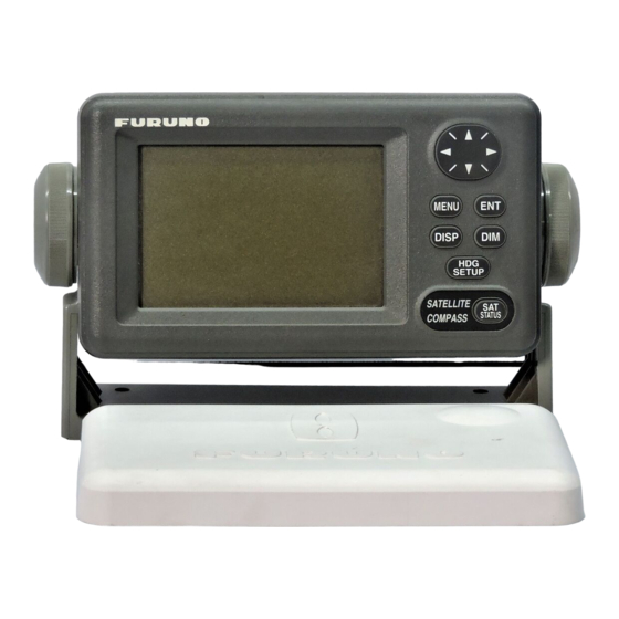
OPERATION Controls MENU key: Opens menu. Omnipad: Selects menu items; shifts cursor. DISP key: Selects display; closes menu. MENU ENT key: Terminates key input. DISP DIM key: Adjusts panel illumination, display contrast. SETUP HDG SETUP key: Chooses heading SATELLITE COMPASS STATUS source. -
Page 30: Turning The Power On/Off
2. OPERATION Turning the Power On/Off Use the power switch on the processor unit to turn the power to the display unit on and off. POWER Switch Processor unit A beep sounds and the display starts up with the last-used display. Note: If backup heading data is used the heading indication flashes until faithful heading data becomes available. -
Page 31: Choosing A Display
2. OPERATION Choosing a Display Use the DISP key to show a display desired. 2.4.1 Description of displays Heading display The heading display shows heading, course, speed, date, time and position-fixing status. The heading status mark changes in the sequence shown below. - Page 32 2. OPERATION Steering display The steering display shows heading in digital and analog form. SOG and COG are also indicated. Note that COG accuracy is low when the own ship speed is low. The faster the speed, the more accurate the COG. 07:54 Lubber's mark Bearing...
- Page 33 2. OPERATION Speed display Depending on the setting of DISTANCE DISP on the TRIP menu, the Set and Drift display or the Distance Run display is shown. The current indication requires a Doppler Speed Log. Ground speed Lateral speed Speed relative to °...
-
Page 34: Alarm Setup
2. OPERATION Alarm Setup The SC-50S can alert you with audible and visual alarms when GPS signal, DPGS signal and WAAS signal are lost. To set the DGPS alarm, do the following: 1. Press the MENU key to show the menu. -
Page 35: Confirming Satellite Status
2. OPERATION Confirming Satellite Status You can check the receiving condition of each antenna unit as follows: 1. Press the MENU key to open the menu. 2. Choose SATELLITE and then press the ENT key. RX signal level Horizontal bar extends with signal strength. -
Page 36: Gps Setup
2. OPERATION GPS Setup The GPS SETUP menu smoothes position and course, averages speed, applies position offset, and deactivates unhealthy satellites. 2.7.1 Displaying the GPS setup menu 1. Press the MENU key to open the menu. 2. Choose GPS SETUP and then press the ENT key. GPS SETUP SMOOTH POS 0SEC... -
Page 37: Output Data
2. OPERATION DISABLE SV (Disable satellite) Every GPS satellite is broadcasting abnormal satellite number(s) in its Almanac, which contains general orbital data about all GPS satellites. Using this information, the GPS receiver automatically eliminates any malfunctioning satellite from the GPS satellite schedule. However, the Almanac sometimes may not contain this information. - Page 38 GLL: Geographic position, latitude/longitude VHW: Water speed and heading VBW: Dual ground/water speed HVE: GPS antenna up-down motion amplitude (FURUNO proprietary sentence) ZDA: Time and date 7. Use the Omnipad to choose OFF or ON as appropriate and then press the ENT key.
- Page 39 2. OPERATION 11. Use the Omnipad to choose the baud rate of the equipment connected and then press the ENT key. 12. INTERVAL is selected; press the ENT key. 25ms 100ms 200ms Tx interval options 13. Use the Omnipad to choose appropriate output interval and then press the ENT key.
- Page 40 2. OPERATION Output sentence limitation The number of sentences which can be output depends on baud rate and output interval settings. The maximum number of characters per each data sentences are shown in the table below and the total number of characters must satisfy the formula shown below.
-
Page 41: Log Pulse
2. OPERATION 2.8.2 Log pulse This equipment provides SOG (speed over ground) in high accuracy. It converts an SOG value to a pulse signal and outputs at the rate of 200 or 400 pulses/nm. 1. Press the MENU key. 2. Choose I/O SETUP and then press the ENT key. 3. -
Page 42: System Setup
2. OPERATION System Setup 2.9.1 Geodetic data Your unit is preprogrammed to recognize most of the major chart systems of the world. Although the WGS-84 system (default setting) is the GPS standard, other categories of charts in other datum still exist. Match the GPS datum with the chart system you use. -
Page 43: Units Of Measurement
2. OPERATION 2.9.2 Units of measurement Distance/speed can be displayed in nautical miles/knots, kilometers/kilometers per hour, or miles/miles per hour. 1. Press the MENU key to open the menu. 2. Choose SYS SETUP and then press the ENT key. 3. Choose UNITS. 4. -
Page 44: Demonstration Mode
2. OPERATION 2.9.5 Demonstration mode The demonstration mode provides simulated operation of the equipment. 1. Press the MENU key to open the menu. 2. Choose SYS SETUP and then press the ENT key. 3. Choose DEMO and then press the ENT key. 4. -
Page 45: Waas/Dgps Setup
2. OPERATION 2.10 WAAS/DGPS Setup 1. Press the MENU key to open the menu. 2. Choose WAAS/DGPS and then press the ENT key. STATION: Shows GOOD or NG. WAAS/DGPS DATA: Shows GOOD or NG. SIG. S: Signal Strength. A figure be tween 0 MODE and 99 is shown. - Page 46 2. OPERATION 2) Use the Omnipad to choose WAAS satellite search method, AUTO or MANUAL as appropriate. For MANUAL, press the ENT key, enter appropriate WAAS satellite referring to the illustration below and then press the ENT key. Provider GEO Satellite Longitude POR (134) 178°E...
- Page 47 2. OPERATION 3) FREQ is selected; press the ENT key. 4) The cursor is selecting the hundredths digit so press ▲ or▼ to display appropriate digit. Press ► to shift the cursor to the tenths place. 5) Set other digits appropriately. 8.
-
Page 48: Others Menu
2. OPERATION 2.11 OTHERS Menu The OTHERS menu contains the following items: HOLD HDG DATA: Choose whether to display last-used heading data at power on or not. Because this data is not reliable, the heading indication flashes to alert you. HDG RESTORATION: Choose how to restore GPS signal, automatically or manually, after it is lost. -
Page 49: Trip Menu
2. OPERATION 2.12 TRIP Menu The TRIP menu functions to • Choose the indication to show on the SOG/STW display • Choose source of distance run • Reset distance run to zero • Smooth the tide drift indication • Enter smoothing for rate of turn and display range scale 1. -
Page 50: Resetting Distance Run
2. OPERATION 2.13 Resetting Distance Run The distance run may be reset to zero as below when the source of distance run is GPS or VBW. 1. Press the MENU key to display the main menu. 2. Choose TRIP MENU and then press the ENT key. 3. -
Page 51: Maintenance, Troubleshooting
MAINTENANCE, TROUBLESHOOTING WARNING ELECTRICAL SHOCK HAZARD Do not open the equipment. Only qualified personnel should work inside the equipment. Preventive Maintenance Regular maintenance is important for good performance. A maintenance program should be established and should include the following points. •... -
Page 52: Troubleshooting
Heading output from Connection between Firmly fasten the SC-50S does not appear SC-50S and external connector. on external equipment. equipment has loosened. Sensor trouble Run the diagnostic test1 to determine the cause. -
Page 53: Diagnostics
3. MAINTENANCE, TROUBLESHOOTING Diagnostics Diagnostic test1 The diagnostic test1 checks the equipment for proper operation. Note: Heading is not output during the diagnostic test, and this is communicated with an appropriate message. After completing the diagnostic test, turn the power off and on to update heading data. 1. - Page 54 3. MAINTENANCE, TROUBLESHOOTING ROM, RAM, KEY TEST OK shown for normal; ROM RAM NG (No Good) shown for error GPS1 PUSH KEY GPS receiver GPS2 KEY TEST GPS3 Press each key one by Processor unit one. Pressed key's name Display unit DISP appears here if key is functioning properly.
- Page 55 3. MAINTENANCE, TROUBLESHOOTING Diagnostic test2 If the heading indication changes randomly when ship is at anchor or does not change when the ship moves, run the test2 following the procedure below, with the ship at anchor and satellite signal received. Note: Heading is not output during the diagnostic test, and this is communicated with an appropriate message.
- Page 56 3. MAINTENANCE, TROUBLESHOOTING Diagnostic test3 This test checks the buzzer signal/contact for proper operation. 1. Press the MENU key to open the menu. 2. Choose SYS SETUP and then press the ENT key. 3. Choose TEST? and then press the ENT key. TEST1 TEST2 TEST3...
-
Page 57: 3.4 Program Number
3. MAINTENANCE, TROUBLESHOOTING 3.4 Program Number You may display the program number as follows: 1. Press the MENU key to open the menu. 2. Choose SOFT VER. and then press the ENT key. SOFTWARE VERSION DISPLAY 205-1342-**.** PROCESS 205-1341-**.** GPS1 4850263*** GPS2 4850263***... -
Page 58: Replacement Of Battery
3. MAINTENANCE, TROUBLESHOOTING Replacement of Battery The processor unit has a battery which stores data when the power is turned off. When the battery voltage is low, the message “BATTERY!” appears on the display. Have a qualified technician replace the battery, following the procedure below. -
Page 59: Replacement Of Fuse
3. MAINTENANCE, TROUBLESHOOTING Replacement of Fuse The 3 A fuse on the POWER Board inside the processor unit protects the equipment from overcurrent and reverse polarity of the power supply. If the power cannot be turned on, have a qualified technician check the fuse. WARNING Use the proper fuse. - Page 60 3. MAINTENANCE, TROUBLESHOOTING Error messages (con’t from previous page) Error Message Meaning Remedy BATTERY ALM! Voltage of battery in processor Have battery replaced at unit is low. earliest convenience. DATA ERR! GPS data (from the GPS receiver Check GPS receiver. in the processor unit) is lost for one minute.
-
Page 61: Appendix
APPENDIX APPENDIX Menu Tree BUZZER (SHORT, LONG , CONSTANT) ALARMS MENU DGPS ( OFF , ON) MESSAGES SMOOTH POS (0 SEC) GPS SETUP SMOOTH S/C (5 SEC) LAT OFFSET (0.000'N) LON OFFSET (0.000'E) DISABLE SV DATUM ( WGS84 , WGS72, OTHER 001 (WGS84)) SYS SETUP UNITS ( kt , km/h, mi/h) TIME DIFF (+00:00) -
Page 62: Geodetic Chart Codes
APPENDIX Geodetic Chart Codes 001• F WGS84 087• F MAPARIMA, BWI • F Trinldad and Tobago 002• F WGS72 088• F NORTH AMERICAN 1927 • F Western United States 003• F TOKYO • F Mean Vallue (Japan, Korea, and Okinawa) 089•... -
Page 63: Principle Of Satellite Compass
Difference in range between A1 and A2 is ∆λ + nλ where λ is 19 cm. “n” is automatically found during the initialization stage by receiving three satellites. A fraction of a carrier wavelength, ∆λ, is processed by FURUNO’s advanced kinematic technology in geographical survey, thus determining a vector (range and orientation) A1 to A2. -
Page 64: What Is Waas
SBAS signal. FURUNO will accept no responsibility for the use of the signal for other than the above stated purpose. It is the user’s responsibility to exercise common prudence and navigational judgment while using... -
Page 65: Index
INDEX Alarms menu .......... 2-6 Maintenance battery replacement ......3-8 cleaning ..........3-1 Battery replacement ....... 3-8 fuse replacement ........ 3-9 Menu tree ..........2 Compass display ........2-4 Control description ......... 2-1 Nav data display ........2-3 Data clearing .......... 3-7 OTHERS menu........
Need help?
Do you have a question about the SC-50S and is the answer not in the manual?
Questions and answers