Table of Contents
Advertisement
Quick Links
Advertisement
Table of Contents
Troubleshooting

Related Manuals for Furuno SC-120


Summary of Contents for Furuno SC-120
- Page 1 SATELLITE COMPASS SC-120...
- Page 2 Printed in Japan Printed in Japan All rights reserved. All rights reserved. PUB.No. OME-72490 PUB.No. OME-72490 ( ( KAMI KAMI ) ) SC-120 SC-120 Your Local Agent/Dealer Your Local Agent/Dealer FIRST EDITION : FIRST EDITION : MAR. MAR. 2001 2001 : : FEB.
-
Page 3: Safety Instructions
Immediately turn off the power at the switchboard if the equipment is emitting smoke or fire. Continued use of the equipment can cause fire or electrical shock. Contact a FURUNO agent for service. Do not place liquid-filled containers on the top of the processor unit. -
Page 4: Table Of Contents
3.3 Panel Illumination, Display Contrast... 3-2 3.4 Choosing a Display... 3-3 3.4.1 Description of displays... 3-3 3.5 Alarms... 3-5 3.6 Confirming Satellite Status ... 3-6 3.7 GPS Setup ... 3-7 3.7.1 Displaying the GPS setup menu... 3-7 3.7.2 GPS SETUP menu description... 3-7... - Page 5 3.8 Output Data... 3-8 3.8.1 Heading ... 3-8 3.8.2 Navigation data ... 3-9 3.8.3 Interface ... 3-9 3.8.4 Log pulse...3-10 3.8.5 Talker identifier mnemonics ...3-10 3.9 System Setup... 3-11 3.9.1 Geodetic data ... 3-11 3.9.2 Units of measurement ...3-12 3.9.3 Using local time...3-12 3.9.4 Time format ...3-12 3.9.5 Demonstration mode...3-13 3.10 DGPS Setup...3-13...
-
Page 6: Foreword
A Word to the Owner of the SC-120 FURUNO Electric Company thanks you for purchasing the FURUNO SC-120 Satellite Compass. We are confident you will discover why the FURUNO name has become synonymous with quality and reliability. For over 50 years FURUNO Electric Company has enjoyed an enviable reputation for quality and reliability throughout the world. -
Page 7: System Configuration
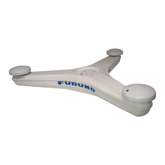
SYSTEM CONFIGURATION The SC-120 consists of three SC-series antennas, a display unit and a processor unit. The tri-antenna system helps reduce the influence of ship's motion (rolling). DGPS Beacon Antenna GR-800-1-S Beacon Receiver Kit Processor Unit Speed alarm/ SC-1201/SC-1201D Heading alarm... -
Page 8: Equipment List
EQUIPMENT LIST Standard supply Name Type Antenna Unit SC-1203F DGPS GR-800-SC-1-S Antenna Display Unit SC-602 SC-1201 Processor Unit SC-1201-D CP20-02210 CP20-02203 Installation Materials CP20-02220 Accessories FP14-02801 Spare Parts SP20-00901 Optional equipment Name Type MJ-A6SPF0003-050 MJ-A6SPF0007-100 Cable Assy. MJ-A6SPF0012-100 MJ-A7SPF0003-050 CP20-01700 Antenna Cable Set CP20-01710... -
Page 9: Software Version List
SOFTWARE VERSION LIST DISPLAY UNIT: 205-1312-009 PROCESSOR UNIT: 205-1311-016 GPS1: 205-1313-004 GPS2: 205-1313-004 GPS3: 205-1313-004 DGPS: 085-0182-002... - Page 10 This page is intentionally left blank.
-
Page 11: Specifications
1575.42 MHz (L1) Standard Positioning service (SPS) using the C/A code on the L1 frequency All-in-view, 8-state Kalman filter 10 m (GPS), or 5 m (DGPS), 95% of the time ±0.6° (95% static accuracy) 25°/s rate-of-turn 4 minutes 4.5 inch monochrome LCD, 120 x 64 dots... - Page 12 IMO A. 694(17) General requirements IEC 60945 version 4 General requirements (EMC tested to 2 GHz) IMO A.819 (19) Performance standard for shipborne GPS IEC 61108-1 Performance standard for shipborne GPS ITU-R M.1371 for AIS Rate of turn Sentences: MSK, GGA 12-24 VDC: 1.1-0.5 A...
-
Page 13: Principle Of Operation
In reality, a third antenna is used to reduce the influence of pitch, roll and yaw, and five satellites are processed to obtain 3D data. If the GPS signal is blocked by a tall building or the vessel is under a bridge, the 3-axis solid-state angular rate gyros in the processor unit take place of the satellite compass, maintaining the current heading continuously. - Page 14 This page is intentionally left blank.
-
Page 15: Installation
INSTALLATION Mounting Considerations 2.1.1 SC-series antenna unit General Keep the length of antenna cable in mind when selecting a mounting location. The cable comes in lengths of 15 meters (standard supply), or 30 m or 50 m (optional lengths). Select a location where vibration and shock are minimal. Installing the antenna above superstructures The antenna must be mounted above all other structures on the vessel to obtain an unobstructed view of the satellites regardless of vessel heading. - Page 16 2. INSTALLATION The horizontal separation between the antenna and masts must be as follows: Mast diameter Separation distance (minimum) 10 cm 30 cm Keep the length of antenna cable in mind when selecting a mounting location. The cable comes in lengths of 15 meters (standard supply), or 30 m or 50 m (optional lengths).
-
Page 17: Display Unit, Processor Unit
Locate the antenna above the radar antenna, out of the radar beam. Sc-series Antenna Example of improper installation Location influenced by reflected wave. NO! UNSUITABLE LOCATION SC-series antenna located below all other structures 2.1.2 Display unit, processor unit Choose a location where vibration and shock are minimal. Install the units well away from locations subject to rain and water splash. -
Page 18: Installing The Antenna Units
2. INSTALLATION Installing the Antenna Units 2.2.1 SC-series antenna unit 1. Prepare an installation post for the antenna in accordance with the illustration shown below. Recommended Flange (Option) Name: Flange Type: OP20-31 Code No.: 004-378-230 Weld all the way around. Post should be constructed from stainless steel and measure 4mm or larger in thickness. - Page 19 2. Fix the antenna unit to the post as shown below. Set the antenna unit to the flange. Flat washer Spring washer (Torque: 29.58 Nm) Fastening antenna unit to a post 3. Coat each nut, bolt and washer with silicone rubber for waterproofing. Coating bolt, nut and washer with silicone rubber Fix the antennas #1 and #2 on the fore-and-aft line of the ship,...
- Page 20 2. INSTALLATION 4. As shown below, make a loop in the antenna cable and fasten the antenna cable to the antenna post with two cable ties. Coat with Three Bond 1211 (supplied). 5. Coat bolt threads with Three Bond 1211. Fasten bolts with nuts.
-
Page 21: Dgps Antenna Unit
Choose a mounting location for the DGPS antenna considering the points mentioned below. DPGS is not necessary for heading determination, however it can improve the accuracy of GPS position fixing Separate the DGPS antenna at least three meters from a radio antenna. - Page 22 2. INSTALLATION 4. The DGPS antenna is supplied with a 15 m cable. If extension is necessary use the extension cable (option). Cover the extension connectors with vulcanizing tape and vinyl tape, for waterproofing. Tie tape ends with a cable tie.
-
Page 23: Installing The Processor Unit
Installing the Processor Unit The processor unit should be mounted aligned with the ship’s fore-and-aft line. It can be mounted on the deck, bulkhead, or on the underside of a desk. Choose a mounting location which allows you to easily view the power lamp on the top of the unit and which is within 2.5 of the ship’s fore-and-aft line. -
Page 24: Bulkhead Mount
2. INSTALLATION 2.3.2 Bulkhead mount For mounting on a bulkhead, use the bulkhead mounting plate supplied with the installation materials. 1. Unfasten four screws from the top cover to open the front panel. 2. Unfasten two screws to dismount the angular rate sensor. 3. - Page 25 4. Loosen four screws on the angular rate sensor mounting base, and then fasten the bulkhead mounting plate to the angular rate sensor mounting base. Angular Rate Sensor Angular Rate Sensor Mounting Base 5. Close the top cover of the processor unit. 6.
-
Page 26: Installation On The Underside Of A Desk
2. INSTALLATION The unit can be oriented as shown in the figure below. After the unit is installed you will specify the mounting method from the menu. Mounting Method: "Wall" Mounting Direction: D 7. Fasten the ground wire between the ground terminal on the processor unit and the ship’s superstructure. - Page 27 The reference direction is as shown below. The mounting method is the same as that for mounting on the deck. Reference Direction Mount processor unit so reference direction is within ± 2.5 of fore-and-aft line. POWER switch (power lamp) Processor Unit, rear view Mounting Method: Invert Mounting Direction: A Starboard...
-
Page 28: Adjusting For Orientation Error
2. INSTALLATION 2.3.4 Adjusting for orientation error It may be impossible to perfectly align the processor unit on the fore-and-aft or port-and-starboard line. Open the top cover, loosen the two fixing screws on the angular rate sensor and turn. For example, if the orientation error is 2.5 to port, rotate the sensor 2.5 starboard The range of adjustment is -45 to +45 Close the top cover after completing the adjustment. -
Page 29: Flush Mounting
2.4.2 Flush mounting Two types of flush mounts are available. See the outline drawing at the back of the manual for details. Flush mount “F” Flush mount “F” kit Name Cosmetic Panel Tapping Screw Hex Bolt Spring Washer 1. Make a cutout in mounting location. The dimensions are 183(W) x 92(H) mm. 2. -
Page 30: Wiring
General wiring diagram TPPX6-3D2V-15M No color Yellow ANTENNA UNIT SC-1203F Cable Tie (Long life, temperature resistant, local supply) DGPS ANTENNA GR-800-1-S TNC-PS-3D (15 m) 12-24 VDC MJ-A3SPF0013-035, 3.5 m Port on Processor Unit GPS ANT 1 GPS ANT 2 GPS ANT 3... - Page 31 Note 1: Instead of TPPX6-3D2V, three Japan Industrial Standard coaxial cables 3D2V (local supply) or equivalent can be used as antenna cables. 3D2V Sectional view of coaxial cable 3D2V Note 2: The optional antenna cable set (CP20-01700 or CP20-01710, 3 sets) allows you to extend the antenna cable to 30 m or 50 m.
- Page 32 2. INSTALLATION How to attach connector N-P-8DFB Outer Sheath Armor Inner Sheath Shield Cover with heat-shrink tubing and heat. Clamp Nut Gasket Connect the DGPS antenna cable to the BEACON ANT port on the processor unit. The standard cable is 15 m long. With the optional extension cable the cable can be extended to 30 m or 60 m.
-
Page 33: Initial Settings
"RATE ERROR." Be sure to enter correct data. MAIN MENU SATELLITE ALARMS DGPS MESSAGES I/O SETUP GPS SETUP INST MENU SYS SETUP ERASE SOFT VER. TRIP MENU OTHERS Main menu ) to choose “INST MENU” and press the [ENT] key. -
Page 34: Choosing Heading Source
2. Use the Omnipad to choose HEADING. 3. Press the [ENT] key. 4. Choose INT or EXT as appropriate. Normally choose INT. If the GPS sensor is not working and a heading sensor such as a gyrocompass is available, choose EXT. -
Page 35: Heading Data Format
Note: When switching from internal heading to external heading when using an autopilot in the auto mode, set the autopilot in the manual mode BEFORE switching, adjust heading at the autopilot and then switch to the auto mode. 5. Press the [ENT] key. 6. -
Page 36: Connection Of External Equipment
Cable: MJ-A7SPF0003-050 (option) Output: Log Pulse. Cable: MJ-A7SPF0003-050 (option) BEACON DISPLAY LOG/ALARM GPS ANT Input: Heading Sensor*, Gyrocompass* in AD-10 Format, NMEA 0183 (IEC 61162) Doppler Speed Log/Current Indicator in NMEA0183 (IEC 61162) Cable: MJ-A6SPF0003-100 (Option) MJ-A6SPF0007-100 (Option) MJ-A6SPF0012--050 (Option) External heading input format and output sentence AD-10: Header of IEC 61162 data sentence chosen on menu is output. - Page 37 Procedure 1. Open the top cover processor unit. 2. Open the cover of the DGPS receiver assembly. 3. Connect the cable TNCBPJ(140) to J1 on the DGPS receiver assembly. 4. Remove the plug at the rear of the processor unit. 5.
- Page 38 2. INSTALLATION 9. Fix the PH connector assy. with a clamp as shown in the illustration below. Pass PH connector through clamp DGPS Receiver Assy. 10. Close the top cover of the processor unit. 11. Mount the DGPS antenna and whip antenna, referring to section 2.2. 2-24 Processor unit, cover removed, top view...
-
Page 39: Operation
OPERATION Controls HOW TO REMOVE THE COVER Press here and pull toward you to remove cover. Reduced accuracy may occur in case of unfavorable satellite constellation, worsened HDOP, etc. Always confirm position against other navigation devices to verify reliability. Omnipad: Selects menu items; shifts cursor. -
Page 40: Turning The Power On/Off
Use the power switch on the processor unit to turn the power on and off. The display starts up with the last-used display. Note 1: Turn on external equipment AFTER the SC-120 is showing reliable heading data, to prevent heading output error. -
Page 41: Choosing A Display
The heading status mark changes in the sequence shown below. The “final calculations” mark disappears after heading becomes reliable, which is approximately 90 seconds after that mark appears. Position-fixing status indications 2D GPS position fix 3D GPS position fix 2D DGPS position fix 3D DGPS position fix... - Page 42 3. OPERATION Steering display The steering display mainly shows heading, in digital and analog form. The own ship mark points to heading on the bearing scale. Bearing scale Compass display The compass display shows heading by compass direction, pitch and roll The compass rose rotates with heading.
-
Page 43: Alarms
Alarms The SC-120 can alert you with audio and visual alarms when GPS data and DGPS data are lost. To set the alarm mode; 1. Press the [MENU] key to show the menu. 2. Choose ALARMS and press the [ENT] key. -
Page 44: Confirming Satellite Status
3. OPERATION Press the [ENT] key. 7. Select appropriate option. For HDG BACKUP, use ▲ or ▼ on the Omnipad to set time, from 1 to 5 (minutes). 8. Press the [ENT] key. 9. Press the [DISP] key to close the menu. Confirming Satellite Status You can check the receiving condition of each antenna element as follows: 1. -
Page 45: Gps Setup
GPS fix may change randomly, even if the vessel at anchor. This change can be smoothed by averaging a number of GPS fixes. The setting range is from 0 (no smoothing) to 999 seconds. The setting range is from 0 (no smoothing) to 999 seconds, and the default is 5 s, which is good for rolling period o 5-8 s. -
Page 46: Output Data
3. OPERATION information, the GPS receiver automatically eliminates any malfunctioning satellite from the GPS satellite schedule. However, the Almanac sometimes may not contain this information. If you hear of an inoperative satellite you can disable it manually. Enter satellite number in two digits and press the [ENT] key. -
Page 47: Navigation Data
2. Choose I/O SETUP and press the [ENT] key. 3. Choose “NAV OUT?” and press the [ENT] key. VTG: Course over ground and ground speed GGA: Global positioning system (GPS) fix data ZDA: Time and date ATT: True heading, pitching, rolling... -
Page 48: Log Pulse
3. Choose HDG TALKER and press the [ENT] key. 4. Choose GP, HE, HN or HC as appropriate and press the [ENT] key. Choose GP normally. If an external gyrocompass is to be used, choose HC. GP: GPS Navigator HE: North-seeking gyrocompass HN: Non-north seeking gyrocompass HC: Gyrocompass 5. -
Page 49: System Setup
Your unit is preprogrammed to recognize most of the major chart systems of the world. Although the WGS-84 system (default setting) is the GPS standard, other categories of charts in other datum still exist. Match the GPS datum with the chart system. -
Page 50: Units Of Measurement
7. Press the [DISP] key to close the menu. 3.9.3 Using local time GPS uses UTC time. If you would rather use local time, enter the time difference (range: -13:30 to +13:30) between local time and UTC. 1. Press the [MENU] key to open the menu. -
Page 51: Demonstration Mode
3.9.5 Demonstration mode The demonstration mode provides simulated operation of the equipment. 1. Press the [MENU] key to open the menu. 2. Choose SYS SETUP and press the [ENT] key. 3. Choose DEMO and press the [ENT] key. 4. Choose ON or OFF as appropriate and press the [ENT] key. 5. - Page 52 GPS position. Note: When connecting a FURUNO external DGPS beacon receiver (such as the GR-80) to the SC-120, turn the GR-80’s remote function on to set up the beacon receiver with commands from the SC-120. Also set the external DGPS beacon receiver as follows: Byte Format, 8-6;...
-
Page 53: Programming User Beacon Stations
LIST a) The following display appears after pressing the [ENT] key at step 7. [EXIT] 310.0 287.0 292.0 321.0 302.0 Beacon station frequency b) Choose desired station with the Omnipad. c) Press the [ENT] key. 8. Press the [DISP] key to close the menu. 3.10.2 Programming user beacon stations The user may program 20 DGPS beacon stations from which to use in selection... -
Page 54: Editing User Beacon Stations
3. OPERATION Note: For steps 7-10 use the Omnipad to enter data. Choose location with ◄ or ►; change value with ▲ or ▼. 7. Press the [ENT] key, enter frequency of the station, and press the [ENT] key. 8. Press the [ENT] key, enter baud rate of the station, and press the [ENT] key. 9. -
Page 55: Erasing Individual User Stations
3.10.4 Erasing individual user stations 1. Press the [MENU] key to open the menu. 2. Choose DGPS and press the [ENT] key. 3. Choose STATION and press the [ENT] key. 4. Choose LIST and press the [ENT] key. 5. Choose USER and press the [ENT] key. 6. -
Page 56: Others Menu
11. Choose the range of the ROT graph: 30, 60 or 90 and press the [ENT] key. 12. Press the [DISP] key to close the menu. 3-18 MAIN MENU SATELLITE ALARMS DGPS MESSAGES I/O SETUP GPS SETUP INST MENU SYS SETUP ERASE SOFT VER. TRIP MENU OTHERS Main menu OTHERS HOLD HDG DATA: SMOOTH ROT : 2.5SEC... -
Page 57: Trip Menu
(DRIFT). Press the [ENT] key. 3. Choose DISTANCE CALC and press the [ENT] key. 4. Choose the source for distance run; GPS, VLW (distance traveled through water) or VBW (Dual ground/water speed). (VLW requires DS-80 type Doppler speed log and VBW requires Current indicator or Doppler speed log.) Press the [ENT] key. - Page 58 This page is intentionally left blank.
-
Page 59: Maintenance, Troubleshooting
MAINTENANCE, TROUBLESHOOTING Preventive Maintenance Regular maintenance is important for good performance. A maintenance program should be established and should include the following points. Check connectors and ground terminal on the processor unit and display unit for tightness. Check ground terminal for rust. Clean or replace as necessary. Check for water leakage in the antenna cable. -
Page 60: Troubleshooting
Heading output from SC-120 does not appear on external equipment. If large hading error occurs or heading indication is frequently interrupted, contact your dealer for advice. Diagnostics Diagnostic test1 The diagnostic test checks the equipment for proper operation. - Page 61 5. Press ◄ to choose YES and press the [ENT] key. The test proceeds in the sequence shown below. OK shown for normal; NG (No Good) shown for error GPS1 GPS receiver GPS2 GPS3 Processor unit Display unit DISP Internal beacon receiver...
- Page 62 4. MAINTENANCE, TROUBLESHOOTING Diagnostic test2 If the heading indication changes randomly when ship is at anchor or does not change when the ship moves, run the test2 following the procedure below, with the ship at anchor and satellite signal received. Note: Heading is not output during the diagnostic test, and this is communicated with an appropriate message.
-
Page 63: Program Number
3. Press the [DISP] key to close the program version no. display. Clearing Data You may clear GPS data and system data all at once or individually as follows: 1. Press the [MENU] key to open the menu. 2. Choose ERASE and press the [ENT] key. -
Page 64: Replacement Of Battery
4. MAINTENANCE, TROUBLESHOOTING Replacement of Battery The display unit and processor unit have a battery which stores data when the power is turned off. When the battery voltage is low the message “BATTERY!” appears on the display. Open the message display, by pressing the [MENU] key and choosing “MESSAGES”, to find out which battery’s voltage is low. -
Page 65: Replacement Of Fuse
1. Press the [MENU] key to open the menu. 2. Choose MESSAGES and press the [ENT] key. 3. Press the [DISP] key to close the menu. Error Message ABORTING! GPS heading error continues for one minute. For example, satellite cannot be acquired because of unfavorable environment. ABORTING CALC! - Page 66 BATTERY Voltage of battery in processor ALM!(PRCSSR) unit is low. DATA ERR! GPS data (from the GPS receiver in the processor unit) is lost for one minute. Heading output is stopped and the heading indication shows “- - -“. DGPS ERROR!
-
Page 67: Appendix
SYSTEM DATA? ALL BACKUP DATA? HOLD HDG DATA (OFF, ON) SMOOTH ROT (0.1 - 30.0, 2.5 (sec)) ° ROT RANGE (30, 60, 90 ( /min)) DISTANCE DISP (DSTNC, DRIFT) DISTANCE CALC (GPS, VLW, VBW ) RESET DISTANCE? DRIFT AVG. (0-9999SEC, 10) -
Page 68: Geodetic Chart Codes
APPENDIX Geodetic Chart Codes 001: WGS84 002: WGS72 003: TOKYO : Mean Value (Japan, Korea & 004: NORTH AMERICAN 1927 : Mean Value (CONUS) 005: EUROPEAN 1950 : Mean Value 006: AUSTRALIAN GEODETIC 1984 : Australia & Tasmania 007: ADINDAN : Mean Value (Ethiopia &... -
Page 69: Digital Interface
Max. Voltage: ±15 V Threshold: 4 mA (In case of connection of FURUNO device talker) Data transmission Data is transmitted in serial asynchronous form in accordance with the standard referenced in 2.1 of IEC 61162-1. The first bit is a start bit and is followed by data bits, least-significant-bit as illustrated below. - Page 70 APPENDIX Schematic diagrams HDG IN port (listener) Load requirements Isolation: Optocoupler Input Impedance: 220 ohm Max. voltage: ±15V HDG OUT1 port Output drive capability Max. 10 mA...
- Page 71 APPENDIX NAV OUT1 Port Output drive capability Max. 10 mA HDG4 NAV2 port RS-232C level...
- Page 72 PFECatt- True heading, pitching, rolling $PFEC,GPatt,xxx.x,+xx.x,-xx.x<CR><LF> $PFEC,GPatt,xxx.x,+xx.x,-xx.x*hh<CR><LF> GGA - Global positioning system (GPS) fix data Time, position and fix related data for a GPS receiver. Differential reference station ID, 0000-1023 Age of differential GPS data Units of geoidal separation, m...
- Page 73 This sentence is not used in the current version of NMEA and IEC 61162. Some boaters may want the GPS compass to indicate the magnetic heading when the boat is only fitted with a magnetic compass. HDG is calculated by adding a geomagnetic variation to HDT.
- Page 74 APPENDIX A VDR - Set and drift $--VDR,x.x,T,x.x,M,x.x,N*hh<CR><LF> | | | | | +--------- 4 | +--+----------- 3 | | +--+----------------- 2 +--+----------------------- 1 1. Direction, degrees true 2. Direction, degrees magnetic 3. Current speed, knots 4. Checksum VHW - Water speed and heading The compass heading to which the vessel points and the speed of the vessel relative to the water.
- Page 75 APPENDIX A VTG - Course over ground and ground speed COG and SOG obtained by processing the GPS signals. $GPVTG, x.x, T, x.x, M, x.x, N, x.x, K, p*hh<CR><LF> Positioning mode indicator* Speed, km/h Speed, knots Course degrees magnetic Course degrees true *A = Autonomous, D = Differential, E = estimated(dead reckoning), M = Manual input, S = Simulator, N = Data not valid.
-
Page 76: Input/Output Ports
GLL, ROT, ZDA (on/off by menu) 5) IEC 61162 (NMEA 0183) sentence output interval: 1 sec 6) ATT sentence Proprietary sentence or FURUNO sentence Only P sentence: output rate of 0.1 sec Accompanied with any of above sentences: ATT sentence – True heading, pitching, rolling $PFEC, Gpatt, xxx.x, +xx.x, +xx.x<CR><LF>... -
Page 77: Parts Location
LOG/ALARM HDG IN Note: Each GPS receiver GPS1, GPS2, and GPS3 calculates VTG/GGA/GLL/ZDA. The output from HDG OUT and NAV OUT ports is one calculated by the GPS1. However, when the GPS1 is defective, the GPS2 replaces it. When both GPS1 and GPS2 are defective, the data calculated by the GPS3 is used. -
Page 78: Parts List
This equipment contains complex modules in which fault diagnosis and repair down to component level are not practical (IMO A.694(17)/8.3.1. Only some discrete components are used. FURUNO Electric Co. Ltd. believes identifying these components is of no value for shipborne maintenance; therefore, they are not listed in this manual. Major modules can be located on the parts location photo on page A-5. -
Page 79: Packing Lists
PACKING LIST PACKING LIST PACKING LIST PACKING LIST SC-60/120 (J/E) SC-60/120 (J/E) SC-60/120 (J/E) SC-60/120 (J/E) N A M E ユニット ユニット ユニット ユニット UNIT UNIT UNIT UNIT 表示部 DISPLAY UNIT 付属品 付属品 ACCESSORIES ACCESSORIES 付属品 付属品 ACCESSORIES ACCESSORIES 保護カバー COVER 工事材料 工事材料 工事材料 工事材料 INSTALLATION MATERIALS INSTALLATION MATERIALS INSTALLATION MATERIALS INSTALLATION MATERIALS +トラスタッピンネジ... - Page 80 SC-1203F N A M E ユニット UNIT GPSアンテナ GPS ANTENNA 工事材料 INSTALLATION MATERIALS 鳥よけ BIRD-REPELLENT FIXTURE 六角ナット 1種 HEX.NUT 座金 WASHER スリーボンド SEALANT ガスケット GUSKET (略図の寸法は、参考値です。 DIMENSIONS IN DRAWING FOR REFERENCE ONLY.) DESCRIPTION/CODE № O U T L I N E...
- Page 81 工事材料表 工事材料表 工事材料表 工事材料表 INSTALLATION MATERIALS 番 号 名 称 NAME ケーブル組品 POWER CABLE ケーブル組品MJ CABLE ASSY. ケーブル組品MJ CABLE ASSY. (略図の寸法は、参考値です。 DIMENSIONS IN DRAWING FOR REFERENCE ONLY.) (略図の寸法は、参考値です。 DIMENSIONS IN DRAWING FOR REFERENCE ONLY.) (略図の寸法は、参考値です。 DIMENSIONS IN DRAWING FOR REFERENCE ONLY.) (略図の寸法は、参考値です。 DIMENSIONS IN DRAWING FOR REFERENCE ONLY.) CODE NO.
- Page 82 A−4...
- Page 83 A−5...
- Page 84 A−6...
- Page 85 GP-80,GP-90,SC-55,GP-3500/F 工事材料表 工事材料表 工事材料表 工事材料表 GP-1850,GP-1650,FA-100,GP-1640/F SC-60/120,GD/GP-280/680/380 INSTALLATION MATERIALS 番 号 名 称 NAME アンテナケーブル組品 ANTENNA CABLE ASSY. ケーブル組品 CABLE ASSY. (略図の寸法は、参考値です。 DIMENSIONS IN DRAWING FOR REFERENCE ONLY.) (略図の寸法は、参考値です。 DIMENSIONS IN DRAWING FOR REFERENCE ONLY.) (略図の寸法は、参考値です。 DIMENSIONS IN DRAWING FOR REFERENCE ONLY.) (略図の寸法は、参考値です。 DIMENSIONS IN DRAWING FOR REFERENCE ONLY.)...
- Page 86 工事材料表 工事材料表 工事材料表 工事材料表 INSTALLATION MATERIALS 番 号 名 称 NAME 変換ケーブル組品 CONVERT CABLE ASSY. ビニールテープ VINYL TAPE コネクタ(N) CONNECTOR 絶縁テープ SELF-BONDING TAPE (略図の寸法は、参考値です。 DIMENSIONS IN DRAWING FOR REFERENCE ONLY.) (略図の寸法は、参考値です。 DIMENSIONS IN DRAWING FOR REFERENCE ONLY.) (略図の寸法は、参考値です。 DIMENSIONS IN DRAWING FOR REFERENCE ONLY.) (略図の寸法は、参考値です。 DIMENSIONS IN DRAWING FOR REFERENCE ONLY.)...
- Page 87 Takahashi T Takahashi T...
-
Page 95: Index
DISP key ...3-3 Distance run display...3-4 Distance run resetting ...3-19 Error messages...4-6 Fuse replacement ...4-6 Geodetic chart codes ... A-2 Geodetic data...3-11 GPS setup menu...3-7 Heading display ...3-3 Heading setup menu...2-19 Illumination ...3-2 Local time ... 3-12 Log pulse ... 3-10 Maintenance battery replacement...
Need help?
Do you have a question about the SC-120 and is the answer not in the manual?
Questions and answers