Juniper SRX240 Hardware Manual
Srx240 services gateway
Hide thumbs
Also See for SRX240:
- Hardware manual (198 pages) ,
- Getting started manual (4 pages) ,
- Quick start manual (2 pages)

Related Manuals for Juniper SRX240


Summary of Contents for Juniper SRX240
-
Page 1: Hardware Guide
SRX240 Services Gateway Hardware Guide Published: 2013-10-17 Copyright © 2013, Juniper Networks, Inc. - Page 2 END USER LICENSE AGREEMENT The Juniper Networks product that is the subject of this technical documentation consists of (or is intended for use with) Juniper Networks software. Use of such software is subject to the terms and conditions of the End User License Agreement (“EULA”) posted at http://www.juniper.net/support/eula.html.
-
Page 3: Table Of Contents
SRX240 Services Gateway Description ........3... - Page 4 Preparing the SRX240 Services Gateway for Installation ....43 Installing the SRX240 Services Gateway ....... . 44 Replacing or Installing Mini-Physical Interface Modules in the SRX240 Services Gateway .
- Page 5 Chapter 15 Monitoring the SRX240 Services Gateway ......95 Monitoring Hardware Components on the SRX240 Services Gateway ..95 Monitoring the SRX240 Services Gateway Chassis Using the CLI .
- Page 6 Gateway ..........106 Juniper Networks Technical Assistance Center ......106...
- Page 7 DC Power Wiring Terminations Warning ......136 SRX240 Services Gateway Agency Approvals ......138 SRX240 Services Gateway Compliance Statements for EMC Requirements .
-
Page 8: Part 5 Index
SRX240 Services Gateway Hardware Guide Part 5 Index Index ............. 161 viii Copyright ©... -
Page 9: About This Guide
This guide is designed for network administrators who are installing and maintaining a Juniper Networks SRX240 Services Gateway or preparing a site for device installation. To use this guide, you need a broad understanding of networks in general and the Internet in particular, networking principles, and network configuration. - Page 10 SRX240 Services Gateway Hardware Guide Table 1: Notice Icons Icon Meaning Description Informational note Indicates important features or instructions. Caution Indicates a situation that might result in loss of data or hardware damage. Warning Alerts you to the risk of personal injury or death.
-
Page 11: Srx Series Documentation And Release Notes
If the information in the latest SRX Series Release Notes differs from the information in the documentation, follow the SRX Series Release Notes. Obtaining Documentation To obtain the most current version of all Juniper Networks technical documentation, see the products documentation page on the Juniper Networks website at http://www.juniper.net/techpubs To order printed copies of this guide and other Juniper Networks technical documents, contact your sales representative. -
Page 12: Documentation Feedback
7 days a week, 365 days a year. Self-Help Online Tools and Resources For quick and easy problem resolution, Juniper Networks has designed an online self-service portal called the Customer Support Center (CSC) that provides you with the following features: Find CSC offerings: http://www.juniper.net/customers/support/... -
Page 13: Opening A Case With Jtac
About This Guide Join and participate in the Juniper Networks Community Forum: http://www.juniper.net/company/communities/ Open a case online in the CSC Case Management tool: http://www.juniper.net/cm/ To verify service entitlement by product serial number, use our Serial Number Entitlement (SNE) Tool: https://tools.juniper.net/SerialNumberEntitlementSearch/ Opening a Case with JTAC You can open a case with JTAC on the Web or by telephone. - Page 14 SRX240 Services Gateway Hardware Guide Copyright © 2013, Juniper Networks, Inc.
-
Page 15: Srx240 Services Gateway Overview
SRX240 Services Gateway Overview Introduction to the SRX240 Services Gateway on page 3 SRX240 Services Gateway Hardware Components and Specifications on page 7 SRX240 Services Gateway Mini-Physical Interface Modules on page 23 SRX240 Services Gateway Power over Ethernet Support on page 25... - Page 16 SRX240 Services Gateway Hardware Guide Copyright © 2013, Juniper Networks, Inc.
-
Page 17: Introduction To The Srx240 Services Gateway
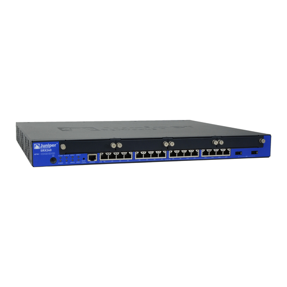
The SRX240 Services Gateway runs the Juniper Networks Junos operating system (Junos OS). The SRX240 Services Gateway has a modular 1U chassis that fits a 19-inch rack with a depth of approximately 17.5 in. (44.5 cm). Figure 1 on page 3 shows the SRX240 Services Gateway. -
Page 18: Srx240 Services Gateway Models
SRX240 Services Gateway Hardware Guide For information about SRX240 Services Gateway software features and licenses, see the following guides: Initial Configuration for Security Devices Monitoring and Troubleshooting for Security Devices Related SRX240 Services Gateway Chassis on page 7 Documentation SRX240 Services Gateway Models Table 3 on page 4 lists the SRX240 Services Gateway models. -
Page 19: Srx240 Services Gateway Hardware Features
Power, Mini-PIMs, Port (TX/RX/Link and Port (TX/RX/Link and Port (TX/RX/Link and PoE) PoE) PoE), DC power feed LEDs. NOTE: The PoE LED is enabled only on the PoE variant of the SRX240 Services Gateway. Copyright © 2013, Juniper Networks, Inc. - Page 20 NEBS-compliant NOTE: An air filter is not shipped with the SRX240 Services Gateway with AC power supply models. To meet NEBS requirements, you must order the air filter separately and install it. Contact your Juniper Networks customer service representative for more information.
-
Page 21: Srx240 Services Gateway Hardware Components And Specifications
This chapter includes the following topics: SRX240 Services Gateway Chassis on page 7 SRX240 Services Gateway Front Panel and Back Panel Views on page 9 SRX240 Services Gateway Built-In Interfaces on page 12 SRX240 Services Gateway LEDs on page 14... - Page 22 Value Chassis depth 15 in. (38.1 cm) Chassis weight SRX240 Services Gateway with AC power supply and no PoE support models: 11.24 lb. (5.1 kg) SRX240 Services Gateway with AC power supply and PoE support models: 12.34 lb. (5.6 kg) SRX240 Services Gateway with DC power supply models: 12.56 lb.
-
Page 23: Srx240 Services Gateway Front Panel And Back Panel Views
SRX240 Services Gateway Cooling System on page 21 SRX240 Services Gateway Front Panel and Back Panel Views This topic describes the front panel and back panel of the SRX240 Services Gateway models. This topic includes the following sections: SRX240 Services Gateway Front Panel on page 9... - Page 24 For more information on the front panel components, see the following topics: SRX240 Services Gateway Built-In Interfaces on page 12 SRX240 Services Gateway LEDs on page 14 SRX240 Services Gateway Boot Devices and Dual-Root Partitioning Scheme on page 18 Copyright © 2013, Juniper Networks, Inc.
-
Page 25: Srx240 Services Gateway Back Panel (Ac Power Supply Models)
The air filter is shipped with SRX240 Services Gateways with DC power supply models only. You can order the air filter separately for the SRX240 Services Gateway with AC power supply models. Contact your Juniper Networks customer service representative for more information. -
Page 26: Srx240 Services Gateway Built-In Interfaces
SRX240 Services Gateway Built-In Interfaces on page 12 SRX240 Services Gateway LEDs on page 14 SRX240 Services Gateway Boot Devices and Dual-Root Partitioning Scheme on page 18 SRX240 Services Gateway Power Supply on page 20 SRX240 Services Gateway Cooling System on page 21... - Page 27 Related SRX240 Services Gateway Chassis on page 7 Documentation SRX240 Services Gateway Front Panel and Back Panel Views on page 9 SRX240 Services Gateway LEDs on page 14 SRX240 Services Gateway Boot Devices and Dual-Root Partitioning Scheme on page 18...
-
Page 28: Srx240 Services Gateway Leds
This topic includes the following sections: Front Panel LEDs on page 14 Ethernet Port LEDs on page 16 DC Power Supply Feed LEDs (SRX240 Services Gateway DC Power Supply Model) on page 17 Front Panel LEDs Figure 6 on page 14 shows the SRX240 Services Gateway front panel LEDs. - Page 29 Chapter 2: SRX240 Services Gateway Hardware Components and Specifications Table 10: SRX240 Services Gateway Front Panel Components (continued) Component Description Usage Alarm LED The Alarm LED has the following The Alarm LED can be used to indicator colors: gather information on major or minor...
-
Page 30: Ethernet Port Leds
SRX240 Services Gateway Hardware Guide Ethernet Port LEDs On the SRX240 Services Gateway, each Gigabit Ethernet port has the two LEDs as shown Figure 7 on page Figure 7: SRX240 Services Gateway Port LEDs Table 11: SRX240 Services Gateway Port LEDs... -
Page 31: Dc Power Supply Feed Leds
DC Power Supply Feed LEDs (SRX240 Services Gateway DC Power Supply Model) On the SRX240 Services Gateway with DC power supply models, the back panel includes two LEDs, which indicate the status of the DC power supply feed. Figure 8 on page 17 shows the DC power supply feed LEDs on the SRX240 Services Gateway with DC power supply model. -
Page 32: Srx240 Services Gateway Boot Devices And Dual-Root Partitioning
Boot Devices on page 18 Dual-Root Partitioning Scheme on page 19 Boot Devices The SRX240 Services Gateway can boot from the following storage media (in the given order of priority): Internal NAND flash memory (default; always present) Copyright © 2013, Juniper Networks, Inc. -
Page 33: Dual-Root Partitioning Scheme
SRX Series Services Gateways that ship with Junos OS Release 10.0 or later are formatted for the dual-root partitioning scheme. SRX240 Services Gateways that are running Junos OS Release 9.6 or earlier use the single-root partitioning scheme. While upgrading these services gateway to Junos OS Release 10.0 or later, you can choose to format the storage media with dual-root partitions... -
Page 34: Srx240 Services Gateway Power Supply
This topic includes the following sections: AC Power Supply (SRX240 Services Gateway) on page 20 DC Power Supply (SRX240 Services Gateway with DC Power Supply Model) on page 20 AC Power Supply (SRX240 Services Gateway) The SRX240 Services Gateway AC power supply models use a fixed, internal AC power supply. -
Page 35: Srx240 Services Gateway Cooling System
SRX240 Services Gateway Power Supply on page 20 SRX240 Services Gateway Air Filter The air filter for the SRX240 Services Gateway (both with AC power supply models and with DC power supply models) is hot-insertable and hot-removable. The air intake opening... - Page 36 (every six months). NOTE: An air filter is not shipped with the SRX240 Services Gateway with AC power supply model. To meet NEBS requirements, you must order the air filter separately and install it. Contact your Juniper Networks customer service representative for more information.
-
Page 37: Srx240 Services Gateway Mini-Physical Interface Modules
Related SRX240 Services Gateway Chassis on page 7 Documentation SRX240 Services Gateway Front Panel and Back Panel Views on page 9 SRX240 Services Gateway LEDs on page 14 SRX240 Services Gateway Built-In Interfaces on page 12 SRX240 Services Gateway Cooling System on page 21... - Page 38 SRX240 Services Gateway Hardware Guide Copyright © 2013, Juniper Networks, Inc.
-
Page 39: Srx240 Services Gateway Power Over Ethernet Support
This chapter includes the following topics: SRX240 Services Gateway Power over Ethernet Overview on page 25 Configuring Power over Ethernet on the SRX240 Services Gateway on page 27 SRX240 Services Gateway Power over Ethernet Overview This topic includes the following sections:... -
Page 40: Poe Classes And Power Ratings
SRX240 Services Gateway Description on page 3 Documentation SRX240 Services Gateway Chassis on page 7 SRX240 Services Gateway Front Panel and Back Panel Views on page 9 SRX240 Services Gateway Built-In Interfaces on page 12 SRX240 Services Gateway LEDs on page 14 Mini-Physical Interface Modules for the SRX240 Services Gateway on page 23 Copyright ©... -
Page 41: Configuring Power Over Ethernet On The Srx240 Services Gateway
Chapter 4: SRX240 Services Gateway Power over Ethernet Support Configuring Power over Ethernet on the SRX240 Services Gateway To enable the PoE support on your SRX240 services gateway to work properly, you must configure the services gateway. You can configure PoE using Junos OS CLI. - Page 42 SRX240 Services Gateway Hardware Guide Copyright © 2013, Juniper Networks, Inc.
-
Page 43: Part 2 Setting Up The Srx240 Services Gateway
PART 2 Setting Up the SRX240 Services Gateway Preparing the Site for the SRX240 Services Gateway Installation on page 31 Installation Overview for the SRX240 Services Gateway on page 37 Required Tools and Parts for Installing and Maintaining the SRX240 Services... - Page 44 SRX240 Services Gateway Hardware Guide Copyright © 2013, Juniper Networks, Inc.
-
Page 45: Preparing The Site For The Srx240 Services Gateway Installation
This chapter includes the following topics: Site Preparation Checklist for the SRX240 Services Gateway on page 31 General Site Guidelines for Installing the SRX240 Services Gateway on page 32 SRX240 Services Gateway Rack Requirements on page 33 Clearance Requirements for Airflow and Hardware Maintenance on the SRX240 Services... -
Page 46: General Site Guidelines For Installing The Srx240 Services Gateway
Clearance Requirements for Airflow and Hardware Maintenance on the SRX240 Services Gateway on page 34 Interface Cable and Wire Specifications for the SRX240 Services Gateway on page 149 General Site Guidelines for Installing the SRX240 Services Gateway on page 32... -
Page 47: Srx240 Services Gateway Rack Requirements
Interface Cable and Wire Specifications for the SRX240 Services Gateway on page 149 SRX240 Services Gateway Rack Requirements The SRX240 Services Gateway can be installed in a rack. Many types of racks are acceptable, including front-mount racks and four-post (telco) racks. -
Page 48: Clearance Requirements For Airflow And Hardware Maintenance On The Srx240 Services Gateway
Clearance Requirements for Airflow and Hardware Maintenance on the SRX240 Services Gateway When planning the installation site for the SRX240 Services Gateway, you need to allow sufficient clearance around the rack. When planning the installation site for the services gateway, consider the following: For the cooling system to function properly, the airflow around the chassis must be unrestricted. -
Page 49: Srx240 Services Gateway Electrical And Power Requirements
Power, connection, and power cord specifications for the device Grounding guidelines and specifications for the device Related General Site Guidelines for Installing the SRX240 Services Gateway on page 32 Documentation SRX240 Services Gateway Rack Requirements on page 33 Clearance Requirements for Airflow and Hardware Maintenance on the SRX240 Services Gateway on page 34 Copyright ©... - Page 50 SRX240 Services Gateway Hardware Guide Copyright © 2013, Juniper Networks, Inc.
-
Page 51: Installation Overview For The Srx240 Services Gateway
Services Gateway This chapter includes the following topic: Installation Overview for the SRX240 Services Gateway on page 37 Installation Overview for the SRX240 Services Gateway After you have prepared your installation site, you are ready to unpack and install the services gateway. - Page 52 SRX240 Services Gateway Safety Requirements, Warnings, and Guidelines on page 43 Documentation General Site Guidelines for Installing the SRX240 Services Gateway on page 32 Unpacking the SRX240 Services Gateway on page 41 Preparing the SRX240 Services Gateway for Installation on page 43...
-
Page 53: Services Gateway
Required Tools and Parts for Installing and Maintaining the SRX240 Services Gateway on page 39 Required Tools and Parts for Installing and Maintaining the SRX240 Services Gateway Table 20 on page 39 lists the tools and equipments required to install and maintain the SRX240 Services Gateway. - Page 54 Installing the SRX240 Services Gateway on page 44 Grounding the SRX240 Services Gateway on page 55 Connecting the SRX240 Services Gateway to the AC Power Source on page 49 Packing the SRX240 Services Gateway and Components for Shipment on page 156...
-
Page 55: Unpacking The Srx240 Services Gateway
Verifying Parts Received with the SRX240 Services Gateway on page 41 Unpacking the SRX240 Services Gateway The SRX240 Services Gateway is shipped in a cardboard carton and secured with foam packing material. The carton also contains an accessory box and the SRX240 Services Gateway Quick Start. - Page 56 SRX240 Services Gateway Hardware Guide NOTE: If any part is missing, contact your Juniper Networks customer service representative. A fully configured SRX240 Services Gateway contains the chassis with installed components, listed in Table 21 on page 42 and an accessory box, which contains the...
-
Page 57: Installing The Srx240 Services Gateway
Installing the SRX240 Services Gateway on page 44 Preparing the SRX240 Services Gateway for Installation You can mount an SRX240 Services Gateway in a rack. The services gateway can be mounted on four-post (telco) racks, enclosed cabinets, and open-frame racks. -
Page 58: Installing The Srx240 Services Gateway
“Verifying Parts Received with the SRX240 Services Gateway” on page 41 Related General Site Guidelines for Installing the SRX240 Services Gateway on page 32 Documentation Unpacking the SRX240 Services Gateway on page 41 Verifying Parts Received with the SRX240 Services Gateway on page 41... - Page 59 Center-mount position as shown in Figure 11 on page NOTE: Positioning the brackets in the center offers greater stability. Figure 10: Installing the SRX240 Services Gateway in a Rack (Front- Mount) Figure 11: Installing the SRX240 Services Gateway in a Rack (Center- Mount)
- Page 60 Related Preparing the SRX240 Services Gateway for Installation on page 43 Documentation Required Tools and Parts for Installing and Maintaining the SRX240 Services Gateway on page 39 Copyright © 2013, Juniper Networks, Inc.
- Page 61 Related SRX240 Services Gateway Installation Safety Guidelines and Warnings on page 116 Documentation Required Tools and Parts for Installing and Maintaining the SRX240 Services Gateway on page 39 Installing the SRX240 Services Gateway on page 44 Copyright © 2013, Juniper Networks, Inc.
- Page 62 SRX240 Services Gateway Hardware Guide Copyright © 2013, Juniper Networks, Inc.
-
Page 63: Gateway
SRX240 Services Gateway This chapter includes the following topics: Connecting the SRX240 Services Gateway to the AC Power Source on page 49 Connecting the SRX240 Services Gateway DC Power Supply Model to a DC Power Source on page 50... -
Page 64: Power Source
54 Grounding the SRX240 Services Gateway on page 55 Powering On and Powering Off the SRX240 Services Gateway on page 57 Connecting the SRX240 Services Gateway DC Power Supply Model to a DC Power Source WARNING: DC-powered SRX240 Services Gateways are intended for installation only in a restricted access location. - Page 65 Chapter 10: Connecting, Grounding, and Powering On the SRX240 Services Gateway WARNING: Before performing the following procedure, ensure that power is removed from the DC circuit. To ensure that all power is off, locate the circuit breaker on the panel board that services the DC circuit, switch the circuit breaker to the off position, and tape the switch handle of the circuit breaker in the off position.
- Page 66 SRX240 Services Gateway Hardware Guide Figure 13: DC Power Feed on SRX240 Services Gateway with DC Power Supply Model LEDs Terminal block Terminal block cover Remove the screws on the terminals using the Phillips (+) screwdriver, number 1. Save the screws.
- Page 67 Chapter 10: Connecting, Grounding, and Powering On the SRX240 Services Gateway Figure 14: Connecting DC Power to the SRX240 Services Gateway with DC Power Supply Model DC Ring lugs To connect to a single power source: Leave the links (jumpers) on the terminal blocks in place.
-
Page 68: Connecting And Organizing Interface Cables To The Srx240 Services
SRX240 Services Gateway DC Power Specifications and Requirements on page 146 SRX240 Services Gateway LEDs on page 14 Required Tools and Parts for Installing and Maintaining the SRX240 Services Gateway on page 39 Grounding the SRX240 Services Gateway on page 55... -
Page 69: Grounding The Srx240 Services Gateway
Installing the SRX240 Services Gateway on page 44 Documentation Grounding the SRX240 Services Gateway on page 55 Connecting the SRX240 Services Gateway to the AC Power Source on page 49 Powering On and Powering Off the SRX240 Services Gateway on page 57 Grounding the SRX240 Services Gateway The following tools and parts are required for grounding the SRX240 Services Gateway: Grounding cable for your services gateway—The grounding cable must be minimum... - Page 70 Connecting and Organizing Interface Cables to the SRX240 Services Gateway on page 54 Connecting the SRX240 Services Gateway to the AC Power Source on page 49 Powering On and Powering Off the SRX240 Services Gateway on page 57 Copyright © 2013, Juniper Networks, Inc.
-
Page 71: Powering On And Powering Off The Srx240 Services Gateway
Insert the plug into an AC power source receptacle (for SRX240 Services Gateway with AC power supply, and PoE). Attach the power cable to the DC power source (for SRX240 Services Gateway with DC power supply model). Ensure that the DC power source is connected according to the guidelines recommended in “Connecting the SRX240 Services Gateway DC... - Page 72 If you press the Power button to power off the services gateway when it is still connected to a power source, 12 V (for SRX240 Services Gateway with AC and DC Power Supply models) / 52 V (SRX240 Services Gateway PoE models) power will still be available in the chassis and the device will be fully powered off.
-
Page 73: Resetting The Srx240 Services Gateway
Monitoring and Troubleshooting for Security Devices Resetting the SRX240 Services Gateway The RESET CONFIG button located at the front panel of the SRX240 Services Gateway removes the current configuration and resets the device to the default configuration. The button is recessed in the front panel to prevent it from being pressed accidentally. - Page 74 SRX240 Services Gateway Hardware Guide Copyright © 2013, Juniper Networks, Inc.
-
Page 75: Srx240 Services Gateway Autoinstallation
Initial Configuration for Security Devices Monitoring and Troubleshooting for Security Devices Related Connecting the SRX240 Services Gateway to the AC Power Source on page 49 Documentation Grounding the SRX240 Services Gateway on page 55 Powering On and Powering Off the SRX240 Services Gateway on page 57... - Page 76 SRX240 Services Gateway Hardware Guide Copyright © 2013, Juniper Networks, Inc.
-
Page 77: Connecting The Srx240 Services Gateway To Management Devices
Connecting the Modem to the Console Port on the SRX240 Services Gateway on page 68 Connecting to the CLI at the User End for the SRX240 Services Gateway on page 69 Connecting to the SRX240 Services Gateway Setup Wizard If you plan to use the setup wizard to configure the services gateway, you must connect through one of the built-in Gigabit Ethernet ports. -
Page 78: Connecting The Srx240 Services Gateway To The Cli
Setup Wizard on page 75 Connecting the SRX240 Services Gateway to the CLI on page 64 Connecting to the CLI at the User End for the SRX240 Services Gateway on page 69 Connecting the Modem at the SRX240 Services Gateway End on page 67... -
Page 79: Connecting The Services Gateway To The Cli Locally
Chapter 12: Connecting the SRX240 Services Gateway to Management Devices Connecting the Services Gateway to the CLI Locally If you plan to use the CLI to configure the SRX240 Services Gateway, you must connect the services gateway through the console port as shown in... -
Page 80: Connecting A Services Gateway To The Cli Remotely
Connecting to the SRX240 Services Gateway Setup Wizard on page 63 Documentation Connecting to the CLI at the User End for the SRX240 Services Gateway on page 69 Connecting the Modem at the SRX240 Services Gateway End on page 67... -
Page 81: Connecting The Modem At The Srx240 Services Gateway End
Connecting the Modem at the SRX240 Services Gateway End Before you can connect a dial-up modem to the console port on the SRX240 Services Gateway, you must configure the modem to accept a call on the first ring and accept DTR signals. -
Page 82: Gateway
Connecting the SRX240 Services Gateway to the CLI on page 64 Connecting to the CLI at the User End for the SRX240 Services Gateway on page 69 Connecting the Modem to the Console Port on the SRX240 Services Gateway on... -
Page 83: Connecting To The Cli At The User End For The Srx240 Services Gateway
Chapter 12: Connecting the SRX240 Services Gateway to Management Devices Connecting to the CLI at the User End for the SRX240 Services Gateway To remotely connect to the CLI through a dial-up modem connected to the console port on the services gateway: Connect a modem at your remote location to a management device such as a PC or laptop computer. - Page 84 SRX240 Services Gateway Hardware Guide Connecting the Modem to the Console Port on the SRX240 Services Gateway on page 68 Copyright © 2013, Juniper Networks, Inc.
-
Page 85: Gateway
Understanding Management Access on page 74 Preparing the SRX240 Services Gateway for Configuration The services gateway is shipped with the Juniper Networks Junos operating system (Junos OS) preinstalled. When the services gateway is powered on, it is ready to be configured. -
Page 86: Understanding The Factory Default Configuration
SRX240 Services Gateway Hardware Guide Password for the root user Time information for the services gateway location: Local time zone Name or IP address of a Network Time Protocol (NTP) server, if NTP is used to set the time on the services gateway... -
Page 87: Mapping The Chassis Cluster Ports
On the SRX240 Services Gateway, the fxp1 port is not user configurable when the services gateway is operating in chassis cluster mode. Table 28 on page 73 shows the mapping of the chassis cluster ports. -
Page 88: Understanding Management Access
SRX240 Services Gateway Hardware Guide NOTE: On SRX240 Services Gateway, the fabric link connection can be any pair of Gigabit Ethernet interfaces. Junos OS automatically creates the interfaces on these ports when the fxp0 fxp1 SRX240 Services Gateway is operating in chassis cluster mode. -
Page 89: Performing Initial Software Configuration On The Srx240 Services Gateway Using The Setup Wizard
Junos OS Release 11.2R3 or later. If your services gateway is running an earlier version of Junos OS, see “Performing Initial Software Configuration on the SRX240 Services Gateway Using the J-Web Interface” on page This topic includes the following sections: About the Setup Wizard on page 75... -
Page 90: About The Default Setup Mode
You can perform additional configuration by rerunning the wizard in the Guided Setup mode, by using the J-Web interface, or by using the CLI. “SRX240 Services Gateway Software Configuration Overview” on page 71 step-by-step instructions on how to configure your services gateway in the Default Setup mode. -
Page 91: Running The Setup Wizard
Chapter 13: Performing Initial Software Configuration on the SRX240 Services Gateway NOTE: In the Guided Setup mode, make sure you have configured the Ethernet interface you will be using for management access before you commit the configuration. If you do not do so, you can lose access to the J-Web interface. -
Page 92: Using The Cli
SRX240 Services Gateway Hardware Guide Performing Initial Software Configuration on the SRX240 Services Gateway Using the This procedure connects the services gateway to the network but does not enable it to forward traffic. For complete information about enabling the services gateway to forward traffic, including examples, see the appropriate Junos OS configuration guides. - Page 93 Chapter 13: Performing Initial Software Configuration on the SRX240 Services Gateway Configure the default route: [edit] admin@# set routing-options static route 0.0.0.0/0 next-hop gateway Configure basic security zones and bind them to traffic interfaces: [edit] admin@# set security zones security-zone untrust interfaces ge-0/0/1...
-
Page 94: Performing Initial Software Configuration On The Srx240 Services Gateway Using The J-Web Interface
J-Web setup wizard that is available in Junos OS Release 11.2R2 or earlier. If your services gateway is running Release 11.2R3 or later, see “Performing Initial Software Configuration on the SRX240 Services Gateway Using the Setup Wizard” on page This topic includes the following sections: Establishing Basic Connectivity on page 81 Configuring Basic System Properties on page 82 Copyright ©... -
Page 95: Establishing Basic Connectivity
Chapter 13: Performing Initial Software Configuration on the SRX240 Services Gateway Establishing Basic Connectivity To establish basic connectivity: Connect an Ethernet cable from any of the ports 0/1 through 0/15 to the Ethernet port on the management device (workstation or laptop). -
Page 96: Configuring Basic System Properties
SRX240 Services Gateway Hardware Guide You can also use the wizard to configure the following settings: Default gateway DNS servers Domain search VLANs Interfaces NOTE: All network and management access settings are optional. Table 29 on page 82 Table 30 on page 83 summarize the configuration details for the initial setup. - Page 97 Chapter 13: Performing Initial Software Configuration on the SRX240 Services Gateway Table 29: Required Setup Fields (continued) Setup Wizard Page Field Your Action Host Name Type the name of the services gateway. Domain Name Type the name of the network or subnetwork to which the services gateway belongs.
- Page 98 Choose Configure > Wizards to use the available wizards. Use the J-Web interface or the CLI for more extensive configuration. For more instructions on managing users and operations, monitoring network performance, upgrading software, and diagnosing common problems on an SRX240 Services Gateway, see the following guides: Initial Configuration for Security Devices...
-
Page 99: Srx240 Services Gateway Secure Web Access Overview
Chapter 13: Performing Initial Software Configuration on the SRX240 Services Gateway SRX240 Services Gateway Secure Web Access Overview You can manage a services gateway remotely through the J-Web interface. To communicate with the services gateway, the J-Web interface uses Hypertext Transfer Protocol (HTTP). -
Page 100: Gateway Hardware
SRX240 Services Gateway Hardware Guide Copyright © 2013, Juniper Networks, Inc. -
Page 101: Maintaining, Replacing, And Monitoring The Srx240 Services Gateway Hardware
PART 3 Maintaining, Replacing, and Monitoring the SRX240 Services Gateway Hardware Maintaining the SRX240 Services Gateway Hardware Components on page 89 Monitoring the SRX240 Services Gateway on page 95 Copyright © 2013, Juniper Networks, Inc. -
Page 102: Gateway Hardware
SRX240 Services Gateway Hardware Guide Copyright © 2013, Juniper Networks, Inc. -
Page 103: Maintaining The Srx240 Services Gateway Hardware Components
This chapter includes the following topics: Maintaining the SRX240 Services Gateway Hardware Components on page 89 Replacing the Air Filter on the SRX240 Services Gateway on page 90 Maintaining the SRX240 Services Gateway Hardware Components Table 31 on page 89 describes the common tasks to maintain the hardware components of the services gateway. -
Page 104: Replacing The Air Filter On The Srx240 Services Gateway
Monitoring the SRX240 Services Gateway Power System on page 103 Replacing the Air Filter on the SRX240 Services Gateway The SRX240 Services Gateway High Memory with DC Power Supply model and SRX240 Services Gateway High Memory with AC Power Supply model has one air filter that installs vertically in the rear of the chassis. - Page 105 0.2 lb (0.09 kg). CAUTION: Do not run NEBS-compliant services gateways (the SRX240 Services Gateway with DC Power Supply model and the SRX240 Services Gateway with AC Power Supply models) for more than a few minutes without the air filter in place.
- Page 106 SRX240 Services Gateway Hardware Guide Figure 20: Removing the Air Filter from the Services Gateway Slide the air filter straight into the chassis until it stops. See Figure 21 on page Figure 21: Installing the Air Filter in a Services Gateway Tighten the screw on the air filter to secure it in the chassis.
- Page 107 Chapter 14: Maintaining the SRX240 Services Gateway Hardware Components NOTE: When you are inserting an air filter for the first time on the SRX240 Services Gateway High Memory with AC Power supply model, you must remove the air filter cover by removing the screw on the cover using a number-1 Phillips screwdriver.
- Page 108 SRX240 Services Gateway Hardware Guide Copyright © 2013, Juniper Networks, Inc.
-
Page 109: Monitoring The Srx240 Services Gateway
Monitoring Hardware Components on the SRX240 Services Gateway This topic includes the following sections: Monitoring the SRX240 Services Gateway Chassis Using the CLI on page 95 Monitoring the SRX240 Services Gateway Components Using LEDs on page 97 Monitoring the SRX240 Services Gateway Using Chassis Alarm Conditions on page 101... - Page 110 SRX240 Services Gateway Hardware Guide Hardware inventory: Item Version Part number Serial number Description Chassis AG1111AA7943 SRX240h Routing Engine REV 01 750-021793 PW7943 RE-SRX240H FPC 0 PIC 0 16x GE Base PIC FPC 4 PIC 0 1x DOCSIS mPIM Power Supply 0 user@host >...
-
Page 111: Monitoring The Srx240 Services Gateway Components Using Leds
Monitoring the SRX240 Services Gateway Components Using LEDs on page 97 Documentation Monitoring the SRX240 Services Gateway Using Chassis Alarm Conditions on page 101 Monitoring the SRX240 Services Gateway Power System on page 103 Monitoring the SRX240 Services Gateway Components Using LEDs The LEDs on the services gateway display the status of various components. - Page 112 SRX240 Services Gateway Hardware Guide Table 32: Component LEDs on the SRX240 Services Gateway (continued) Possible Causes and State Meaning Corrective Actions Alarm LED The services gateway A major alarm indicates a detects a major alarm. critical situation on the gateway that requires immediate action.
- Page 113 Chapter 15: Monitoring the SRX240 Services Gateway Table 32: Component LEDs on the SRX240 Services Gateway (continued) Possible Causes and State Meaning Corrective Actions HA LED The device is not part of the chassis cluster setup. Mini-PIM LED Green The Mini-PIM is present and Normal condition.
- Page 114 SRX240 Services Gateway Hardware Guide Table 32: Component LEDs on the SRX240 Services Gateway (continued) Possible Causes and State Meaning Corrective Actions DC Power Green Output is normal. Normal condition. No action System Feeds is required. LEDs Red (blinking) The port has detected a Input is connected but has failure.
-
Page 115: Conditions
Chapter 15: Monitoring the SRX240 Services Gateway Related Monitoring the SRX240 Services Gateway Chassis Using the CLI on page 95 Documentation Monitoring the SRX240 Services Gateway Using Chassis Alarm Conditions on page 101 Monitoring the SRX240 Services Gateway Power System on page 103... - Page 116 Related Monitoring the SRX240 Services Gateway Chassis Using the CLI on page 95 Documentation Monitoring the SRX240 Services Gateway Components Using LEDs on page 97 Monitoring the SRX240 Services Gateway Power System on page 103...
-
Page 117: Monitoring The Srx240 Services Gateway Power System
Monitoring the SRX240 Services Gateway DC Power System on page 104 Monitoring the SRX240 Services Gateway AC Power System The LEDs on the SRX240 Services Gateway enable you to determine its performance and operation. The Power LED, located on the front panel of the services gateway, indicates different conditions with respect to the power system. -
Page 118: Monitoring The Srx240 Services Gateway Dc Power System
SRX240 Services Gateway Hardware Guide Monitoring the SRX240 Services Gateway DC Power System The back panel of an SRX240 Services Gateway with DC power supply model has two LEDs that indicate the status of the dual feed for the integrated DC power supply. -
Page 119: Inaccessible
Resetting the Configuration File When the SRX240 Services Gateway Is Inaccessible You can use the SRX240 Services Gateway's RESET CONFIG button to restore the device's configuration file when the current one is faulty or fails. You can also change the default behavior of the RESET CONFIG button. -
Page 120: Juniper Networks Technical Assistance Center
To return the function of the RESET CONFIG button to its default behavior, remove the config-button statement from the device configuration. Related Monitoring the SRX240 Services Gateway Chassis Using the CLI on page 95 Documentation Monitoring the SRX240 Services Gateway Components Using LEDs on page 97... -
Page 121: Appendixes
SRX240 Services Gateway Power Guidelines, Requirements, and Specifications on page 143 SRX240 Services Gateway Interface Cable Specifications and Connector Pinouts on page 149 Contacting Customer Support and Returning the SRX240 Services Gateway Hardware on page 153 Copyright © 2013, Juniper Networks, Inc. - Page 122 SRX240 Services Gateway Hardware Guide Copyright © 2013, Juniper Networks, Inc.
-
Page 123: Appendix A Safety And Regulatory Compliance Information
SRX240 Services Gateway Fire Safety Requirements on page 115 SRX240 Services Gateway Installation Safety Guidelines and Warnings on page 116 SRX240 Services Gateway Laser and LED Safety Guidelines and Warnings on page 121 SRX240 Services Gateway Maintenance and Operational Safety Guidelines and... - Page 124 SRX240 Services Gateway Hardware Guide CAUTION: You need to observe the specified guidelines to avoid minor injury or discomfort to you or severe damage to the services gateway. WARNING: This symbol is used with laser warnings. Unterminated optical connectors can emit invisible laser radiation. Focusing your eye directly on a laser source—even a low-power laser—could permanently damage the eye.
-
Page 125: Srx240 Services Gateway General Safety Guidelines And Warnings
SRX240 Services Gateway Fire Safety Requirements on page 115 SRX240 Services Gateway Installation Safety Guidelines and Warnings on page 116 SRX240 Services Gateway Laser and LED Safety Guidelines and Warnings on page 121 SRX240 Services Gateway Maintenance and Operational Safety Guidelines and... -
Page 126: Qualified Personnel Warning
SRX240 Services Gateway Hardware Guide Keep tools away from areas where people could trip on them. Wear safety glasses if you are working under any conditions that could be hazardous to your eyes. Do not perform any actions that create a potential hazard to people or make the equipment unsafe. -
Page 127: Restricted Access Area Warning
Et område med begrenset adgang gir kun adgang til servicepersonale som bruker et spesielt verktøy, lås og nøkkel, eller en annen sikkerhetsanordning, og det kontrolleres av den autoriteten som er ansvarlig for området. Copyright © 2013, Juniper Networks, Inc. -
Page 128: Preventing Electrostatic Discharge Damage To The Services Gateway
SRX240 Services Gateway Hardware Guide Aviso Esta unidade foi concebida para instalação em áreas de acesso restrito. Uma área de acesso restrito é uma área à qual apenas tem acesso o pessoal de serviço autorizado, que possua uma ferramenta, chave e fechadura especial, ou qualquer outra forma de segurança. -
Page 129: Srx240 Services Gateway Fire Safety Requirements
SRX240 Services Gateway Fire Safety Requirements on page 115 SRX240 Services Gateway Installation Safety Guidelines and Warnings on page 116 SRX240 Services Gateway Laser and LED Safety Guidelines and Warnings on page 121 SRX240 Services Gateway Maintenance and Operational Safety Guidelines and... -
Page 130: Srx240 Services Gateway Installation Safety Guidelines And Warnings
To keep warranties effective, do not use a dry chemical fire extinguisher to control a fire at or near a Juniper Networks services gateway. If a dry chemical fire extinguisher is used, the unit is no longer eligible for coverage under a service agreement. - Page 131 Any paint or other nonconductive coatings shall be removed on the surfaces between the mounting hardware and the enclosure or rack. The surfaces shall be cleaned and an antioxidant applied before installation. Copyright © 2013, Juniper Networks, Inc.
-
Page 132: Rack-Mounting Requirements And Warnings
De onderstaande richtlijnen worden verstrekt om uw veiligheid te verzekeren: De Juniper Networks services gateway moet in een stellage worden geïnstalleerd die aan een bouwsel is verankerd. Dit toestel dient onderaan in het rek gemonteerd te worden als het toestel het enige in het rek is. - Page 133 Les directives ci-dessous sont destinées à assurer la protection du personnel: Le rack sur lequel est monté le Juniper Networks services gateway doit être fixé à la structure du bâtiment. Si cette unité constitue la seule unité montée en casier, elle doit être placée dans le bas.
- Page 134 Vær nøye med at systemet er stabilt. Følgende retningslinjer er gitt for å verne om sikkerheten: Juniper Networks services gateway må installeres i et stativ som er forankret til bygningsstrukturen. Denne enheten bør monteres nederst i kabinettet hvis dette er den eneste enheten i kabinettet.
-
Page 135: Srx240 Services Gateway Laser And Led Safety Guidelines And Warnings
SRX240 Services Gateway General Safety Guidelines and Warnings on page 111 SRX240 Services Gateway Fire Safety Requirements on page 115 SRX240 Services Gateway Laser and LED Safety Guidelines and Warnings on page 121 SRX240 Services Gateway Maintenance and Operational Safety Guidelines and... -
Page 136: Laser And Led Safety Guidelines And Warnings
SRX240 Services Gateway Hardware Guide Laser and LED Safety Guidelines and Warnings General Laser Safety Guidelines When working around Mini-PIMs, observe the following safety guidelines to prevent eye injury: Do not look into unterminated ports or at fibers that connect to unknown sources. -
Page 137: Laser Beam Warning
Radiation from Open Port Apertures Warning WARNING: Because invisible radiation may be emitted from the aperture of the port when no fiber cable is connected, avoid exposure to radiation and do not stare into open apertures. Copyright © 2013, Juniper Networks, Inc. - Page 138 öppningar. Related SRX240 Services Gateway Definition of Safety Warning Levels on page 109 Documentation SRX240 Services Gateway General Safety Guidelines and Warnings on page 111...
-
Page 139: Srx240 Services Gateway Maintenance And Operational Safety Guidelines And Warnings
Appendix A: Safety and Regulatory Compliance Information SRX240 Services Gateway Maintenance and Operational Safety Guidelines and Warnings This topic includes the following sections: Safety Guidelines and Warnings on page 125 Safety Guidelines and Warnings Battery Handling Warning WARNING: Replacing the battery incorrectly might result in an explosion. -
Page 140: Jewelry Removal Warning
SRX240 Services Gateway Hardware Guide equivalente recomendado por el fabricante. Desechar las baterías gastadas según las instrucciones del fabricante. Varning! Explosionsfara vid felaktigt batteribyte. Ersätt endast batteriet med samma batterityp som rekommenderas av tillverkaren eller motsvarande. Följ tillverkarens anvisningar vid kassering av använda batterier. -
Page 141: Lightning Activity Warning
¡Atención! No operar el sistema ni conectar o desconectar cables durante el transcurso de descargas eléctricas en la atmósfera. Varning! Vid åska skall du aldrig utföra arbete på systemet eller ansluta eller koppla loss kablar. Copyright © 2013, Juniper Networks, Inc. -
Page 142: Operating Temperature Warning
104 F (40 C). To prevent airflow restriction, allow at least 6 in. (15.2 cm) of clearance around the ventilation openings. Waarschuwing Om te voorkomen dat welke services gateway van de Juniper Networks services gateway dan ook oververhit raakt, dient u deze niet te bedienen op een plaats waar de maximale aanbevolen omgevingstemperatuur van 40 C wordt overschreden. -
Page 143: Product Disposal Warning
Varning! Slutlig kassering av denna produkt bör skötas i enlighet med landets alla lagar och föreskrifter. Related SRX240 Services Gateway Definition of Safety Warning Levels on page 109 Documentation SRX240 Services Gateway General Safety Guidelines and Warnings on page 111... -
Page 144: Srx240 Services Gateway Electrical Safety Guidelines And Warnings
SRX240 Services Gateway Hardware Guide SRX240 Services Gateway Laser and LED Safety Guidelines and Warnings on page 121 SRX240 Services Gateway Electrical Safety Guidelines and Warnings on page 130 SRX240 Services Gateway Electrical Safety Guidelines and Warnings When working on equipment powered by electricity, follow the safety guidelines. -
Page 145: Copper Conductors Warning
SRX240 Services Gateway General Safety Guidelines and Warnings on page 111 SRX240 Services Gateway Fire Safety Requirements on page 115 SRX240 Services Gateway Installation Safety Guidelines and Warnings on page 116 SRX240 Services Gateway Laser and LED Safety Guidelines and Warnings on page 121 Copyright © 2013, Juniper Networks, Inc. -
Page 146: Dc Power Electrical Safety Guidelines And Warnings
SRX240 Services Gateway Hardware Guide SRX240 Services Gateway Maintenance and Operational Safety Guidelines and Warnings on page 125 DC Power Electrical Safety Guidelines and Warnings This topic includes the following sections: DC Power Electrical Safety Guidelines on page 132 DC Power Disconnection Warning on page 133... -
Page 147: Dc Power Disconnection Warning
CC, mettere l'interruttore in posizione OFF e fissarlo con nastro adesivo in tale posizione. Advarsel Før noen av disse prosedyrene utføres, kontroller at strømmen er frakoblet likestrømkretsen. Sørg for at all strøm er slått AV. Dette gjøres ved Copyright © 2013, Juniper Networks, Inc. -
Page 148: Dc Power Grounding Requirements And Warning
SRX240 Services Gateway Hardware Guide å lokalisere strømbryteren på brytertavlen som betjener likestrømkretsen, slå strømbryteren AV og teipe bryterhåndtaket på strømbryteren i AV-stilling. Aviso Antes de executar um dos seguintes procedimentos, certifique-se que desligou a fonte de alimentação de energia do circuito de corrente contínua. -
Page 149: Dc Power Wiring Sequence Warning
Avvertenza Mostra la morsettiera dell alimentatore CC. Cablare l'alimentatore CC usando i connettori adatti all'estremità del cablaggio, come illustrato. La corretta sequenza di cablaggio è da massa a massa, da positivo a positivo Copyright © 2013, Juniper Networks, Inc. -
Page 150: Dc Power Wiring Terminations Warning
SRX240 Services Gateway Hardware Guide (da linea ad L) e da negativo a negativo (da neutro a N). Tenere presente che il filo di massa deve sempre venire collegato per primo e scollegato per ultimo. Advarsel Riktig tilkoples tilkoplingssekvens er jord til jord, +RTN til +RTN, –48 V til –... - Page 151 SRX240 Services Gateway Fire Safety Requirements on page 115 SRX240 Services Gateway Installation Safety Guidelines and Warnings on page 116 SRX240 Services Gateway Laser and LED Safety Guidelines and Warnings on page 121 SRX240 Services Gateway Maintenance and Operational Safety Guidelines and Warnings on page 125 Copyright ©...
-
Page 152: Srx240 Services Gateway Agency Approvals
EN-61000-4-5 (2006) Surge EN-61000-4-6 (2007) Immunity to Conducted Disturbances EN-61000-4-11 (2004) Voltage Dips and Sags Related SRX240 Services Gateway Compliance Statements for EMC Requirements on page 139 Documentation SRX240 Services Gateway Compliance Statements for Environmental Requirements on page 140 SRX240 Services Gateway Compliance Statements for Acoustic Noise on page 141... -
Page 153: Srx240 Services Gateway Compliance Statements For Emc Requirements
Appendix A: Safety and Regulatory Compliance Information SRX240 Services Gateway Compliance Statements for EMC Requirements This topic includes the following sections: Canada on page 139 European Community on page 139 Japan on page 139 United States on page 139 Canada This Class A digital apparatus complies with Canadian ICES-003. -
Page 154: Srx240 Services Gateway (Dc Power Supply Model) Compliance Statements For Network Equipment Building System (Nebs)
Documentation on page 140 SRX240 Services Gateway Agency Approvals on page 138 SRX240 Services Gateway Compliance Statements for Acoustic Noise on page 141 SRX240 Services Gateway (DC Power Supply Model) Compliance Statements for Network Equipment Building System (NEBS) This product complies with the following NEBS standards: The equipment is suitable for installation as part of the Common Bonding Network (CBN). -
Page 155: Srx240 Services Gateway Compliance Statements For Acoustic Noise
Translation: The maximum emitted sound pressure level is 70 dB(A) or less per EN ISO 7779. Related SRX240 Services Gateway Compliance Statements for EMC Requirements on page 139 Documentation SRX240 Services Gateway Compliance Statements for Environmental Requirements on page 140 SRX240 Services Gateway Agency Approvals on page 138 Copyright ©... - Page 156 SRX240 Services Gateway Hardware Guide Copyright © 2013, Juniper Networks, Inc.
-
Page 157: Srx240 Services Gateway Power Guidelines, Requirements, And Specifications
This appendix includes the following topics: SRX240 Services Gateway Site Electrical Wiring Guidelines on page 143 SRX240 Services Gateway AC Power Specifications and Requirements on page 145 SRX240 Services Gateway DC Power Specifications and Requirements on page 146 SRX240 Services Gateway Grounding Specifications on page 147... - Page 158 The shielding for the wiring must be grounded at both ends. Related SRX240 Services Gateway AC Power Specifications and Requirements on page 145 Documentation SRX240 Services Gateway Grounding Specifications on page 147 SRX240 Services Gateway Power Supply on page 20...
-
Page 159: Srx240 Services Gateway Ac Power Specifications And Requirements
This topic includes the following sections: AC Power Requirement Specifications on page 145 AC Power Cord Specifications on page 145 AC Power Requirement Specifications The AC power system electrical specifications for the SRX240 Services Gateway are listed in Table 37 on page 145. -
Page 160: Srx240 Services Gateway Dc Power Specifications And Requirements
SRX240 Services Gateway Grounding Specifications on page 147 SRX240 Services Gateway Power Supply on page 20 SRX240 Services Gateway DC Power Specifications and Requirements on page 146 SRX240 Services Gateway DC Power Specifications and Requirements This topic includes the following sections:... -
Page 161: Srx240 Services Gateway Grounding Specifications
Appendix B: SRX240 Services Gateway Power Guidelines, Requirements, and Specifications Connecting the SRX240 Services Gateway DC Power Supply Model to a DC Power Source on page 50 SRX240 Services Gateway Grounding Specifications To meet safety and electromagnetic interference (EMI) requirements and to ensure proper operation, the services gateway must be adequately grounded before power is connected. - Page 162 SRX240 Services Gateway Hardware Guide Copyright © 2013, Juniper Networks, Inc.
-
Page 163: Pinouts
Specifications and Connector Pinouts This appendix includes the following topics: Interface Cable and Wire Specifications for the SRX240 Services Gateway on page 149 RJ-45 Connector Pinouts for the SRX240 Services Gateway Ethernet Port on page 149 RJ-45 Connector Pinouts for the SRX240 Services Gateway Console Port on page 151... - Page 164 SRX240 Services Gateway Hardware Guide Figure 24: Ethernet Cable Connector (RJ-45) Table 43 on page 150 describes the RJ-45 connector pinouts for the Ethernet port for 10/100 Mbps. Table 43: RJ-45 Connector Pinouts for the Services Gateway Ethernet Port (10/100 Mbps)
-
Page 165: Rj-45 Connector Pinouts For The Srx240 Services Gateway Console Port
Signal BI_DD- Related Interface Cable and Wire Specifications for the SRX240 Services Gateway on page 149 Documentation RJ-45 Connector Pinouts for the SRX240 Services Gateway Console Port on page 151 RJ-45 Connector Pinouts for the SRX240 Services Gateway Console Port Figure 25 on page 151 shows the RJ-45 connector pinouts for the console port. - Page 166 SRX240 Services Gateway Hardware Guide Copyright © 2013, Juniper Networks, Inc.
-
Page 167: Contacting Customer Support And Returning The Srx240 Services
Shipment” on page 156 NOTE: Do not return the device or any component to Juniper Networks unless you have first obtained an RMA number. Juniper Networks reserves the right to refuse shipments that do not have an RMA. Refused shipments are returned to the customer via collect freight. -
Page 168: Listing The Srx240 Services Gateway And Component Details With The Cli
Locating SRX240 Services Gateway Component Serial Number and Agency Labels This topic includes the following sections: Listing the SRX240 Services Gateway and Component Details with the CLI on page 154 SRX240 Services Gateway Chassis Serial Number and Agency Labels on page 155... -
Page 169: Srx240 Services Gateway Chassis Serial Number And Agency Labels
Most components also have a serial number ID label attached to the component body. SRX240 Services Gateway Chassis Serial Number and Agency Labels The SRX240 Services Gateway has a serial number ID label and an agency label located on the back of the chassis as shown in Figure 26 on page 155. -
Page 170: Information You Might Need To Supply To Juniper Networks Technical Assistance Center
SRX240 Services Gateway Hardware Guide Information You Might Need to Supply to Juniper Networks Technical Assistance Center If you are returning a services gateway or hardware component to Juniper Networks for repair or replacement, obtain a Return Materials Authorization (RMA) number from Juniper Networks Technical Assistance Center (JTAC). -
Page 171: Packing The Services Gateway
Appendix D: Contacting Customer Support and Returning the SRX240 Services Gateway Hardware Packing the Services Gateway To pack the services gateway for shipment: Retrieve the shipping carton and packing materials in which the services gateway was originally shipped. If you do not have these materials, contact your Juniper Networks representative about approved packaging materials. - Page 172 CAUTION: Do not stack any of the services gateway components during packing. Related Required Tools and Parts for Installing and Maintaining the SRX240 Services Gateway Documentation on page 39 Locating SRX240 Services Gateway Component Serial Number and Agency Labels on page 154...
- Page 173 PART 5 Index Index on page 161 Copyright © 2013, Juniper Networks, Inc.
- Page 174 SRX240 Services Gateway Hardware Guide Copyright © 2013, Juniper Networks, Inc.
- Page 175 HTTPS...............85 through SSH..............74 CAT-5e..................149 through SSL..............85 clearance requirements............34 Ethernet cable, connecting the services gateway to a management device............63 configuring services gateway with......78 Ethernet port comments, in configuration statements......xi autoinstallation ..............72 chassis cluster..............72 Copyright © 2013, Juniper Networks, Inc.
- Page 176 SRX240 Services Gateway Hardware Guide factory default configuration........72 Mini-PIM initial configuration............72 description................23 RJ-45.................150 installing................47 LED..................14 removing................47 factory default configuration..........72 slots..................12 fans....................21 monitoring fire safety specifications............115 alarm conditions............101 flange holes................33 CLI..................95 font conventions................x LEDs..................97 front panel...................9 power system..............103 mounting brackets..............33 Gigabit Ethernet port..............12...
- Page 177 Web access......85 USB storage device..............18 factory default configuration........72 grounding specifications............147 verifying received parts............41 HTTPS Web access............85 initial configuration............71 installation................44 warnings installation preparation..........43 electrical................130 maintenance procedures...........89 general................111 monitoring................95 installation...............116 packing................156 Copyright © 2013, Juniper Networks, Inc.
- Page 178 SRX240 Services Gateway Hardware Guide laser and LED..............121 maintenance and operational.........125 Copyright © 2013, Juniper Networks, Inc.
Need help?
Do you have a question about the SRX240 and is the answer not in the manual?
Questions and answers