Juniper SRX 210 Manual
Srx210 services gateway
Hide thumbs
Also See for SRX 210:
- Hardware manual (204 pages) ,
- Manual (188 pages) ,
- Quick start manual (7 pages)

Related Manuals for Juniper SRX 210


Summary of Contents for Juniper SRX 210
-
Page 1: Hardware Guide
SRX210 Services Gateway Hardware Guide Juniper Networks, Inc. 1194 North Mathilda Avenue Sunnyvale, California 94089 408-745-2000 www.juniper.net Revision 02 Published: 2010-05-26... - Page 2 Products made or sold by Juniper Networks or components thereof might be covered by one or more of the following patents that are owned by or licensed to Juniper Networks: U.S. Patent Nos. 5,473,599, 5,905,725, 5,909,440, 6,192,051, 6,333,650, 6,359,479, 6,406,312, 6,429,706, 6,459,579, 6,493,347, 6,538,518, 6,538,899, 6,552,918, 6,567,902, 6,578,186, and 6,590,785.
- Page 3 (g) distribute any key for the Software provided by Juniper to any third party; (h) use the Software in any manner that extends or is broader than the uses purchased by Customer from Juniper or an authorized Juniper reseller;...
- Page 4 (or services are accessed by) the Software shall be a third party beneficiary with respect to this Agreement, and such licensor or vendor shall have the right to enforce this Agreement in its own name as if it were Juniper. In addition, certain third party software may be provided with the Software and is subject to the accompanying license(s), if any, of its respective owner(s).
- Page 5 Software, whether oral or written (including any inconsistent terms contained in a purchase order), except that the terms of a separate written agreement executed by an authorized Juniper representative and Customer shall govern to the extent such terms are inconsistent or conflict with terms contained herein.
-
Page 7: Table Of Contents
Table of Contents About This Guide Objectives ......................xv Audience .......................xv Documentation Conventions .................xv SRX Series Documentation and Release Notes ..........xvii Obtaining Documentation ................xviii Documentation Feedback ................xviii Requesting Technical Support ..............xviii Part 1 SRX210 Services Gateway Overview Chapter 1 Introduction to the SRX210 Services Gateway SRX210 Services Gateway Description ............3 About the SRX210 Services Gateway ............3 SRX210 Services Gateway Models ............3... - Page 8 SRX210 Services Gateway Hardware Guide SRX210 Services Gateway Boot Devices and Dual-Root Partitioning Scheme ....................23 Boot Devices ...................23 Dual-Root Partitioning Scheme ...............23 SRX210 Services Gateway Cooling System ............24 SRX210 Services Gateway Power Supply ............26 Chapter 3 SRX210 Services Gateway 3G ExpressCard SRX210 Services Gateway 3G ExpressCard Overview ........29 Introduction ....................29 Supported Modem Types ................29...
- Page 9 Table of Contents Part 2 Setting Up the SRX210 Services Gateway Chapter 7 Preparing the Site for the SRX210 Services Gateway Installation Site Preparation Checklist for the SRX210 Services Gateway ......49 General Site Guidelines for Installing the SRX210 Services Gateway ....51 SRX210 Services Gateway Cabinet Requirements .........51 SRX210 Services Gateway Rack Requirements ..........52 Clearance Requirements for Airflow and Hardware Maintenance of the...
- Page 10 SRX210 Services Gateway Hardware Guide Installing the SRX210 Services Gateway on a Wall ........76 Replacing or Installing Mini-Physical Interface Modules in the SRX210 Services Gateway ....................78 Chapter 13 Connecting, Grounding, and Powering On the SRX210 Services Gateway Connecting the SRX210 Services Gateway to the Power Supply ....81 Connecting and Organizing Interface Cables to the SRX210 Services Gateway ....................83 Grounding the SRX210 Services Gateway ............84...
- Page 11 Inaccessible ..................126 Using the Reset Config Button on the SRX210 Services Gateway ..126 Changing the Reset Config Button Behavior on the SRX210 Services Gateway ..................127 Juniper Networks Technical Assistance Center ..........128 Part 4 Appendixes Appendix A Safety and Regulatory Compliance Information SRX210 Services Gateway Definition of Safety Warning Levels ....131...
- Page 12 SRX210 Services Gateway Mini-Physical Interface Module Serial Number Label ....................169 Contacting Customer Support to Obtain Return Materials Authorization ..170 Information You Might Need to Supply to Juniper Networks Technical Assistance Center ................170 Contacting Customer Support ...............170 Packing the SRX210 Services Gateway and Components for Shipment ..171 Packing the Services Gateway ...............171...
- Page 13 Table of Contents Part 5 Index Index ......................175 xiii Table of Contents...
- Page 14 SRX210 Services Gateway Hardware Guide Table of Contents...
-
Page 15: About This Guide
Audience This guide is designed for network administrators who are installing and maintaining a Juniper Networks SRX210 Services Gateway or preparing a site for device installation. To use this guide, you need a broad understanding of networks in general and the Internet in particular, networking principles, and network configuration. Any detailed discussion of these concepts is beyond the scope of this guide. - Page 16 SRX210 Services Gateway Hardware Guide Table 1: Notice Icons Icon Meaning Description Informational note Indicates important features or instructions. Caution Indicates a situation that might result in loss of data or hardware damage. Warning Alerts you to the risk of personal injury or death. Laser warning Alerts you to the risk of personal injury from a laser.
- Page 17 Protocols>Ospf. SRX Series Documentation and Release Notes For a list of related SRX Series documentation, see http://www.juniper.net/techpubs/hardware/srx-series-main.html If the information in the latest SRX Series Release Notes differs from the information in the documentation, follow the SRX Series Release Notes.
- Page 18 Juniper Networks web site at http://www.juniper.net/techpubs To order printed copies of this guide and other Juniper Networks technical documents, or to order a documentation CD, which contains this guide, contact your sales representative.
- Page 19 Download the latest versions of software and review release notes: http://www.juniper.net/customers/csc/software/ Search technical bulletins for relevant hardware and software notifications: https://www.juniper.net/alerts/ Join and participate in the Juniper Networks Community Forum: http://www.juniper.net/company/communities/ Open a case online in the CSC Case Manager: http://www.juniper.net/cm/...
- Page 20 SRX210 Services Gateway Hardware Guide Requesting Technical Support...
-
Page 21: Srx210 Services Gateway Overview
Part 1 SRX210 Services Gateway Overview Introduction to the SRX210 Services Gateway on page 3 SRX210 Services Gateway Hardware Components and Specifications on page 7 SRX210 Services Gateway 3G ExpressCard on page 29 SRX210 Services Gateway Power over Ethernet Support on page 35 SRX210 Services Gateway with Integrated Convergence Services on page 39 SRX210 Services Gateway Mini-Physical Interface Modules on page 45 SRX210 Services Gateway Overview... - Page 22 SRX210 Services Gateway Hardware Guide SRX210 Services Gateway Overview...
-
Page 23: Introduction To The Srx210 Services Gateway
Accessing the SRX210 Services Gateway on page 4 About the SRX210 Services Gateway The Juniper Networks SRX210 Services Gateway offers complete functionality and flexibility for delivering secure, reliable data and voice services over IP, along with multiple interfaces that support WAN and LAN connectivity. Features include SIP/analog voice support, flexible data/voice T1/E1, and Power over Ethernet (PoE). -
Page 24: Srx210 Services Gateway Hardware Features
The J-Web interface provides access to all JUNOS functionality and features. JUNOS command-line interface (CLI): Juniper Networks command shell that runs on top of a UNIX-based operating system kernel. The CLI is a straightforward command interface. On a single line, you type commands that are executed when you press the Enter key. - Page 25 Chapter 1: Introduction to the SRX210 Services Gateway Table 4: SRX210 Services Gateway Hardware Features (continued) SRX210 Services SRX210 SRX210 SRX210 Gateway with Services Services Services Integrated Gateway Low Gateway High Gateway Power Convergence Feature Memory Memory over Ethernet Services SIP/analog voice support PoE support...
- Page 26 SRX210 Services Gateway Hardware Guide SRX210 Services Gateway Description on page 3 Related Topics SRX210 Services Gateway Specifications on page 7 SRX210 Services Gateway Hardware Features...
-
Page 27: Srx210 Services Gateway Hardware Components And Specifications
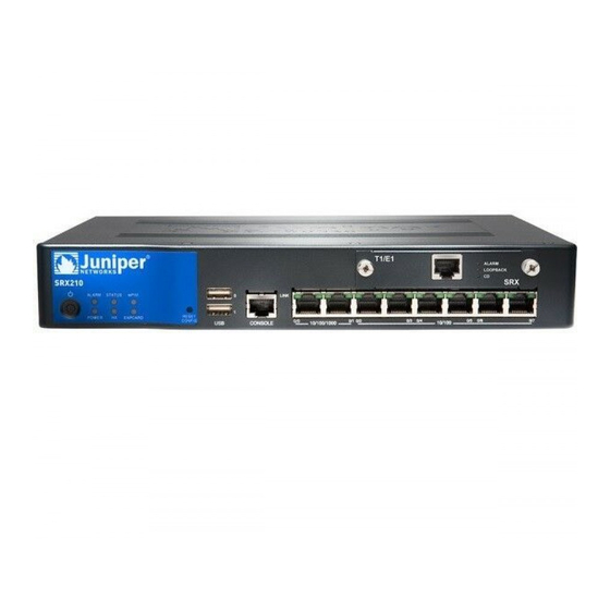
Chapter 2 SRX210 Services Gateway Hardware Components and Specifications This chapter includes the following topics: SRX210 Services Gateway Specifications on page 7 SRX210 Services Gateway Front Panel and Back Panel Views (Low Memory, High Memory and PoE Version) on page 10 SRX210 Services Gateway with Integrated Convergence Services Front Panel and Back Panel Views on page 12 SRX210 Services Gateway Built-In Interfaces on page 14... - Page 28 SRX210 Services Gateway Hardware Guide Figure 1: SRX210 Services Gateway with Integrated Convergence Services Figure 2 on page 8 shows the SRX210 Services Gateway chassis (for low memory, high memory, and PoE models). Figure 2: SRX210 Services Gateway Table 5 on page 8 provides information on the physical specifications of the device. Table 5: SRX210 Services Gateway Specifications Specification Value...
-
Page 29: Srx210 Services Gateway Specifications
Chapter 2: SRX210 Services Gateway Hardware Components and Specifications Table 5: SRX210 Services Gateway Specifications (continued) Specification Value Chassis weight 3.43 lb (1.56 kg) for SRX210 Services Gateway Low Memory and High Memory models 3.50 lb (1.59 kg) for SRX210 Services Gateway with PoE 3.76 lb. -
Page 30: Srx210 Services Gateway Front Panel And Back Panel Views
SRX210 Services Gateway Hardware Guide CAUTION: Before removing or installing components of a functioning services gateway, attach an electrostatic discharge (ESD) strap to an ESD point and place the other end of the strap around your bare wrist. Failure to use an ESD strap could result in damage to the services gateway. -
Page 31: Srx210 Services Gateway Back Panel
Chapter 2: SRX210 Services Gateway Hardware Components and Specifications Table 6: SRX210 Services Gateway Front Panel Components Number Component Mini-PIM slot Power button LEDs: Status, Alarm, Power, 3G ExpressCard, Mini-PIM, HA Reset Config button Universal Serial Bus (USB) ports Console port Gigabit Ethernet ports and Fast Ethernet ports For more information on the front panel components, see the following topics: SRX210 Services Gateway Built-In Interfaces on page 14... -
Page 32: Srx210 Services Gateway With Integrated Convergence Services Front Panel And Back Panel Views
SRX210 Services Gateway Hardware Guide Table 7: SRX210 Services Gateway Back Panel Components Number Component Power supply point Cable tie holder Grounding point Lock ExpressCard slot NOTE: The cable tie holder provides support to hold the power cord on to the power supply point. -
Page 33: Srx210 Services Gateway With Integrated Convergence Services Back Panel
Chapter 2: SRX210 Services Gateway Hardware Components and Specifications Figure 5: SRX210 Services Gateway with Integrated Convergence Services Front Panel Table 8 on page 13 lists the front panel components of the services gateway. NOTE: The numbers in Table 8 on page 13 correspond to the numbers in Figure 5 on page 13. - Page 34 SRX210 Services Gateway Hardware Guide Figure 6: SRX210 Services Gateway with Integrated Convergence Services Back Panel Table 9 on page 14 lists the back panel components of the SRX210 Services Gateway with Integrated Convergence Services. NOTE: The numbers in Figure 6 on page 14 correspond to the numbers in Table 9 on page 14.
- Page 35 Chapter 2: SRX210 Services Gateway Hardware Components and Specifications Table 10: SRX210 Services Gateway Built-In Hardware Interfaces Interface Type Specifications Description Gigabit Ethernet Consist of two fixed ports The Gigabit Ethernet ports can be used as follows: Are labeled as port ge 0/0/0 and port To function as front-end...
- Page 36 Also, the USB device must have JUNOS installed. To provide the USB interfaces that are used to communicate with many types of Juniper supported USB storage devices. Contact your Juniper Networks customer service representative for more information.
-
Page 37: Related Topics Srx210 Services Gateway Specifications
Physical Interface Modules Hardware Guide. NOTE: We strongly recommend that only transceivers provided by Juniper Networks be used on an SRX210 Services Gateway. We cannot guarantee that the interface module will operate correctly if third-party transceivers are used. Contact Juniper Networks for the correct transceiver part number for your device. -
Page 38: Srx210 Services Gateway Leds
SRX210 Services Gateway Hardware Guide SRX210 Services Gateway LEDs on page 18 SRX210 Services Gateway Boot Devices and Dual-Root Partitioning Scheme on page 23 SRX210 Services Gateway Cooling System on page 24 SRX210 Services Gateway Power Supply on page 26 SRX210 Services Gateway LEDs This topic includes the following sections: Front Panel LEDs on page 18... - Page 39 Chapter 2: SRX210 Services Gateway Hardware Components and Specifications Table 11: SRX210 Services Gateway Front Panel Components LEDs Component Description Usage Alarm LED The Alarm LED has the following indicator The Alarm LED can be colors: used to gather information on major or Red and steadily on indicates a major minor alarms or to alarm.
-
Page 40: Ethernet Port Leds
SRX210 Services Gateway Hardware Guide Table 11: SRX210 Services Gateway Front Panel Components LEDs (continued) Component Description Usage The 3G ExpressCard LED has the following The 3G ExpressCard LED ExpressCardLED indicator colors: provides information on the functioning of the Green and steadily on indicates that the ExpressCard slot. -
Page 41: Voice Interface Port Led
Chapter 2: SRX210 Services Gateway Hardware Components and Specifications NOTE: The numbers in Figure 8 on page 20 correspond to the numbers in Table 12 on page 21. Table 12 on page 21 describes the built-in Ethernet port LEDs. Table 12: SRX210 Services Gateway Built-In Ethernet Port LEDs Number Function Color... - Page 42 SRX210 Services Gateway Hardware Guide Figure 9: SRX210 Services Gateway Voice Interface Port LEDs Table 13 on page 22 describes the Voice Interface port LEDs. Table 13: SRX210 Services Gateway Voice Interface Port LEDs Color State Description Voice Interface Unlit Port is inactive.
-
Page 43: Srx210 Services Gateway Boot Devices And Dual-Root Partitioning Scheme
Chapter 2: SRX210 Services Gateway Hardware Components and Specifications SRX210 Services Gateway Cooling System on page 24 SRX210 Services Gateway Power Supply on page 26 SRX210 Services Gateway Boot Devices and Dual-Root Partitioning Scheme This topic includes the following sections: Boot Devices on page 23 Dual-Root Partitioning Scheme on page 23 Boot Devices... -
Page 44: Srx210 Services Gateway Cooling System
SRX210 Services Gateway Hardware Guide For instructions on upgrading to JUNOS Software Release 10.0, see the SRX Series Release Notes. SRX210 Services Gateway Specifications on page 7 Related Topics SRX210 Services Gateway Front Panel and Back Panel Views (Low Memory, High Memory and PoE Version) on page 10 SRX210 Services Gateway with Integrated Convergence Services Front Panel and Back Panel Views on page 12... -
Page 45: Srx210 Services Gateway Cooling System
Chapter 2: SRX210 Services Gateway Hardware Components and Specifications Figure 10: Airflow Through the Chassis (SRX210 Services Gateway with Low Memory, High Memory, and PoE Models) Air flow Rear Front Figure 11 on page 26 shows the airflow through the chassis for the SRX210 Services Gateway with Integrated Convergence Services model. -
Page 46: Srx210 Services Gateway Power Supply
SRX210 Services Gateway Power Supply The power supply for the SRX210 Services Gateway is external. You must use the power supply adapter provided by Juniper Networks to provide power to the services gateway. Figure 12 on page 27 shows the label for the 48 V power supply. - Page 47 48 V Power Supply Figure 13 on page 27 shows the label for the 54 V power supply. Figure 13: SRX210 Services Gateway 54 V Power Supply 150W AD/DC ADAPTER JUNIPER P/N:740-027642 MODEL : EADP-150NB B REV: S3 INPUT : 100-240V ~ 2.5A(2,5A) 50-60Hz...
- Page 48 SRX210 Services Gateway Hardware Guide SRX210 Services Gateway with Integrated Convergence Services Front Panel and Back Panel Views on page 12 SRX210 Services Gateway Boot Devices and Dual-Root Partitioning Scheme on page 23 SRX210 Services Gateway Cooling System on page 24 Monitoring the SRX210 Services Gateway Power System on page 125 SRX210 Services Gateway Power Supply...
-
Page 49: Srx210 Services Gateway 3G Expresscard
Chapter 3 SRX210 Services Gateway 3G ExpressCard This chapter includes the following topics: SRX210 Services Gateway 3G ExpressCard Overview on page 29 Installing the 3G ExpressCard in the SRX210 Services Gateway ExpressCard Slot on page 32 SRX210 Services Gateway 3G ExpressCard Basic CLI Commands on page 33 SRX210 Services Gateway 3G ExpressCard Overview This topic provides an overview of the SRX210 Services Gateway 3G ExpressCard and it includes the following sections:... -
Page 50: Key Features
SRX210 Services Gateway Hardware Guide Table 14: Juniper Networks Wireless Modems Supported by the SRX210 Services Gateway Wireless Cards Release Supported EXPCD-3G-CDMA-V: 3G EVDO ExpressCard for Verizon Wireless. Currently JUNOS Software Releases 9.6, 10.0, 10.1, and available from Juniper Networks. -
Page 51: Physical Specifications
Chapter 3: SRX210 Services Gateway 3G ExpressCard NOTE: Only GSM cards support locking and unlocking of the SIM. Interface support — The ExpressCard interface supports the IP over PPP interface from the network through the wireless link. Dial-out support — The dialer interface can place calls and has multiple features such as dial-backup, dialer-watchlist, and dialer-filter. -
Page 52: Installing The 3G Expresscard In The Srx210 Services Gateway Expresscard Slot
Installing the 3G ExpressCard in the SRX210 Services Gateway ExpressCard Slot TIP: Placing the SRX210 Services Gateway on a flat, level surface, with the Juniper Networks logo facing up, will make it easier to align and insert the 3G ExpressCard in the ExpressCard slot. - Page 53 Chapter 3: SRX210 Services Gateway 3G ExpressCard Figure 14: Installing 3G ExpressCard in the SRX210 Services Gateway Insert the 3G ExpressCard slowly and firmly into the ExpressCard slot until the 3G ExpressCard is engaged in the slot as follows: The 3G ExpressCard is designed to fit tightly in the slot. You will encounter two points of resistance while inserting the 3G ExpressCard into the slot.
- Page 54 SRX210 Services Gateway Hardware Guide Table 16: SRX210 Services Gateway 3G ExpressCard Basic CLI Commands (continued) Action Command Activates the CDMA ExpressCard request modem wireless activate IOTA — Activates Internet-based over request modem wireless activate iota cl-0/0/8 air provisioning . request modem wireless activate manual Manual activation —...
-
Page 55: Srx210 Services Gateway Power Over Ethernet Support
Chapter 4 SRX210 Services Gateway Power over Ethernet Support This chapter includes the following topics: SRX210 Services Gateway PoE Overview on page 35 Configuring PoE Functionality on the SRX210 Services Gateway on page 37 SRX210 Services Gateway PoE Overview This topic includes the following sections: Introduction on page 35 PoE Classes and Power Ratings on page 36 Introduction... -
Page 56: Poe Classes And Power Ratings
The PoE+ functionality is available from JUNOS Software Release 10.2 or later. The PoE+ functionality is available only if your gateway is using 54V power supply. You can order the 54V power supply from Juniper Networks. Contact your Juniper Networks customer service representative for more information. -
Page 57: Configuring Poe Functionality On The Srx210 Services Gateway
Chapter 4: SRX210 Services Gateway Power over Ethernet Support Table 18: PoE Classes and Power Ratings on the SRX210 Services Gateway Class Maximum Power Level Output from the PoE Port 15.4 watts 4.0 watts 7.0 watts 15.4 watts 30.0 watts SRX210 Services Gateway Description on page 3 Related Topics SRX210 Services Gateway Specifications on page 7... - Page 58 SRX210 Services Gateway Hardware Guide Configuring PoE Functionality on the SRX210 Services Gateway...
-
Page 59: Srx210 Services Gateway With Integrated Convergence Services
Chapter 5 SRX210 Services Gateway with Integrated Convergence Services This chapter includes the following topics: About the SRX210 Services Gateway with Integrated Convergence Services on page 39 Understanding the Functions of the SRX210 Services Gateway with Integrated Convergence Services on page 41 SRX210 Services Gateway Integrated Convergence Services Interoperability on page 42 Configuring the SRX210 Services Gateway with Integrated Convergence... -
Page 60: Basic Functions
SRX210 Services Gateway Hardware Guide Basic Functions The availability of hardware and software for voice and data transmission on the same device is called integrated convergence services. SRX210 Services Gateway with Integrated Convergence Services implements a media gateway and a survivable call server. The SRX210 Services Gateway with Integrated Convergence Services integrates voice and data capabilities and provides a generic SIP-based voice over IP (VoIP) Media Gateway (SVMG) capability for local public switched telephone network (PSTN) and legacy analog/fax/phone connectivity. -
Page 61: Common Deployment Scenarios
Chapter 5: SRX210 Services Gateway with Integrated Convergence Services Common Deployment Scenarios The SRX210 Services Gateway with Integrated Convergence Services is deployed in following environments: Enterprises that deploy VoIP in their headquarters and want to enable VoIP functionality for their branch offices. Services providers (SPs) who provide VoIP services to their business customers. - Page 62 SRX210 Services Gateway Hardware Guide NOTE: The 2-Port FXS/2-Port FXO Mini-PIM and the 4-Port FXO Mini-PIM does not support failover relay between any of the FXS and FXO ports. Telephony interface expansion available through Mini-PIM interface card option includes a 2–Port FXS/2–Port FXO Mini-PIM, 4–Port FXO Mini-PIM, and an IP Flex T1/E1 Mini-PIM with initial support for T1-CAS (loopstart only).
- Page 63 Chapter 5: SRX210 Services Gateway with Integrated Convergence Services Table 19: SRX210 Services Gateway Integrated Convergence Services Interoperability (continued) Phone Types Devices Analog devices Any analog device including the phones, FAX machines, PBX or key systems, voice mail or answering machine, and analog paging systems. SIP call servers Avaya CM 5.2 with SES Avaya ASM (Aura 1.x)
- Page 64 SRX210 Services Gateway Hardware Guide Configuring the SRX210 Services Gateway with Integrated Convergence Services...
-
Page 65: Srx210 Services Gateway Mini-Physical Interface Modules
Chapter 6 SRX210 Services Gateway Mini-Physical Interface Modules This chapter includes the following topic: SRX210 Services Gateway Mini-Physical Interface Modules on page 45 SRX210 Services Gateway Mini-Physical Interface Modules The SRX210 Services Gateway supports Mini-Physical Interface Modules (Mini-PIMs). A Mini-PIM is a network interface card (NIC) that is installed on the services gateway to provide physical connections to a LAN or a WAN. - Page 66 SRX210 Services Gateway Hardware Guide SRX210 Services Gateway Mini-Physical Interface Modules...
- Page 67 Part 2 Setting Up the SRX210 Services Gateway Preparing the Site for the SRX210 Services Gateway Installation on page 49 Installation Overview for the SRX210 Services Gateway on page 57 Required Tools and Parts for Installing and Maintaining the SRX210 Services Gateway on page 59 Unpacking the SRX210 Services Gateway on page 61 Preparing the SRX210 Services Gateway for Installation on page 65...
- Page 68 SRX210 Services Gateway Hardware Guide Setting Up the SRX210 Services Gateway...
-
Page 69: Site Preparation Checklist For The Srx210 Services Gateway
Chapter 7 Preparing the Site for the SRX210 Services Gateway Installation This chapter provides a checklist to help you prepare your site for installation of the SRX210 Services Gateway. Read this section to make sure that your site has the proper operating environment and equipment. - Page 70 SRX210 Services Gateway Hardware Guide Table 20: Site Preparation Checklist for the SRX210 Services Gateway Installation (continued) Date Item or Task Additional Information Notes Measure distance between external power “SRX210 Services Gateway Site sources and device installation site. Electrical Wiring Guidelines” on page 157 Locate sites for connection of system grounding.
- Page 71 Chapter 7: Preparing the Site for the SRX210 Services Gateway Installation Installation Overview for the SRX210 Services Gateway on page 57 SRX210 Services Gateway Cabinet Requirements on page 51 SRX210 Services Gateway Rack Requirements on page 52 Clearance Requirements for Airflow and Hardware Maintenance of the SRX210 Services Gateway on page 54 General Site Guidelines for Installing the SRX210 Services Gateway The following precautions help you plan an acceptable operating environment for...
- Page 72 SRX210 Services Gateway Hardware Guide Table 21: SRX210 Services Gateway Cabinet Requirements Cabinet Requirements Specifications Cabinet size 19 in. (48.3 cm) as defined in Cabinets, Racks, Panels, and Associated Equipment (document number EIA-310–D) published by the Electronics Industry Association (http://www.eia.org). You can mount the services gateway horizontally in the cabinet.
- Page 73 Chapter 7: Preparing the Site for the SRX210 Services Gateway Installation NOTE: The services gateway cannot be center-mounted in racks. Table 22 on page 53 provides the details on rack size, clearance, and airflow requirements. Table 22: Rack Requirements for the Services Gateway Rack Requirements Specifications Rack Size...
-
Page 74: Clearance Requirements For Airflow And Hardware Maintenance Of The Srx210 Services Gateway
SRX210 Services Gateway Hardware Guide Clearance Requirements for Airflow and Hardware Maintenance of the SRX210 Services Gateway When planning the installation site for the SRX210 Services Gateway, you need to allow sufficient clearance around the rack or cabinet where you are planning to install the device. -
Page 75: Srx210 Services Gateway Electrical And Power Requirements
Chapter 7: Preparing the Site for the SRX210 Services Gateway Installation SRX210 Services Gateway Description on page 3 Related Topics General Site Guidelines for Installing the SRX210 Services Gateway on page 51 Site Preparation Checklist for the SRX210 Services Gateway on page 49 SRX210 Services Gateway Cabinet Requirements on page 51 SRX210 Services Gateway Rack Requirements on page 52 SRX210 Services Gateway Electrical and Power Requirements... - Page 76 SRX210 Services Gateway Hardware Guide SRX210 Services Gateway Electrical and Power Requirements...
-
Page 77: Chapter 8 Installation Overview For The Srx210 Services Gateway
Chapter 8 Installation Overview for the SRX210 Services Gateway This chapter includes the following topic: Installation Overview for the SRX210 Services Gateway on page 57 Installation Overview for the SRX210 Services Gateway After you have prepared your installation site, you are ready to unpack and install the services gateway. -
Page 78: Installation Overview For The Srx210 Services Gateway
SRX210 Services Gateway Hardware Guide Table 24: Installation Process Order for the SRX210 Services Gateway (continued) Step Task For more information, see Connect the grounding cables. “Grounding the SRX210 Services Gateway” on page 84 Power on the services gateway. “Powering On and Powering Off the SRX210 Services Gateway”... -
Page 79: Required Tools And Parts For Installing And Maintaining The Srx210 Services Gateway
Chapter 9 Required Tools and Parts for Installing and Maintaining the SRX210 Services Gateway This chapter includes the following topic: Required Tools and Parts for Installing and Maintaining the SRX210 Services Gateway on page 59 Required Tools and Parts for Installing and Maintaining the SRX210 Services Gateway Table 25 on page 59 lists the tools and equipments required to install and maintain the SRX210 Services Gateway. - Page 80 SRX210 Services Gateway Hardware Guide Table 25: Required Tools and Parts for Installing and Maintaining the SRX210 Services Gateway (continued) Task Tools and Parts Related Topic Packing the SRX210 Services Blank panel to cover “Packing the SRX210 Services Gateway empty Mini-PIM slot Gateway and Components for Shipment”...
-
Page 81: Chapter 10 Unpacking The Srx210 Services Gateway
Chapter 10 Unpacking the SRX210 Services Gateway This chapter includes the following topics: Unpacking the SRX210 Services Gateway on page 61 Verifying Parts Received with the SRX210 Services Gateway on page 61 Unpacking the SRX210 Services Gateway The SRX210 Services Gateway is shipped in a cardboard carton. The carton also contains an accessory box and the SRX210 Services Gateway Getting Started Guide. - Page 82 The packing list specifies the part numbers and descriptions of each part in your order. If any part is missing, contact your Juniper Networks customer service representative. A fully configured SRX210 Services Gateway contains the chassis with installed components, listed in Table 26 on page 62, and an accessory box, which contains the parts listed in Table 27 on page 62.
- Page 83 NOTE: The Mini-Physical Interface Modules (Mini-PIMs) are not shipped with the device. You have to order them separately. Contact your Juniper Networks customer service representative for more information. Required Tools and Parts for Installing and Maintaining the SRX210 Services...
- Page 84 SRX210 Services Gateway Hardware Guide Verifying Parts Received with the SRX210 Services Gateway...
-
Page 85: Chapter 11 Preparing The Srx210 Services Gateway For Installation
Preparing the SRX210 Services Gateway for Wall-Mount Installation on page 68 The mounting kits for rack, wall, and desk installation of the SRX210 Services Gateway must be ordered separately. Contact your Juniper Networks customer service representative for more information. Site Preparation Checklist for the SRX210 Services Gateway on page 49... -
Page 86: Preparing The Srx210 Services Gateway For Rack-Mount Installation
SRX210 Services Gateway Hardware Guide Preparing the SRX210 Services Gateway for Rack-Mount Installation You can mount an SRX210 Services Gateway on four-post (telco) racks, enclosed cabinets, and open-frame racks. NOTE: The SRX210 Services Gateway cannot be center-mounted in racks. Table 28 on page 66 provides the list of tasks you need to perform before installing the device. -
Page 87: Preparing The Srx210 Services Gateway For Desk-Mount Installation
Chapter 11: Preparing the SRX210 Services Gateway for Installation Site Preparation Checklist for the SRX210 Services Gateway on page 49 Related Topics Clearance Requirements for Airflow and Hardware Maintenance of the SRX210 Services Gateway on page 54 Unpacking the SRX210 Services Gateway on page 61 Preparing the SRX210 Services Gateway for Rack-Mount, Desk-Mount, and Wall-Mount Installation on page 65 Preparing the SRX210 Services Gateway for Desk-Mount Installation on page 67... -
Page 88: Preparing The Srx210 Services Gateway For Wall-Mount Installation
SRX210 Services Gateway Hardware Guide Site Preparation Checklist for the SRX210 Services Gateway on page 49 Related Topics Clearance Requirements for Airflow and Hardware Maintenance of the SRX210 Services Gateway on page 54 Unpacking the SRX210 Services Gateway on page 61 Preparing the SRX210 Services Gateway for Rack-Mount Installation on page 66 Preparing the SRX210 Services Gateway for Wall-Mount Installation on page 68 Preparing the SRX210 Services Gateway for Wall-Mount Installation... -
Page 89: Chapter 12 Installing The Srx210 Services Gateway
Preparing the SRX210 Services Gateway for Rack-Mount, Desk-Mount, and Wall-Mount Installation on page 65 General Site Guidelines for Installing the SRX 210 Services Gateway SRX210 Services Gateway Installation You can install the SRX210 Services Gateway in a rack, on a desk, or on a wall. The device includes rubber feet for desk and wall mounting. -
Page 90: Adjusting The Power Supply Adapter Tray For The Srx210 Services Gateway For Rack-Mount Installation
SRX210 Services Gateway Hardware Guide Install the device as appropriate for your site using one of the following procedures: Adjusting the Power Supply Adapter Tray for the SRX210 Services Gateway for Rack-Mount Installation on page 70 Installing the SRX210 Services Gateway in a Rack on page 71 Installing the SRX210 Services Gateway on a Desk on page 75 Installing the SRX210 Services Gateway on a Wall on page 76 Adjusting the Power Supply Adapter Tray for the SRX210 Services Gateway for Rack-Mount... - Page 91 Chapter 12: Installing the SRX210 Services Gateway To accommodate the 150-watt power supply, use the 420–028535 screw to attach the adapter stopper bracket at the point on the chassis marked A. Figure 16 on page 71 shows the adjustments to the power supply adapter tray required for the 150-watt power supply.
- Page 92 SRX210 Services Gateway Hardware Guide NOTE: If you are installing multiple devices in one rack, install the lowest one first and proceed upward in the rack. Ensure that the rubber feet from the base of the chassis are removed for rack installation.
- Page 93 Chapter 12: Installing the SRX210 Services Gateway Figure 18: SRX210 Services Gateway Rack Installation Securing Mounting Brackets and Power Supply Adapter Tray Place the power supply adapter in the tray as shown in Figure 19 on page 73. Figure 19: SRX210 Services Gateway Rack Installation Positioning Power Supply Adapter Tray Have one person grasp the sides of the device, lift it, and position it in the rack.
- Page 94 SRX210 Services Gateway Hardware Guide Figure 20: SRX210 Services Gateway Rack Installation Hanging the Services Gateway in a Rack Have a second person install a mounting screw into each of the two aligned holes. Use a number-3 Phillips screwdriver to tighten the screws. Install the second screw in each mounting bracket.
-
Page 95: Installing The Srx210 Services Gateway On A Desk
Make sure that the rubber feet are attached to the chassis. Place the device on a desk with the Juniper Networks logo embossed on the top cover facing up. To install the device in a vertical position: Place the device on a flat and level surface with the Juniper Networks logo embossed on the top cover facing up. -
Page 96: Installing The Srx210 Services Gateway On A Wall
SRX210 Services Gateway Hardware Guide Figure 22: SRX210 Services Gateway Desk Installation Placing the Services Gateway on Desk SRX210 Services Gateway General Safety Guidelines and Warnings on page 133 Related Topics Required Tools and Parts for Installing and Maintaining the SRX210 Services Gateway on page 59 Preparing the SRX210 Services Gateway for Desk-Mount Installation on page 67 Installing the SRX210 Services Gateway in a Rack on page 71... - Page 97 Chapter 12: Installing the SRX210 Services Gateway Place the device on a flat and level surface with Juniper Networks logo embossed on the top cover facing up. Ensure that rubber feet are attached to the bottom of the chassis. Position a mounting bracket on each side of the chassis as shown in Figure 23 on page 77.
-
Page 98: Replacing Or Installing Mini-Physical Interface Modules In The Srx210 Services Gateway
SRX210 Services Gateway Hardware Guide Figure 24: SRX210 Services Gateway Wall Installation Hanging the Services Gateway on Wall SRX210 Services Gateway General Safety Guidelines and Warnings on page 133 Related Topics Required Tools and Parts for Installing and Maintaining the SRX210 Services Gateway on page 59 Preparing the SRX210 Services Gateway for Rack-Mount Installation on page 66 Adjusting the Power Supply Adapter Tray for the SRX210 Services Gateway for... - Page 99 Chapter 12: Installing the SRX210 Services Gateway The Mini-Physical Interface Module (Mini-PIM) slot is covered with a blank faceplate to maintain proper airflow through the services gateway. Before installing the Mini-PIM, you must remove the faceplate. See the SRX Series Services Gateways for the Branch Physical Interface Modules Hardware Guide for information about installing Mini-PIMs.
- Page 100 SRX210 Services Gateway Hardware Guide Replacing or Installing Mini-Physical Interface Modules in the SRX210 Services Gateway...
-
Page 101: Chapter 13 Connecting, Grounding, And Powering On The Srx210 Services Gateway
Chapter 13 Connecting, Grounding, and Powering On the SRX210 Services Gateway This chapter includes the following topics: Connecting the SRX210 Services Gateway to the Power Supply on page 81 Connecting and Organizing Interface Cables to the SRX210 Services Gateway on page 83 Grounding the SRX210 Services Gateway on page 84 Powering On and Powering Off the SRX210 Services Gateway on page 85 Connecting the SRX210 Services Gateway to the Power Supply... - Page 102 SRX210 Services Gateway Hardware Guide Figure 25: Connecting the SRX210 Services Gateway to the Power Supply NOTE: The device must be connected to earth ground during normal operation. The protective earthing terminal on the rear of the chassis is provided to connect the device to ground.
-
Page 103: Connecting And Organizing Interface Cables To The Srx210 Services Gateway
Chapter 13: Connecting, Grounding, and Powering On the SRX210 Services Gateway Connecting and Organizing Interface Cables to the SRX210 Services Gateway You can connect the interfaces installed in the services gateway to various network media. Each type of interface on the services gateway uses a particular medium to transmit data. -
Page 104: Grounding The Srx210 Services Gateway
SRX210 Services Gateway Hardware Guide Grounding the SRX210 Services Gateway To meet safety and electromagnetic interference (EMI) requirements and to ensure proper operation, you must adequately ground the SRX210 Services Gateway before connecting power. Figure 26 on page 84 illustrates connecting a grounding cable to the services gateway. Figure 26: Grounding the SRX210 Services Gateway You ground the device by connecting a grounding cable to earth ground and then attaching it to the chassis grounding points using one 6-32 UNC screw. -
Page 105: Powering On And Powering Off The Srx210 Services Gateway
Chapter 13: Connecting, Grounding, and Powering On the SRX210 Services Gateway To ground the device: Connect the grounding cable to a proper earth ground. Verify that a licensed electrician has attached the cable lug to the grounding cable. Place the grounding cable lug over the grounding point on the upper rear of the chassis. - Page 106 SRX210 Services Gateway Hardware Guide NOTE: After the power supply is turned on, it can take up to 60 seconds for status indicators—such as the Status and Power LEDs—to show that the power supply is functioning normally. NOTE: It is recommended to issue the CLI command when request system power-off you want to power off the device immediately after the device is powered on.
- Page 107 Chapter 13: Connecting, Grounding, and Powering On the SRX210 Services Gateway NOTE: To remove power completely from the device, unplug the AC power cord or switch off the power source. After powering off a power supply, wait at least 10 seconds before turning it back on.
- Page 108 SRX210 Services Gateway Hardware Guide Resetting the SRX210 Services Gateway...
-
Page 109: Srx210 Services Gateway Autoinstallation
Chapter 14 SRX210 Services Gateway Autoinstallation This chapter includes the following topic: SRX210 Services Gateway Autoinstallation Overview on page 89 SRX210 Services Gateway Autoinstallation Overview The autoinstallation process begins any time a services gateway is powered on and cannot locate a valid configuration file in the internal flash. Typically, a configuration file is unavailable when a services gateway is powered on for the first time or if the configuration file is deleted from the internal flash. - Page 110 SRX210 Services Gateway Hardware Guide SRX210 Services Gateway Autoinstallation Overview...
-
Page 111: Connecting The Srx210 Services Gateway To Management Devices
Chapter 15 Connecting the SRX210 Services Gateway to Management Devices This chapter includes the following topics: Connecting an SRX210 Services Gateway to the J-Web Interface on page 91 Connecting an SRX210 Services Gateway to the CLI Locally on page 95 Connecting an SRX210 Services Gateway to the CLI Remotely on page 96 Connecting the Modem at the SRX210 Services Gateway End on page 97 Connecting the Modem to the Console Port on the SRX210 Services... - Page 112 SRX210 Services Gateway Hardware Guide Figure 27: Connecting to the Ethernet Port on an SRX210 Services Gateway Connecting an SRX210 Services Gateway to the J-Web Interface...
-
Page 113: Connecting An Srx210 Services Gateway To The J-Web Interface
Chapter 15: Connecting the SRX210 Services Gateway to Management Devices Connecting an SRX210 Services Gateway to the J-Web Interface... - Page 114 SRX210 Services Gateway Hardware Guide To connect to the Ethernet port: From the management device you use to access the J-Web interface (such as a PC or a laptop), verify that the address of the port you connect to is set to one of the following values: Ethernet address on the subnetwork other than...
-
Page 115: Connecting An Srx210 Services Gateway To The Cli Locally
Chapter 15: Connecting the SRX210 Services Gateway to Management Devices Connecting an SRX210 Services Gateway to the CLI Locally If you plan to use the CLI to configure the SRX210 Services Gateway, you must connect through the console port, as shown in Figure 28 on page 95. Figure 28: Connecting to the Console Port on an SRX210 Services Gateway NOTE: Figure 28 on page 95 shows a connection to a local management device. -
Page 116: Connecting An Srx210 Services Gateway To The Cli Remotely
SRX210 Services Gateway Hardware Guide Start your asynchronous terminal emulation application (such as Microsoft Windows HyperTerminal) and select the appropriate port to use (for example, COM1 Configure the port settings shown in Table 34 on page 96. Table 34: Port Settings when Connecting to Console Port Port Settings Value Bits per second... -
Page 117: Connecting The Modem At The Srx210 Services Gateway End
Chapter 15: Connecting the SRX210 Services Gateway to Management Devices Connecting an SRX210 Services Gateway to the CLI Locally on page 95 Related Topics Performing Initial Software Configuration on the SRX210 Services Gateway Using the CLI on page 104 Connecting an SRX210 Services Gateway to the J-Web Interface on page 91 SRX210 Services Gateway Software Configuration Overview on page 101 SRX210 Services Gateway Secure Web Access Overview on page 111 Connecting the Modem at the SRX210 Services Gateway End... -
Page 118: Connecting The Modem To The Console Port On The Srx210 Services Gateway
SRX210 Services Gateway Hardware Guide Configure the modem to accept modem control DTR signals by entering AT&D1 Disable flow control by entering AT&K0 Save modem settings by entering AT&W Connecting the Modem to the Console Port on the SRX210 Services Gateway on Related Topics page 98 Connecting to the CLI at the User End for the SRX210 Services Gateway on... -
Page 119: Connecting To The Cli At The User End For The Srx210 Services Gateway
Chapter 15: Connecting the SRX210 Services Gateway to Management Devices Connecting to the CLI at the User End for the SRX210 Services Gateway To remotely connect to the CLI through a dial-up modem connected to the console port on the services gateway: Connect a modem at your remote location to a management device such as a PC or laptop computer. - Page 120 SRX210 Services Gateway Hardware Guide Connecting to the CLI at the User End for the SRX210 Services Gateway...
-
Page 121: Performing Initial Software Configuration On The Srx210 Services Gateway
Chapter 16 Performing Initial Software Configuration on the SRX210 Services Gateway This chapter includes the following topics: SRX210 Services Gateway Software Configuration Overview on page 101 Performing Initial Software Configuration on the SRX210 Services Gateway Using the CLI on page 104 Performing Initial Software Configuration on the SRX210 Services Gateway Using the J-Web Interface on page 107 SRX210 Services Gateway Secure Web Access Overview on page 111... - Page 122 SRX210 Services Gateway Hardware Guide NOTE: The SRX210 services gateway that ship with JUNOS Release 10.0 or later are formatted with dual-root partitions from the factory. SRX Series devices that are running JUNOS Software Release 9.6 or earlier can be formatted with dual-root partitions when they are upgraded to JUNOS Release 10.0 or later.
- Page 123 Chapter 16: Performing Initial Software Configuration on the SRX210 Services Gateway Table 38 on page 103 shows the mapping of the chassis cluster ports. Table 38: Mapping the Chassis Cluster Ports on an SRX210 Services Gateway Ethernet Ports on SRX210 Services Gateway Management Interface fe-0/0/6 fxp0 (management port)
- Page 124 SRX210 Services Gateway Hardware Guide NOTE: Information sent in cleartext is not encrypted and therefore can be intercepted. If the device is operating in a Common Criteria environment, see the Secure Configuration Guide for Common Criteria and JUNOS-FIPS. Connecting an SRX210 Services Gateway to the J-Web Interface on page 91 Related Topics Connecting an SRX210 Services Gateway to the CLI Locally on page 95 Connecting an SRX210 Services Gateway to the CLI Remotely on page 96...
-
Page 125: Performing Initial Software Configuration On The Srx210 Services Gateway Using The Cli
Chapter 16: Performing Initial Software Configuration on the SRX210 Services Gateway Configure an administrator account on the device. [edit] root@# set system login user admin class super-user authentication plain-text-password Commit the configuration to activate it on the device. [edit] root@# commit Log in as the administrative user you configured in Step 6. - Page 126 SRX210 Services Gateway Hardware Guide Check the configuration for validity. [edit] admin@# commit check configuration check succeeds Commit the configuration to activate it on the device. [edit] admin@# commit commit complete Optionally, display the configuration to verify that it is correct. [edit] user@host# show system {...
-
Page 127: Performing Initial Software Configuration On The Srx210 Services Gateway Using The J-Web Interface
Chapter 16: Performing Initial Software Configuration on the SRX210 Services Gateway Optionally, configure additional properties by adding the necessary configuration statements. Then commit the changes to activate them on the device. [edit] admin@host# commit When you have finished configuring the device, exit configuration mode. [edit] admin@host# exit admin@host>... - Page 128 SRX210 Services Gateway Hardware Guide NOTE: If an IP address is not assigned to the management device, manually configure an IP address in the 192.168.1.0/24 subnetwork. Do not assign the 192.168.1.1 IP address to the management device, as this IP address is assigned to the device. Access the J-Web interface: Launch a Web browser from the management device.
- Page 129 Chapter 16: Performing Initial Software Configuration on the SRX210 Services Gateway Table 39: Basic Configuration Summary (Device Identification) (continued) Field Function Your Action Root Password Sets the password that user Type a plaintext password that the root (required) system encrypts. can use to log in to the services gateway.
- Page 130 SRX210 Services Gateway Hardware Guide Table 41: Basic Configuration Summary (Date and Time) Field Function Your Action Date and Time Time Zone Identifies the time zone in From the list, select the appropriate time zone. which the services gateway is located.
-
Page 131: Srx210 Services Gateway Secure Web Access Overview
Chapter 16: Performing Initial Software Configuration on the SRX210 Services Gateway In the IPv4 Address and Prefix fields, enter an IP address and a subnet mask Click OK. The configured IP address is included in the Address Prefix column. Configure the default route as follows In the J-Web interface, select Configure>Routing>Static routing In the Static Routing page, click Add. - Page 132 SRX210 Services Gateway Hardware Guide transmitted between the Web browser and the services gateway by means of HTTP is vulnerable to interception and attack. To enable secure Web access, the services gateway supports HTTP over Secure Sockets Layer (HTTPS). You can enable HTTP or HTTPS access on specific interfaces and ports as needed.
- Page 133 Part 3 Maintaining and Monitoring the SRX210 Services Gateway Hardware Maintaining the SRX210 Services Gateway Hardware Components on page 115 Monitoring the SRX210 Services Gateway on page 117 Maintaining and Monitoring the SRX210 Services Gateway Hardware...
- Page 134 SRX210 Services Gateway Hardware Guide Maintaining and Monitoring the SRX210 Services Gateway Hardware...
-
Page 135: Maintaining The Srx210 Services Gateway Hardware
Chapter 17 Maintaining the SRX210 Services Gateway Hardware Components This chapter describes how to maintain the hardware components of the SRX210 Services Gateway. This chapter includes the following topic: Maintaining the SRX210 Services Gateway Hardware Components on page 115 Maintaining the SRX210 Services Gateway Hardware Components Table 42 on page 115 describes the common tasks to maintain the hardware components of the services gateway. - Page 136 SRX210 Services Gateway Hardware Guide Connecting the SRX210 Services Gateway to the Power Supply on page 81 Related Topics Clearance Requirements for Airflow and Hardware Maintenance of the SRX210 Services Gateway on page 54 Site Preparation Checklist for the SRX210 Services Gateway on page 49 Maintaining the SRX210 Services Gateway Hardware Components...
-
Page 137: Monitoring The Srx210 Services Gateway
This chapter describes how to monitor the SRX210 Services Gateway hardware components. If you encounter software problems, or problems with hardware components not discussed here, contact the Juniper Networks Technical Assistance Center (JTAC). This chapter includes the following topics: Monitoring Hardware Components on the SRX210 Services Gateway on page 117... - Page 138 SRX210 Services Gateway Hardware Guide The following examples provide the sample output of commands: show chassis hardware For the SRX210 Services Gateway show chassis hardware user@host > Item Version Part number Serial number Description Chassis SRX210b Routing Engine REV X0 750-021778 000000PS2627 RE-SRX210-LOWMEM...
-
Page 139: Monitoring The Srx210 Services Gateway Chassis Using The Cli
Monitoring the SRX210 Services Gateway Using Chassis Alarm Conditions on page 122 Monitoring the SRX210 Services Gateway Power System on page 125 Maintaining the SRX210 Services Gateway Hardware Components on page 115 Juniper Networks Technical Assistance Center on page 128 Monitoring the SRX210 Services Gateway Chassis Using the CLI... -
Page 140: Monitoring The Srx210 Services Gateway Components Using Leds
The device is starting Normal condition. No action is required. The Reset Config button is pressed. An error is detected in the Contact the Juniper device. Networks Technical Assistance Center (JTAC). See “Juniper Networks Technical Assistance Center” on page 128. - Page 141 Chapter 18: Monitoring the SRX210 Services Gateway Table 43: Component LEDs on the Services Gateway (continued) Possible Causes and State Meaning Corrective Actions Power LED Green The device is receiving Normal condition. No power and is functioning action is required. normally.
-
Page 142: Monitoring The Srx210 Services Gateway Using Chassis Alarm Conditions
Changing the Reset Config Button Behavior on the SRX210 Services Gateway on page 127 Juniper Networks Technical Assistance Center on page 128 Monitoring the SRX210 Services Gateway Using Chassis Alarm Conditions When the services gateway detects an alarm condition, the alarm LED on the front panel turns red or amber as appropriate. - Page 143 Juniper Networks Technical Assistance Center (JTAC). See “Juniper Networks Technical Assistance Center” on page 128. Mini-Physical A Mini-PIM has Contact the Juniper Networks Technical Interface failed. Assistance Center (JTAC). See “Juniper (major) Module Networks Technical Assistance Center”...
- Page 144 Using the Reset Config Button on the SRX210 Services Gateway on page 126 Changing the Reset Config Button Behavior on the SRX210 Services Gateway on page 127 Juniper Networks Technical Assistance Center on page 128 Monitoring the SRX210 Services Gateway Using Chassis Alarm Conditions...
- Page 145 Ensure the device has an AC input voltage between 110 and 240 VAC. If you cannot determine the cause of the problem or need additional assistance, contact the Juniper Networks Technical Assistance Center (JTAC). See “Juniper Networks Technical Assistance Center” on page 128.
-
Page 146: Resetting The Configuration File When The Srx210 Services Gateway Is Inaccessible
Changing the Reset Config Button Behavior on the SRX210 Services Gateway on page 127 Juniper Networks Technical Assistance Center on page 128 Resetting the Configuration File When the SRX210 Services Gateway Is Inaccessible You can use the SRX210 Services Gateway's Reset Config button to restore the device's configuration file when the current one is faulty or fails. - Page 147 122 Monitoring the SRX210 Services Gateway Power System on page 125 Juniper Networks Technical Assistance Center on page 128 Changing the Reset Config Button Behavior on the SRX210 Services Gateway You can change the default operation of the Reset Config button by limiting how the...
- Page 148 SRX210 Services Gateway Hardware Guide Monitoring the SRX210 Services Gateway Power System on page 125 Juniper Networks Technical Assistance Center on page 128 Juniper Networks Technical Assistance Center If you need assistance while troubleshooting a services gateway, open a support case...
-
Page 149: Appendixes
Part 4 Appendixes Safety and Regulatory Compliance Information on page 131 SRX210 Services Gateway Power Guidelines, Requirements, and Specifications on page 157 SRX210 Services Gateway Interface Cable Specifications and Connector Pinouts on page 161 Contacting Customer Support and Returning the SRX210 Services Gateway Hardware on page 167 Appendixes... - Page 150 SRX210 Services Gateway Hardware Guide Appendixes...
-
Page 151: Safety And Regulatory Compliance Information
SRX210 Services Gateway Compliance Statements for Acoustic Noise on page 154 SRX210 Services Gateway Definition of Safety Warning Levels This topic defines the following three levels of safety warnings used in Juniper Networks technical publications: NOTE: You might find this information helpful in a particular situation or might otherwise overlook it. - Page 152 SRX210 Services Gateway Hardware Guide WARNING: This symbol means danger. You are in a situation that could cause bodily injury. Before you work on any equipment, be aware of the hazards involved with electrical circuitry and be familiar with standard practices for preventing accidents. Waarschuwing Dit waarschuwingssymbool betekent gevaar.
- Page 153 Appendix A: Safety and Regulatory Compliance Information SRX210 Services Gateway General Safety Guidelines and Warnings on page 133 Related Topics SRX210 Services Gateway Fire Safety Requirements on page 137 SRX210 Services Gateway Installation Safety Guidelines and Warnings on page 138 SRX210 Services Gateway Laser and LED Safety Guidelines and Warnings on page 142 SRX210 Services Gateway Electrical Safety Guidelines and Warnings on page 150...
- Page 154 SRX210 Services Gateway Hardware Guide WARNING: Only trained and qualified personnel should install or replace the services gateway. Waarschuwing Installatie en reparaties mogen uitsluitend door getraind en bevoegd personeel uitgevoerd worden. Varoitus Ainoastaan koulutettu ja pätevä henkilökunta saa asentaa tai vaihtaa tämän laitteen.
- Page 155 Appendix A: Safety and Regulatory Compliance Information Attention Cet appareil est à installer dans des zones d'accès réservé. Ces dernières sont des zones auxquelles seul le personnel de service peut accéder en utilisant un outil spécial, un mécanisme de verrouillage et une clé, ou tout autre moyen de sécurité.
- Page 156 SRX210 Services Gateway Hardware Guide Many services gateway hardware components are sensitive to damage from static electricity. Some components can be impaired by voltages as low as 30 V. You can easily generate potentially damaging static voltages whenever you handle plastic or foam packing material or if you move components across plastic or carpets.
-
Page 157: Srx210 Services Gateway Fire Safety Requirements
NOTE: To keep warranties effective, do not use a dry chemical fire extinguisher to control a fire at or near a Juniper Networks services gateway. If a dry chemical fire extinguisher is used, the unit is no longer eligible for coverage under a service agreement. -
Page 158: Srx210 Services Gateway Installation Safety Guidelines And Warnings
SRX210 Services Gateway Hardware Guide SRX210 Services Gateway Installation Safety Guidelines and Warnings Installation Instructions Warning WARNING: Read the installation instructions before you connect the services gateway to a power source. Waarschuwing Raadpleeg de installatie-aanwijzingen voordat u het systeem met de voeding verbindt. - Page 159 Les directives ci-dessous sont destinées à assurer la protection du personnel: Le rack sur lequel est monté le Juniper Networks services gateway doit être fixé à la structure du bâtiment. Si cette unité constitue la seule unité montée en casier, elle doit être placée dans le bas.
- Page 160 Le seguenti direttive vengono fornite per garantire la sicurezza personale: Il Juniper Networks services gateway deve essere installato in un telaio, il quale deve essere fissato alla struttura dell'edificio. Questa unità deve venire montata sul fondo del supporto, se si tratta dell'unica unità...
-
Page 161: Srx210 Services Gateway Laser And Led Safety Guidelines And Warnings
Para garantizar su seguridad, proceda según las siguientes instrucciones: El Juniper Networks services gateway debe instalarse en un bastidor fijado a la estructura del edificio. Colocar el equipo en la parte inferior del bastidor, cuando sea la única unidad en el mismo. -
Page 162: Laser And Led Safety Guidelines And Warnings
SRX210 Services Gateway Hardware Guide SRX210 Services Gateway Laser and LED Safety Guidelines and Warnings The 1-Port SFP Mini-Physical Interface Module (Mini-PIM) is equipped with laser transmitters, which are considered a Class 1 Laser Product by the U.S. Food and Drug Administration, and they are evaluated as a Class 1 Laser Product per EN 60825–1 +A11 +A2 requirements. -
Page 163: Class 1 Led Product Warning
Appendix A: Safety and Regulatory Compliance Information Varning! Laserprodukt av klass 1. Class 1 LED Product Warning WARNING: Class 1 LED product. Waarschuwing Klasse 1 LED-product. Varoitus Luokan 1 valodiodituote. Attention Alarme de produit LED Class I. Warnung Class 1 LED-Produktwarnung. Avvertenza Avvertenza prodotto LED di Classe 1. -
Page 164: Radiation From Open Port Apertures Warning
SRX210 Services Gateway Hardware Guide Aviso Não olhe fixamente para o raio, nem olhe para ele directamente com instrumentos ópticos. ¡Atención! No mirar fijamente el haz ni observarlo directamente con instrumentos ópticos. Varning! Rikta inte blicken in mot strålen och titta inte direkt på den genom optiska instrument. -
Page 165: Srx210 Services Gateway Maintenance And Operational Safety Guidelines And Warnings
Appendix A: Safety and Regulatory Compliance Information SRX210 Services Gateway Installation Safety Guidelines and Warnings on page 138 Related Topics SRX210 Services Gateway Maintenance and Operational Safety Guidelines and Warnings on page 145 SRX210 Services Gateway Maintenance and Operational Safety Guidelines and Warnings This topic includes the following section: Safety Guidelines and Warnings on page 145... -
Page 166: Jewelry Removal Warning
SRX210 Services Gateway Hardware Guide ¡Atención! Existe peligro de explosión si la batería se reemplaza de manera incorrecta. Reemplazar la batería exclusivamente con el mismo tipo o el equivalente recomendado por el fabricante. Desechar las baterías gastadas según las instrucciones del fabricante. -
Page 167: Lightning Activity Warning
Appendix A: Safety and Regulatory Compliance Information Aviso Antes de trabalhar em equipamento que esteja ligado a linhas de corrente, retire todas as jóias que estiver a usar (incluindo anéis, fios e relógios). Os objectos metálicos aquecerão em contacto com a corrente e em contacto com a ligação à terra, podendo causar queimaduras graves ou ficarem soldados aos terminais. -
Page 168: Operating Temperature Warning
40 C. Ettei ilmanvaihto estyisi, tuuletusaukkojen ympärille on jätettävä ainakin 15,2 cm tilaa. Attention Pour éviter toute surchauffe des routeurs de la gamme Juniper Networks services gateway, ne l'utilisez pas dans une zone où la température ambiante est supérieure à 40 C. Pour permettre un flot d'air constant, dégagez un espace d'au moins 15,2 cm autour des ouvertures de ventilations. -
Page 169: Product Disposal Warning
Appendix A: Safety and Regulatory Compliance Information Varning! Förhindra att en Juniper Networks services gateway överhettas genom att inte använda den i ett område där den maximalt rekommenderade omgivningstemperaturen på 40 C överskrids. Förhindra att luftcirkulationen inskränks genom att se till att det finns fritt utrymme på minst 15,2 cm omkring ventilationsöppningarna. - Page 170 SRX210 Services Gateway Hardware Guide SRX210 Services Gateway Electrical Safety Guidelines and Warnings In Case of Electrical Accident If an electrical accident results in an injury, take the following actions in this order: Use caution. Be aware of potentially hazardous conditions that could cause further injury.
-
Page 171: Srx210 Services Gateway Agency Approvals
Appendix A: Safety and Regulatory Compliance Information SRX210 Services Gateway Agency Approvals The SRX210 Services Gateway complies with the following standards: Safety CSA 60950-1 (2003) Safety of Information Technology Equipment UL 60950-1 (2003) Safety of Information Technology Equipment EN 60950-1 (2001) Safety of Information Technology Equipment IEC 60950-1 (2001) Safety of Information Technology Equipment (with country deviations) EN 60825-1 +A1+A2 (1994) Safety of Laser Products - Part 1: Equipment... -
Page 172: Srx210 Services Gateway Compliance Statements For Emc Requirements
SRX210 Services Gateway Hardware Guide Immunity EN 55024 +A1+A2 (1998) Information Technology Equipment Immunity Characteristics EN-61000-3-2 (2006) Power Line Harmonics EN-61000-3-3 +A1 +A2 +A3 (1995) Power Line Voltage Fluctuations EN-61000-4-2 +A1 +A2 (1995) Electrostatic Discharge EN-61000-4-3 +A1+A2 (2002) Radiated Immunity EN-61000-4-4 (2004) Electrical Fast Transients EN-61000-4-5 (2006) Surge EN-61000-4-6 (2007) Immunity to Conducted Disturbances... - Page 173 Appendix A: Safety and Regulatory Compliance Information The preceding translates as follows: This is a Class B product based on the standard of the Voluntary Control Council for Interference by Information Technology Equipment (VCCI). If this product is used near a radio or television receiver in a domestic environment, it may cause radio interference.
- Page 174 SRX210 Services Gateway Hardware Guide This is a Class A product based on the standard of the Voluntary Control Council for Interference by Information Technology Equipment (VCCI). If this equipment is used in a domestic environment, radio interference may occur, in which case, the user may be required to take corrective actions.
- Page 175 Appendix A: Safety and Regulatory Compliance Information SRX210 Services Gateway Compliance Statements for EMC Requirements on Related Topics page 152 SRX210 Services Gateway Compliance Statements for Environmental Requirements on page 154 SRX210 Services Gateway Agency Approvals on page 151 SRX210 Services Gateway Compliance Statements for Acoustic Noise...
- Page 176 SRX210 Services Gateway Hardware Guide SRX210 Services Gateway Compliance Statements for Acoustic Noise...
-
Page 177: Srx210 Services Gateway Power Guidelines, Requirements, And Specifications
Appendix B SRX210 Services Gateway Power Guidelines, Requirements, and Specifications This appendix includes the following topics: SRX210 Services Gateway Site Electrical Wiring Guidelines on page 157 SRX210 Services Gateway Power Specifications and Requirements on page 158 SRX210 Services Gateway Grounding Specifications on page 159 SRX210 Services Gateway Site Electrical Wiring Guidelines Table 46 on page 157 describes the factors you must consider while planning the electrical wiring for the services gateway at your site. - Page 178 SRX210 Services Gateway Hardware Guide Table 46: Site Electrical Wiring Guidelines for the Services Gateway (continued) Site Wiring Factor Guideline Radio Frequency To reduce or eliminate the emission of RFI from your site wiring: Interference (RFI) Use twisted-pair cable with a good distribution of grounding conductors.
- Page 179 Appendix B: SRX210 Services Gateway Power Guidelines, Requirements, and Specifications Table 47: Power Supply Electrical Specifications for the SRX210 Services Gateway (continued) Power Requirement Specification AC system current rating 1.5 A maximum 2.5 A maximum (for PoE and Voice models) WARNING: The AC power cord for the services gateway is intended for use with the device only and not for any other use.
- Page 180 SRX210 Services Gateway Hardware Guide Table 48: Grounding Cable Specifications for the Services Gateway (continued) Grounding Requirement Specification Amperage of grounding cable Up to 4 A Grounding lug Ring-type, vinyl-insulated TV14-6R lug or equivalent SRX210 Services Gateway Site Electrical Wiring Guidelines on page 157 Related Topics SRX210 Services Gateway Power Specifications and Requirements on page 158 Grounding the SRX210 Services Gateway on page 84...
-
Page 181: Srx210 Services Gateway Interface Cable Specifications And
Appendix C SRX210 Services Gateway Interface Cable Specifications and Connector Pinouts The network interfaces supported on the services gateway accept different types of network cables. This appendix includes the following topics: Interface Cable and Wire Specifications for the SRX210 Services Gateway on page 161 RJ-45 Connector Pinouts for the SRX210 Services Gateway Ethernet Port on page 162... -
Page 182: Connector Pinouts For The Srx210 Services Gateway Ethernet Port
SRX210 Services Gateway Hardware Guide RJ-45 Connector Pinouts for the SRX210 Services Gateway Ethernet Port on Related Topics page 162 RJ-45 Connector Pinouts for the SRX210 Services Gateway Console Port on page 163 SRX210 Services Gateway Front Panel and Back Panel Views (Low Memory, High Memory and PoE Version) on page 10 RJ-45 Connector Pinouts for the SRX210 Services Gateway Ethernet Port Figure 30 on page 162 shows the RJ-45 cable connector pinouts for Ethernet ports. -
Page 183: Rj-45 Connector Pinouts For The Srx210 Services Gateway Console Port
Appendix C: SRX210 Services Gateway Interface Cable Specifications and Connector Pinouts Table 51: RJ-45 Connector Pinouts for the Services Gateway Ethernet Port (1 Gbps) Signal BI_DA+ BI_DA- BI_DB+ BI_DC+ BI_DC- BI_DB- BI_DD+ BI_DD- Interface Cable and Wire Specifications for the SRX210 Services Gateway on Related Topics page 161 RJ-45 Connector Pinouts for the SRX210 Services Gateway Console Port on... -
Page 184: Rj-11 Connector Pinouts For The Srx210 Services Gateway With Integrated Convergence Services Fxo And Fxs Ports
SRX210 Services Gateway Hardware Guide Table 52: RJ-45 Connector Pinouts for Services Gateway Console Port (continued) Signal Description Ground Signal Ground Receive Data DSR/DCD Data Set Ready Clear to Send Interface Cable and Wire Specifications for the SRX210 Services Gateway on Related Topics page 161 RJ-45 Connector Pinouts for the SRX210 Services Gateway Ethernet Port on... - Page 185 Appendix C: SRX210 Services Gateway Interface Cable Specifications and Connector Pinouts Interface Cable and Wire Specifications for the SRX210 Services Gateway on Related Topics page 161 RJ-45 Connector Pinouts for the SRX210 Services Gateway Ethernet Port on page 162 RJ-45 Connector Pinouts for the SRX210 Services Gateway Console Port on page 163 SRX210 Services Gateway with Integrated Convergence Services Front Panel and Back Panel Views on page 12...
- Page 186 SRX210 Services Gateway Hardware Guide RJ-11 Connector Pinouts for the SRX210 Services Gateway with Integrated Convergence Services FXO and FXS Ports...
-
Page 187: Contacting Customer Support And Returning The Srx210 Services Gateway Hardware
Hardware This appendix describes how to return the SRX210 Services Gateway or an individual component such as Mini-Physical Interface module (Mini-PIM) to Juniper Networks for repair or replacement. This appendix includes the following topics: Return Procedure for the SRX210 Services Gateway on page 167... -
Page 188: Listing The Srx210 Services Gateway And Component Details With The Cli
SRX210 Services Gateway Hardware Guide NOTE: Do not return the device or any component to Juniper Networks unless you have first obtained an RMA number. Juniper Networks reserves the right to refuse shipments that do not have an RMA. Refused shipments are returned to the customer via collect freight. -
Page 189: Srx210 Services Gateway Chassis Serial Number And Agency Labels
Appendix D: Contacting Customer Support and Returning the SRX210 Services Gateway Hardware PIC 0 2x GE, 6x FE, 1x Power Supply 0 NOTE: In the command, the Mini-Physical Interface Module show chassis hardware (Mini-PIM) slot number is reported as an FPC number, and the Mini-PIM number (always 0) is reported as the PIC number. -
Page 190: Contacting Customer Support To Obtain Return Materials Authorization
Contacting Customer Support on page 170 Information You Might Need to Supply to Juniper Networks Technical Assistance Center If you are returning a services gateway or hardware component to Juniper Networks for repair or replacement, obtain a Return Materials Authorization (RMA) number from Juniper Networks Technical Assistance Center (JTAC). -
Page 191: Packing The Srx210 Services Gateway And Components For Shipment
To pack the services gateway for shipment: Retrieve the shipping carton and packing materials in which the device was originally shipped. If you do not have these materials, contact your Juniper Networks representative about approved packaging materials. Attach an electrostatic discharge (ESD) grounding strap to your bare wrist and connect the strap to the ESD point on the chassis or to an outside ESD point if the device is disconnected from earth ground. - Page 192 Gateway on page 59 Locating an SRX210 Services Gateway Component Serial Number and Agency Labels on page 168 Information You Might Need to Supply to Juniper Networks Technical Assistance Center on page 170 Return Procedure for the SRX210 Services Gateway on page 167...
- Page 193 Part 5 Index Index on page 175 Index...
- Page 194 SRX210 Services Gateway Hardware Guide Index...
- Page 195 Index braces, in configuration statements......xvii brackets Symbols angle, in syntax descriptions.......xvii #, comments in configuration statements....xvii square, in configuration statements....xvii ( ), in syntax descriptions...........xvii using..............29 3G ExpressCard............29 cables < >, in syntax descriptions........xvii console port cable (chassis), connecting..95, 98 [ ], in configuration statements........xvii Ethernet cable, connecting......95, 98 { }, in configuration statements.........xvii...
- Page 196 SRX210 Services Gateway Hardware Guide cooling system.............24 guidelines maintenance............115 electrical.............150 curly braces, in configuration statements....xvii electrical wiring..........157 installing...............51 DB-9 to DB-25 serial port adapter........98 DDR Memory..............4 HA LED................19 desk hardware components installing...............75 maintenance............115 desk installation monitoring............122 preparing..............67 Hayes-compatible modem See modem connection to desk mount console port preparing..............67...
- Page 197 JTAC..............128, 170 pinouts...............164 information required...........170 RJ-45............162, 163 requesting support..........170 PoE................3, 35 Juniper Networks Technical Assistance Center...128 configuring............37 Juniper Technical Assistance Center See JTAC PoE Status LED............21 JUNOS CLI Port LED connecting locally..........95 TX/RX, POE............20 connecting remotely..........95 port settings..............97 JUNOS software power establishing secure Web access......111...
- Page 198 SRX210 Services Gateway Hardware Guide return rack installation............71 component............167 return procedure ..........167 services gateway..........167 SSL access............111 RJ-11 connector pinouts..........164 tools..............59 RJ-45 pinouts unpacking.............61 console port............163 verifying parts............61 Ethernet port............162 wall installation.............76 RJ-45 to DB-9 serial port adapter Services Gateway chassis console port..........98 configuration............101 root password show chassis commands...
- Page 199 Index wall mount preparing..............68 warnings electrical.............150 wire specifications.............161 wireless................29 Index...
- Page 200 SRX210 Services Gateway Hardware Guide Index...
Need help?
Do you have a question about the SRX 210 and is the answer not in the manual?
Questions and answers