Juniper SRX220 Hardware Manual
H
h model numbers
Hide thumbs
Also See for SRX220:
- Manual (170 pages) ,
- Quick start manual (6 pages) ,
- Quick start (4 pages)

Subscribe to Our Youtube Channel
Related Manuals for Juniper SRX220


Summary of Contents for Juniper SRX220
- Page 1 SRX220 Services Gateway Hardware Guide for H Model Numbers Modified: 2016-07-15 Copyright © 2016, Juniper Networks, Inc.
- Page 2 END USER LICENSE AGREEMENT The Juniper Networks product that is the subject of this technical documentation consists of (or is intended for use with) Juniper Networks software. Use of such software is subject to the terms and conditions of the End User License Agreement (“EULA”) posted at http://www.juniper.net/support/eula.html.
-
Page 3: Table Of Contents
SRX220 Services Gateway Description ........3... - Page 4 Unpacking the Services Gateway ........49 Unpacking the SRX220 Services Gateway ....... 49 Verifying Parts Received with the SRX220 Services Gateway .
- Page 5 Monitoring the SRX220 Services Gateway Power System ....110 Resetting the SRX220 Services Gateway ....... . 111 Using the Reset Config Button on the SRX220 Services Gateway .
- Page 6 Contacting Customer Support ........117 Return Procedure for the SRX220 Services Gateway ..... . 118 Locating the SRX220 Services Gateway Serial Number and Agency Labels .
- Page 7 Agency Approvals and Regulatory Compliance Information ... . 153 SRX220 Services Gateway Agency Approvals ......153 SRX220 Services Gateway Compliance Statements for EMC Requirements .
- Page 8 SRX220 Services Gateway Hardware Guide for H Model Numbers viii Copyright © 2016, Juniper Networks, Inc.
-
Page 9: List Of Figures
Figure 7: SRX220 Services Gateway ........ - Page 10 Contacting Customer Support and Returning Components ... . 117 Figure 21: Location of SRX220 Serial Number and Agency Labels ... . 120...
- Page 11 System Overview ........... 3 Table 3: SRX220 Services Gateway Models ....... 3 Table 4: SRX220 Services Gateway Hardware Features .
- Page 12 Chapter 13 Grounding the SRX220 Services Gateway ......65 Table 29: Grounding Cable Specifications for the Services Gateway ..65 Table 30: Grounding Cable Specifications for the Services Gateway .
-
Page 13: About The Documentation
® To obtain the most current version of all Juniper Networks technical documentation, see the product documentation page on the Juniper Networks website at http://www.juniper.net/techpubs/ If the information in the latest release notes differs from the information in the documentation, follow the product Release Notes. -
Page 14: Table 1: Notice Icons
SRX220 Services Gateway Hardware Guide for H Model Numbers Table 1: Notice Icons Icon Meaning Description Informational note Indicates important features or instructions. Caution Indicates a situation that might result in loss of data or hardware damage. Warning Alerts you to the risk of personal injury or death. -
Page 15: Documentation Feedback
We encourage you to provide feedback, comments, and suggestions so that we can improve the documentation. You can provide feedback by using either of the following methods: Online feedback rating system—On any page of the Juniper Networks TechLibrary site , simply click the stars to rate the content, http://www.juniper.net/techpubs/index.html and use the pop-up form to provide us with information about your experience. -
Page 16: Requesting Technical Support
7 days a week, 365 days a year. Self-Help Online Tools and Resources For quick and easy problem resolution, Juniper Networks has designed an online self-service portal called the Customer Support Center (CSC) that provides you with the following features: Find CSC offerings: http://www.juniper.net/customers/support/... - Page 17 About the Documentation For international or direct-dial options in countries without toll-free numbers, see http://www.juniper.net/support/requesting-support.html Copyright © 2016, Juniper Networks, Inc. xvii...
- Page 18 SRX220 Services Gateway Hardware Guide for H Model Numbers xviii Copyright © 2016, Juniper Networks, Inc.
-
Page 19: Overview
PART 1 Overview System Overview on page 3 Hardware Component Overview on page 9 Chassis Description on page 11 Cooling System Description on page 21 Power System Description on page 23 Copyright © 2016, Juniper Networks, Inc. - Page 20 SRX220 Services Gateway Hardware Guide for H Model Numbers Copyright © 2016, Juniper Networks, Inc.
-
Page 21: System Overview
SRX220 Services Gateway Models Table 3 on page 3 lists the SRX220 Services Gateway models with 1 GB memory. For information on the models with 2 GB memory, see SRX220 Services Gateway Hardware Guide for H2 Model Numbers... -
Page 22: Accessing The Srx220 Services Gateway
The J-Web interface provides access to all Junos functionality and features. Junos OS command-line interface (CLI): Juniper Networks command shell that runs on top of a UNIX-based operating system kernel. The CLI is a straightforward command interface. On a single line, you type commands that are executed when you press the Enter key. -
Page 23: Srx220 Services Gateway Poe Overview
The PoE LED is enabled only on the SRX220H-POE model of the SRX220 Services Gateway. On the SRX220H model, the PoE LED is disabled. For more details on the SRX220 Services Gateway software features and licenses, see Initial Configuration for Security Devices... -
Page 24: Poe Classes And Power Ratings
Table 6 on page 6 lists the classes and their power ratings as specified by the IEEE 802.3af standard. Table 6: PoE Classes and Power Ratings on the SRX220 Services Gateway Class Maximum Power Level Output from the PoE Port 15.4 W... - Page 25 SRX220 Services Gateway Description on page 3 Documentation SRX220 Services Gateway Specifications on page 29 SRX220 Services Gateway Front Panel and Back Panel Views on page 11 SRX220 Services Gateway Built-In Interfaces on page 13 SRX220 Services Gateway LEDs on page 16 SRX220 Services Gateway Mini-Physical Interface Modules on page 9 Copyright ©...
- Page 26 SRX220 Services Gateway Hardware Guide for H Model Numbers Copyright © 2016, Juniper Networks, Inc.
-
Page 27: Hardware Component Overview
Hardware Component Overview SRX220 Services Gateway Mini-Physical Interface Modules on page 9 SRX220 Services Gateway Boot Devices and Dual-Root Partitioning Scheme on page 9 SRX220 Services Gateway Mini-Physical Interface Modules The SRX220 Services Gateway has two slots for Mini-Physical Interface Modules (Mini-PIMs). -
Page 28: Boot Devices
Junos OS image located in the other root partition and remain fully functional. When the SRX220 Services Gateway powers up, it tries to boot the Junos OS from the default storage media. If the device fails to boot from the default storage media, it tries to boot from the alternate storage media. -
Page 29: Chassis Description
SRX220 Services Gateway LEDs on page 16 SRX220 Services Gateway Front Panel and Back Panel Views This topic contains views of the front panel and back panel of the SRX220 Services Gateway. This topic includes the following sections: SRX220 Services Gateway Front Panel on page 11... -
Page 30: Srx220 Services Gateway Back Panel
For more information on the front panel components, see the following topics: SRX220 Services Gateway Built-In Interfaces on page 13 SRX220 Services Gateway LEDs on page 16 SRX220 Services Gateway Boot Devices and Dual-Root Partitioning Scheme on page 9 SRX220 Services Gateway Back Panel Figure 2 on page 12 shows the back panel of the SRX220 Services Gateway. -
Page 31: Srx220 Services Gateway Built-In Interfaces
SRX220 Services Gateway Built-In Interfaces on page 13 SRX220 Services Gateway LEDs on page 16 SRX220 Services Gateway Boot Devices and Dual-Root Partitioning Scheme on page 9 SRX220 Services Gateway Cooling System on page 21 SRX220 Services Gateway Power Supply on page 23... -
Page 32: Table 9: Srx220 Services Gateway Built-In Hardware Interfaces
SRX220 Services Gateway Hardware Guide for H Model Numbers Table 9: SRX220 Services Gateway Built-In Hardware Interfaces Interface Type Specifications Description Gigabit Ethernet Eight ports that: The Gigabit Ethernet ports can be used as follows: Are labeled through on the front panel. - Page 33 Related SRX220 Services Gateway Specifications on page 29 Documentation SRX220 Services Gateway Front Panel and Back Panel Views on page 11 SRX220 Services Gateway LEDs on page 16 SRX220 Services Gateway Boot Devices and Dual-Root Partitioning Scheme on page 9...
-
Page 34: Srx220 Services Gateway Leds
SRX220 Services Gateway front panel LEDs. Table 10 on page 16 lists the LED indicators on the SRX220 Services Gateway front panel. Figure 3: SRX220 Services Gateway Front Panel LEDs Table 10: SRX220 Services Gateway Front Panel Component LEDs... -
Page 35: Ethernet Port Leds
Off indicates that chassis clustering is not enabled. Ethernet Port LEDs On the SRX220 Services Gateway, each Gigabit Ethernet port has two LEDs. Figure 4 on page 18 shows the SRX220 Services Gateway Ethernet port LEDs. Copyright © 2016, Juniper Networks, Inc. -
Page 36: Figure 4: Srx220 Services Gateway Ethernet Port Leds
SRX220 Services Gateway Hardware Guide for H Model Numbers Figure 4: SRX220 Services Gateway Ethernet Port LEDs NOTE: The numbers in Figure 4 on page 18 correspond to the numbers in Table 11 on page Table 11 on page 18 describes the built-in Ethernet port LEDs. - Page 37 SRX220 Services Gateway Specifications on page 29 Documentation SRX220 Services Gateway Front Panel and Back Panel Views on page 11 SRX220 Services Gateway Built-In Interfaces on page 13 SRX220 Services Gateway Boot Devices and Dual-Root Partitioning Scheme on page 9...
- Page 38 SRX220 Services Gateway Hardware Guide for H Model Numbers Copyright © 2016, Juniper Networks, Inc.
-
Page 39: Cooling System Description
SRX220 Services Gateway Cooling System on page 21 SRX220 Services Gateway Cooling System The cooling system for the SRX220 Services Gateway includes two fixed fans. The fans draw air through vents along the left and right sides of the chassis and exhaust the air through the back of the chassis. - Page 40 SRX220 Services Gateway Hardware Guide for H Model Numbers Copyright © 2016, Juniper Networks, Inc.
-
Page 41: Power System Description
SRX220 Services Gateway Power Supply on page 23 SRX220 Services Gateway Power Supply The SRX220 Services Gateway has an external power supply adapter. You must use the power supply adapter provided by Juniper Networks to provide power to the services gateway. - Page 42 SRX220 Services Gateway Hardware Guide for H Model Numbers Monitoring the SRX220 Services Gateway Power System on page 110 Copyright © 2016, Juniper Networks, Inc.
-
Page 43: Site Planning And Specifications
PART 2 Site Planning and Specifications Planning and Preparing the Site on page 27 Power Requirements and Specifications on page 35 Cable Specifications and Pinouts on page 39 Copyright © 2016, Juniper Networks, Inc. - Page 44 SRX220 Services Gateway Hardware Guide for H Model Numbers Copyright © 2016, Juniper Networks, Inc.
-
Page 45: Planning And Preparing The Site
Planning and Preparing the Site Site Preparation Checklist for the SRX220 Services Gateway on page 27 General Site Guidelines for Installing the SRX220 Services Gateway on page 29 SRX220 Services Gateway Specifications on page 29 SRX220 Services Gateway Cabinet Requirements on page 31... - Page 46 Related SRX220 Services Gateway Specifications on page 29 Documentation General Site Guidelines for Installing the SRX220 Services Gateway on page 29 Installation Overview for the SRX220 Services Gateway on page 45 SRX220 Services Gateway Cabinet Requirements on page 31 SRX220 Services Gateway Rack Requirements on page 32...
-
Page 47: General Site Guidelines For Installing The Srx220 Services Gateway
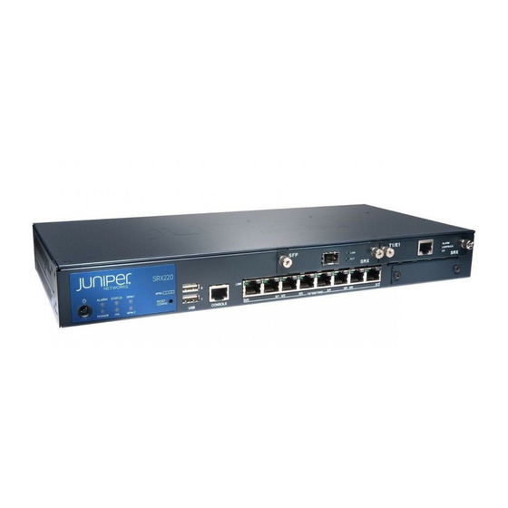
Clearance Requirements for Airflow and Hardware Maintenance of the SRX220 Services Gateway on page 33 SRX220 Services Gateway Specifications The SRX220 Services Gateway chassis is a rigid sheet metal structure of 1 rack unit (U) height that houses all the other hardware components. Figure 7 on page 30 shows the SRX220 Services Gateway chassis for SRX220H and SRX220H-POE models. -
Page 48: Table 13: Srx220 Services Gateway Specifications
44 mm x 363 mm x 181 mm Chassis weight 4.52 lb (2.05 kg) for SRX220 models without PoE (no interface modules) 4.62 lb (2.10 kg) for SRX220 models with PoE (no interface modules) Altitude No performance degradation up to 10,000 ft... -
Page 49: Srx220 Services Gateway Cabinet Requirements
Monitoring the SRX220 Services Gateway Components Using LEDs on page 106 SRX220 Services Gateway Electrical Safety Guidelines and Warnings on page 151 SRX220 Services Gateway Cabinet Requirements The SRX220 Services Gateway can be installed in a standard 800 mm (31.5 in.) or larger enclosed cabinet. Table 14 on page 31 provides the details on cabinet size, clearance, and airflow requirements. -
Page 50: Srx220 Services Gateway Rack Requirements
SRX220 Services Gateway Hardware Guide for H Model Numbers Related General Site Guidelines for Installing the SRX220 Services Gateway on page 29 Documentation SRX220 Services Gateway Rack Requirements on page 32 Clearance Requirements for Airflow and Hardware Maintenance of the SRX220 Services... -
Page 51: Clearance Requirements For Airflow And Hardware Maintenance Of The Srx220 Services Gateway
Clearance Requirements for Airflow and Hardware Maintenance of the SRX220 Services Gateway When planning the installation site for the SRX220 Services Gateway, you need to allow sufficient clearance around the rack or cabinet where you are planning to install the device. - Page 52 SRX220 Services Gateway Hardware Guide for H Model Numbers Related General Site Guidelines for Installing the SRX220 Services Gateway on page 29 Documentation SRX220 Services Gateway Cabinet Requirements on page 31 SRX220 Services Gateway Rack Requirements on page 32 Copyright © 2016, Juniper Networks, Inc.
-
Page 53: Power Requirements And Specifications
CHAPTER 7 Power Requirements and Specifications SRX220 Services Gateway Site Electrical Wiring Guidelines on page 35 SRX220 Services Gateway Electrical and Power Requirements on page 36 SRX220 Services Gateway Power Specifications and Requirements on page 37 SRX220 Services Gateway Site Electrical Wiring Guidelines... -
Page 54: Srx220 Services Gateway Electrical And Power Requirements
The shielding for the wiring must be grounded at both ends. Related General Site Guidelines for Installing the SRX220 Services Gateway on page 29 Documentation SRX220 Services Gateway Electrical and Power Requirements on page 36... -
Page 55: Srx220 Services Gateway Power Specifications And Requirements
SRX220 Services Gateway Power Supply on page 23 Documentation SRX220 Services Gateway Site Electrical Wiring Guidelines on page 35 SRX220 Services Gateway Grounding Specifications on page 65 Interface Cable and Wire Specifications for the SRX220 Services Gateway on page 39 Copyright © 2016, Juniper Networks, Inc. - Page 56 SRX220 Services Gateway Hardware Guide for H Model Numbers Copyright © 2016, Juniper Networks, Inc.
-
Page 57: Cable Specifications And Pinouts
CHAPTER 8 Cable Specifications and Pinouts Interface Cable and Wire Specifications for the SRX220 Services Gateway on page 39 RJ-45 Connector Pinouts for the SRX220 Services Gateway Ethernet Port on page 39 RJ-45 Connector Pinouts for the SRX220 Services Gateway Console Port on page 40... -
Page 58: Rj-45 Connector Pinouts For The Srx220 Services Gateway Console Port
BI_DD+ BI_DD- Related Interface Cable and Wire Specifications for the SRX220 Services Gateway on page 39 Documentation RJ-45 Connector Pinouts for the SRX220 Services Gateway Console Port on page 40 RJ-45 Connector Pinouts for the SRX220 Services Gateway Console Port Figure 9 on page 40 shows the RJ-45 connector pinouts for the console port. -
Page 59: Cable Specifications And Pinouts
Data Set Ready Clear to Send Related Interface Cable and Wire Specifications for the SRX220 Services Gateway on page 39 Documentation RJ-45 Connector Pinouts for the SRX220 Services Gateway Ethernet Port on page 39 Copyright © 2016, Juniper Networks, Inc. - Page 60 SRX220 Services Gateway Hardware Guide for H Model Numbers Copyright © 2016, Juniper Networks, Inc.
-
Page 61: Initial Installation And Configuration
Installing the Services Gateway on page 57 Grounding the SRX220 Services Gateway on page 65 Connecting the SRX220 Services Gateway to External Devices on page 69 Providing Power to the SRX220 Services Gateway on page 73 Performing Initial Configuration on page 77... - Page 62 SRX220 Services Gateway Hardware Guide for H Model Numbers Copyright © 2016, Juniper Networks, Inc.
-
Page 63: Installation Overview
CHAPTER 9 Installation Overview Installation Overview for the SRX220 Services Gateway on page 45 Required Tools and Parts for Installing and Maintaining the SRX220 Services Gateway on page 46 SRX220 Services Gateway Autoinstallation Overview on page 47 Installation Overview for the SRX220 Services Gateway After you have prepared your installation site, you are ready to unpack and install the services gateway. -
Page 64: Gateway
Related Unpacking the SRX220 Services Gateway on page 49 Documentation General Site Guidelines for Installing the SRX220 Services Gateway on page 29 Preparing the SRX220 Services Gateway for Rack-Mount and Wall-Mount Installation on page 53 Required Tools and Parts for Installing and Maintaining the SRX220 Services Gateway... -
Page 65: Srx220 Services Gateway Autoinstallation Overview
Unpacking the SRX220 Services Gateway on page 49 Documentation Grounding the SRX220 Services Gateway on page 66 Connecting the SRX220 Services Gateway to the Power Supply on page 73 Packing the SRX220 Services Gateway and Components for Shipment on page 121 SRX220 Services Gateway Autoinstallation Overview The autoinstallation process begins any time a services gateway is powered on and cannot locate a valid configuration file in the CompactFlash memory. - Page 66 SRX220 Services Gateway Hardware Guide for H Model Numbers Powering On and Powering Off the SRX220 Services Gateway on page 74 Copyright © 2016, Juniper Networks, Inc.
-
Page 67: Unpacking The Services Gateway
Verifying Parts Received with the SRX220 Services Gateway on page 49 Unpacking the SRX220 Services Gateway The SRX220 Services Gateway is shipped in a cardboard box. The carton also contains the device accessories and the SRX220 Services Gateway Quick Start. -
Page 68: Table 24: Parts List For A Fully Configured Srx220 Services Gateway
SRX220 Services Gateway Hardware Guide for H Model Numbers If any part is missing, contact your Juniper Networks customer service representative. The shipment contains a fully configured SRX220 Services Gateway, including the chassis with installed components listed in Table 24 on page... - Page 69 You must order them separately. Contact your Juniper Networks customer service representative for more information. Related Required Tools and Parts for Installing and Maintaining the SRX220 Services Gateway Documentation on page 46 Unpacking the SRX220 Services Gateway on page 49...
- Page 70 SRX220 Services Gateway Hardware Guide for H Model Numbers Copyright © 2016, Juniper Networks, Inc.
-
Page 71: Installing The Mounting Hardware
Preparing the SRX220 Services Gateway for Wall-Mount Installation on page 54 Preparing the SRX220 Services Gateway for Rack-Mount and Wall-Mount Installation You can mount an SRX220 Services Gateway in a rack or on a wall. See the following topics for more information:... -
Page 72: Preparing The Srx220 Services Gateway For Wall-Mount Installation
Preparing the SRX220 Services Gateway for Wall-Mount Installation on page 54 Preparing the SRX220 Services Gateway for Wall-Mount Installation You can mount an SRX220 Services Gateway on a wall. The four rubber feet attached to the chassis provide stability. Table 27 on page 55 provides the list of tasks you need to perform before installing the device on a wall. -
Page 73: Table 27: Srx220 Services Gateway Preinstallation Checklist For Wall-Mount
The wall-mounting kit is not shipped with the device and must be ordered separately. Related Unpacking the SRX220 Services Gateway on page 49 Documentation Preparing the SRX220 Services Gateway for Rack-Mount Installation on page 53 Copyright © 2016, Juniper Networks, Inc. - Page 74 SRX220 Services Gateway Hardware Guide for H Model Numbers Copyright © 2016, Juniper Networks, Inc.
-
Page 75: Installing The Services Gateway
Gateway on page 62 Installing the SRX220 Services Gateway in a Rack You can front-mount the SRX220 Services Gateway in a rack. Many types of racks are acceptable, including four-post (telco) racks, enclosed cabinets, and open-frame racks. For more information about the type of rack or cabinet into which theSRX220 Services Gateway can be installed, see “SRX220 Services Gateway Rack Requirements”... -
Page 76: Figure 10: Installation Of Srx220 Services Gateway In A Rack - Attaching The Mounting Brackets
Position a mounting bracket on each side of the chassis, as shown in Figure 10 on page Figure 10: Installation of SRX220 Services Gateway in a Rack — Attaching the Mounting Brackets Use a number-1 Phillips screwdriver to install the screws that secure the mounting... -
Page 77: Figure 12: Positioning The Power Supply In The Tray (Standard Model)
Have one person grasp the sides of the device, lift it, and position it in the rack. Align the bottom hole in each mounting bracket with a hole in each rack rail, as shown Figure 14 on page 60, making sure the chassis is level. Copyright © 2016, Juniper Networks, Inc. -
Page 78: Installing The Srx220 Services Gateway On A Wall
Related SRX220 Services Gateway General Safety Guidelines and Warnings on page 127 Documentation Required Tools and Parts for Installing and Maintaining the SRX220 Services Gateway on page 46 Preparing the SRX220 Services Gateway for Rack-Mount Installation on page 53 Installing the SRX220 Services Gateway on a Wall on page 60 Installing the SRX220 Services Gateway on a Wall You can install the SRX220 Services Gateway on a wall. -
Page 79: Figure 15: Srx220 Services Gateway Wall Installation - Attaching The Mounting
To install the device on a wall: Place the device on a flat and level surface with the Juniper Networks logo embossed on the top cover facing up. Ensure that the rubber feet are attached to the bottom of the chassis. -
Page 80: Gateway
They enable you to easily add or change physical interfaces on a device. The SRX220 Services Gateway has two Mini-PIM slots. Each slot is covered with a blank faceplate to maintain proper airflow through the services gateway. Before installing a Mini-PIM in a slot, you must remove the blank faceplate from the slot. - Page 81 Chapter 12: Installing the Services Gateway Related SRX220 Services Gateway Installation Safety Guidelines and Warnings on page 135 Documentation Installing the SRX220 Services Gateway on a Wall on page 60 Installing the SRX220 Services Gateway in a Rack on page 57...
- Page 82 SRX220 Services Gateway Hardware Guide for H Model Numbers Copyright © 2016, Juniper Networks, Inc.
-
Page 83: Grounding The Srx220 Services Gateway
Up to 4 A Grounding lug Ring-type, vinyl-insulated TV14-6R lug or equivalent Related SRX220 Services Gateway Site Electrical Wiring Guidelines on page 35 Documentation SRX220 Services Gateway Power Specifications and Requirements on page 37 Grounding the SRX220 Services Gateway on page 66... -
Page 84: Grounding The Srx220 Services Gateway
SRX220 Services Gateway Hardware Guide for H Model Numbers Interface Cable and Wire Specifications for the SRX220 Services Gateway on page 39 Grounding the SRX220 Services Gateway To meet safety and electromagnetic interference (EMI) requirements and to ensure proper operation, you must adequately ground the SRX220 Services Gateway before connecting power. - Page 85 NOTE: The device should be permanently connected to ground during normal operation. Related Connecting the SRX220 Services Gateway to the Power Supply on page 73 Documentation Connecting and Organizing Interface Cables for the SRX220 Services Gateway on page 69 SRX220 Services Gateway Grounding Specifications on page 65...
- Page 86 SRX220 Services Gateway Hardware Guide for H Model Numbers Copyright © 2016, Juniper Networks, Inc.
-
Page 87: Connecting The Srx220 Services Gateway To External Devices
Connecting the Modem to the Console Port on the SRX220 Services Gateway on page 70 Connecting to the CLI at the User End for the SRX220 Services Gateway on page 70 Connecting and Organizing Interface Cables for the SRX220 Services Gateway You can connect the interfaces installed in the services gateway to various network media. -
Page 88: Gateway
Configuring the Modem at the SRX220 Services Gateway End on page 98 Documentation Connecting to the CLI at the User End for the SRX220 Services Gateway on page 70 SRX220 Services Gateway Software Configuration Overview on page 77 Connecting to the CLI at the User End for the SRX220 Services Gateway... -
Page 89: Table 31: Port Settings For Connecting To The Cli At User End
Related Configuring the Modem at the SRX220 Services Gateway End on page 98 Documentation Connecting the Modem to the Console Port on the SRX220 Services Gateway on page 70 SRX220 Services Gateway Software Configuration Overview on page 77 Copyright © 2016, Juniper Networks, Inc. - Page 90 SRX220 Services Gateway Hardware Guide for H Model Numbers Copyright © 2016, Juniper Networks, Inc.
-
Page 91: Providing Power To The Srx220 Services Gateway
Providing Power to the SRX220 Services Gateway Connecting the SRX220 Services Gateway to the Power Supply on page 73 Powering On and Powering Off the SRX220 Services Gateway on page 74 Connecting the SRX220 Services Gateway to the Power Supply... -
Page 92: Powering On And Powering Off The Srx220 Services Gateway
This noise is temporary and stops after the device is configured. Related Required Tools and Parts for Installing and Maintaining the SRX220 Services Gateway Documentation on page 46 Grounding the SRX220 Services Gateway on page 66... -
Page 93: Powering Off The Srx220 Services Gateway
Chapter 15: Providing Power to the SRX220 Services Gateway Powering Off the SRX220 Services Gateway You can power off the services gateway in one of the following ways: Graceful shutdown—Press and release the Power button. The device begins gracefully shutting down the operating system and then powers itself off. -
Page 94: Resetting The Srx220 Services Gateway
Connecting the SRX220 Services Gateway to the Power Supply on page 73 Documentation Grounding the SRX220 Services Gateway on page 66 Using the Reset Config Button on the SRX220 Services Gateway on page 112 Copyright © 2016, Juniper Networks, Inc. -
Page 95: Performing Initial Configuration
Connecting to the SRX220 Services Gateway Setup Wizard on page 81 SRX220 Services Gateway Secure Web Access Overview on page 82 Connecting an SRX220 Services Gateway to the CLI Locally on page 83 Connecting an SRX220 Services Gateway to the CLI Remotely on page 85... -
Page 96: Understanding The Factory-Default Configuration
SRX220 Services Gateway Hardware Guide for H Model Numbers Before configuring the device, gather the configuration information required to deploy the device in your network. At minimum, the setup wizard requires the following information: Device name to be used on the network... -
Page 97: Mapping The Chassis Cluster Ports
Table 32 on page 79 shows the mapping of the chassis cluster ports. Table 32: Mapping of the Chassis Cluster Ports on an SRX220 Services Gateway GE Port on SRX220 Services Gateway Management Interface... -
Page 98: Understanding Management Access
Configuration Guides for Junos OS Public Sector Certifications Related Connecting an SRX220 Services Gateway to the CLI Locally on page 83 Documentation Connecting an SRX220 Services Gateway to the CLI Remotely on page 85 Performing Initial Software Configuration on the SRX220 Services Gateway Using the... -
Page 99: Connecting To The Srx220 Services Gateway Setup Wizard
Chapter 16: Performing Initial Configuration Connecting to the SRX220 Services Gateway Setup Wizard If you plan to use the setup wizard to configure the SRX220 Services Gateway, you must connect your management device (such as a laptop or desktop computer) to one of the... -
Page 100: Srx220 Services Gateway Secure Web Access Overview
IP address in the address field. 192.168.1.1 Related Connecting an SRX220 Services Gateway to the CLI Locally on page 83 Documentation SRX220 Services Gateway Software Configuration Overview on page 77 SRX220 Services Gateway Secure Web Access Overview on page 82 SRX220 Services Gateway Secure Web Access Overview You can manage a services gateway remotely through the J-Web interface. -
Page 101: Connecting An Srx220 Services Gateway To The Cli Locally
Chapter 16: Performing Initial Configuration Connecting an SRX220 Services Gateway to the CLI Locally If you plan to use the command-line interface (CLI) to configure the SRX220 Services Gateway, you must connect through the console port, as shown in Figure 20 on page... -
Page 102: Table 34: Port Settings For Connecting To The Console Port
. No password is required at initial connection, but you must assign a root password before committing any configuration settings. Related Connecting an SRX220 Services Gateway to the CLI Remotely on page 85 Documentation Performing Initial Software Configuration on the SRX220 Services Gateway Using the... -
Page 103: Connecting An Srx220 Services Gateway To The Cli Remotely
Chapter 16: Performing Initial Configuration Connecting an SRX220 Services Gateway to the CLI Remotely You can connect an SRX220 Services Gateway to the CLI from a remote location through two dial-up modems: A modem that is connected to the console port on the services gateway... - Page 104 SRX220 Services Gateway Hardware Guide for H Model Numbers srx110b-vb-factory.conf srx220h2-poe-factory.conf srx110b-wl-defaults.conf srx240-16xge-factory.conf srx110b-wl-factory.conf srx240-poe-16xge-factory.conf srx110h-defaults.conf srx240b-factory.conf srx110h-va-defaults.conf srx240b2-factory.conf srx110h-va-factory.conf srx240h-dc-defaults.conf srx110h-va-wl-defaults.conf srx240h-dc-factory.conf srx110h-va-wl-factory.conf srx240h-defaults.conf srx110h-vb-defaults.conf srx240h-factory.conf srx110h-vb-factory.conf srx240h-poe-defaults.conf srx110h-vb-wl-defaults.conf srx240h-poe-factory.conf srx110h-vb-wl-factory.conf srx240h2-dc-defaults.conf srx110h-wl-defaults.conf srx240h2-dc-factory.conf srx110h-wl-factory.conf srx240h2-defaults.conf srx110h2-va-defaults.conf srx240h2-factory.conf srx110h2-va-factory.conf srx240h2-poe-defaults.conf...
- Page 105 0 { family ethernet-switching { vlan { members vlan-trust; ge-0/0/2 { unit 0 { family ethernet-switching { vlan { members vlan-trust; ge-0/0/3 { unit 0 { family ethernet-switching { vlan { members vlan-trust; Copyright © 2016, Juniper Networks, Inc.
- Page 106 SRX220 Services Gateway Hardware Guide for H Model Numbers ge-0/0/4 { unit 0 { family ethernet-switching { vlan { members vlan-trust; ge-0/0/5 { unit 0 { family ethernet-switching { vlan { members vlan-trust; ge-0/0/6 { unit 0 { family ethernet-switching { vlan { members vlan-trust;...
- Page 107 0 { family ethernet-switching { vlan { members vlan-trust; ge-0/0/14 { unit 0 { family ethernet-switching { vlan { members vlan-trust; ge-0/0/15 { unit 0 { family ethernet-switching { vlan { members vlan-trust; Copyright © 2016, Juniper Networks, Inc.
- Page 108 SRX220 Services Gateway Hardware Guide for H Model Numbers vlan { unit 0 { family inet { address 192.168.1.1/24; poe { interface all; security { nat { source { rule-set trust-to-untrust { from zone trust; to zone untrust; rule source-nat-rule { match { source-address 0.0.0.0/0;...
- Page 109 Related SRX220 Services Gateway Software Configuration Overview on page 77 Documentation SRX220 Services Gateway Autoinstallation Overview on page 47 Performing Initial Software Configuration on the SRX220 Services Gateway Using the CLI on page 92 Copyright © 2016, Juniper Networks, Inc.
-
Page 110: Performing Initial Software Configuration On The Srx220 Services Gateway
SRX220 Services Gateway Hardware Guide for H Model Numbers Performing Initial Software Configuration on the SRX220 Services Gateway Using the This procedure connects the device to the network but does not enable it to forward traffic. For complete information about enabling the device to forward traffic, including examples, see the appropriate Junos OS configuration guides. - Page 111 [ lab.device.net device.net ]; backup-device 192.168.2.44; time-zone America/Los_Angeles; root-authentication { ssh-rsa "ssh-rsa AAAAB3Nza...D9Y2gXF9ac==root@devicea.lab.device.net"; name-server { 10.148.2.32; services { ntp { server 10.148.2.21; interfaces { ge-0/0/0 { unit 0 { Copyright © 2016, Juniper Networks, Inc.
-
Page 112: Performing Initial Software Configuration On The Srx220 Services Gateway Using The J-Web Interface Setup Wizard
[edit] admin@device# exit admin@device> Related Connecting an SRX220 Services Gateway to the CLI Locally on page 83 Documentation Connecting an SRX220 Services Gateway to the CLI Remotely on page 85 SRX220 Services Gateway Software Configuration Overview on page 77 SRX220 Services Gateway Secure Web Access Overview on page 82... - Page 113 VLANs Interfaces Table 35 on page 96 Table 36 on page 97 for a summary of the required and optional configuration details. Click Commit on the Review & Commit page to apply the configuration. Copyright © 2016, Juniper Networks, Inc.
-
Page 114: Configuring Basic System Properties
SRX220 Services Gateway Hardware Guide for H Model Numbers NOTE: After configuring the basic settings, the J-Web setup wizard redirects you to J-Web pages where you can continue working in the J-Web interface. After you complete initial setup configuration, the Setup Wizard is no longer available. -
Page 115: Table 36: Optional Setup Fields
Choose Configure > Wizards to use the available wizards. Use the J-Web interface or the CLI for more extensive configuration. For more instructions on managing users and operations, monitoring network performance, upgrading software, and diagnosing common problems on an SRX220 Services Gateway, Initial Configuration for Security Devices Related... -
Page 116: Configuring The Modem At The Srx220 Services Gateway End
SRX220 Services Gateway Hardware Guide for H Model Numbers Configuring the Modem at the SRX220 Services Gateway End NOTE: These instructions use Hayes-compatible modem commands to configure the modem. If your modem is not Hayes-compatible, refer to the documentation for your modem and enter the equivalent modem commands. -
Page 117: Configuring Poe Functionality On The Srx220 Services Gateway
Connecting the Modem to the Console Port on the SRX220 Services Gateway on Documentation page 70 Connecting to the CLI at the User End for the SRX220 Services Gateway on page 70 SRX220 Services Gateway Software Configuration Overview on page 77 Configuring PoE Functionality on the SRX220 Services Gateway To enable the Power over Ethernet (PoE) feature support on your SRX220 Services Gateway, you must configure the services gateway. - Page 118 SRX220 Services Gateway Hardware Guide for H Model Numbers Copyright © 2016, Juniper Networks, Inc.
-
Page 119: Maintaining And Troubleshooting Components
PART 4 Maintaining and Troubleshooting Components Maintaining Components on page 103 Troubleshooting Components on page 105 Copyright © 2016, Juniper Networks, Inc. - Page 120 SRX220 Services Gateway Hardware Guide for H Model Numbers Copyright © 2016, Juniper Networks, Inc.
-
Page 121: Maintaining Components
CHAPTER 17 Maintaining Components Maintaining the SRX220 Services Gateway Hardware Components on page 103 Maintaining the SRX220 Services Gateway Hardware Components Table 38 on page 103 describes the common tasks for maintaining the hardware components of the services gateway. Table 38: Maintenance Procedures for Services Gateway Hardware... - Page 122 SRX220 Services Gateway Hardware Guide for H Model Numbers Related Connecting the SRX220 Services Gateway to the Power Supply on page 73 Documentation Clearance Requirements for Airflow and Hardware Maintenance of the SRX220 Services Gateway on page 33 Copyright © 2016, Juniper Networks, Inc.
-
Page 123: Troubleshooting Components
Monitoring the SRX220 Services Gateway Power System on page 110 Resetting the SRX220 Services Gateway on page 111 Using the Reset Config Button on the SRX220 Services Gateway on page 112 Changing the Reset Config Button Behavior on the SRX220 Services... -
Page 124: Monitoring The Srx220 Services Gateway Components Using Leds
Monitoring the SRX220 Services Gateway Components Using LEDs on page 106 Documentation Monitoring the SRX220 Services Gateway Using Chassis Alarm Conditions on page 109 Monitoring the SRX220 Services Gateway Power System on page 110 Maintaining the SRX220 Services Gateway Hardware Components on page 103... -
Page 125: Table 39: Component Leds On The Services Gateway
The device is starting up. Normal condition. No action is required. NOTE: If the system is up and running and the Alarm LED is off, it indicates that no alarms are present on the device. Copyright © 2016, Juniper Networks, Inc. - Page 126 Monitoring the SRX220 Services Gateway Using Chassis Alarm Conditions on page 109 Monitoring the SRX220 Services Gateway Power System on page 110 Using the Reset Config Button on the SRX220 Services Gateway on page 112 Changing the Reset Config Button Behavior on the SRX220 Services Gateway on...
-
Page 127: Monitoring The Srx220 Services Gateway Using Chassis Alarm Conditions
For more information on the show chassis alarms command, see the Initial Configuration for Security Devices Table 40 on page 109 describes alarms that can occur for an SRX220 Services Gateway chassis component. Table 40: SRX220 Services Gateway Chassis Alarm Conditions and Corrective Actions... -
Page 128: Monitoring The Srx220 Services Gateway Power System
Monitoring the SRX220 Services Gateway Components Using LEDs on page 106 Monitoring the SRX220 Services Gateway Power System on page 110 Using the Reset Config Button on the SRX220 Services Gateway on page 112 Changing the Reset Config Button Behavior on the SRX220 Services Gateway on... -
Page 129: Resetting The Srx220 Services Gateway
Monitoring the SRX220 Services Gateway Components Using LEDs on page 106 Monitoring the SRX220 Services Gateway Using Chassis Alarm Conditions on page 109 Using the Reset Config Button on the SRX220 Services Gateway on page 112 Changing the Reset Config Button Behavior on the SRX220 Services Gateway on... -
Page 130: Using The Reset Config Button On The Srx220 Services Gateway
SRX220 Services Gateway Hardware Guide for H Model Numbers Using the Reset Config Button on the SRX220 Services Gateway on page 112 Using the Reset Config Button on the SRX220 Services Gateway If a configuration fails or denies management access to the services gateway, you can use the RESET CONFIG button to restore the device to the factory-default configuration or a rescue configuration. -
Page 131: Gateway
To return the function of the RESET CONFIG button to its default behavior, remove the config-button statement from the device configuration. Related Using the Reset Config Button on the SRX220 Services Gateway on page 112 Documentation Monitoring the SRX220 Services Gateway Chassis Using the CLI on page 105... - Page 132 SRX220 Services Gateway Hardware Guide for H Model Numbers Copyright © 2016, Juniper Networks, Inc.
-
Page 133: Replacing Components
PART 5 Replacing Components Contacting Customer Support and Returning Components on page 117 Copyright © 2016, Juniper Networks, Inc. - Page 134 SRX220 Services Gateway Hardware Guide for H Model Numbers Copyright © 2016, Juniper Networks, Inc.
-
Page 135: Contacting Customer Support And Returning Components
Contacting Customer Support Once you have located the serial numbers of the services gateway or component, you can return them for repair or replacement. For this, you need to contact Juniper Networks Technical Assistance Center (JTAC). You can contact JTAC 24 hours a day, 7 days a week, using any of the following methods: On the Web: Using the Case Manager link at http://www.juniper.net/support/... -
Page 136: Return Procedure For The Srx220 Services Gateway
Locating the SRX220 Services Gateway Serial Number and Agency Labels This topic includes the following sections: Listing the SRX220 Services Gateway and Component Details with the CLI on page 119 SRX220 Services Gateway Chassis Serial Number and Agency Labels on page 119... -
Page 137: Listing The Srx220 Services Gateway And Component Details With The Cli
Most components also have a serial number ID label attached to the component body. SRX220 Services Gateway Chassis Serial Number and Agency Labels The SRX220 Services Gateway has a serial number ID and agency labels on the bottom of the chassis, as shown in Figure 21 on page 120. -
Page 138: Srx220 Services Gateway Mini-Physical Interface Module Serial Number
Contacting Customer Support on page 117 Information You Might Need to Supply to Juniper Networks Technical Assistance Center If you are returning a services gateway or hardware component to Juniper Networks for repair or replacement, obtain a Return Materials Authorization (RMA) number from Juniper Networks Technical Assistance Center (JTAC). -
Page 139: Packing The Srx220 Services Gateway And Components For Shipment
Return Procedure for the SRX220 Services Gateway on page 118 Documentation Locating the SRX220 Services Gateway Serial Number and Agency Labels on page 118 Packing the SRX220 Services Gateway and Components for Shipment on page 121 Contacting Customer Support on page 117... -
Page 140: Packing The Components For Shipment
Required Tools and Parts for Installing and Maintaining the SRX220 Services Gateway Documentation on page 46 Locating the SRX220 Services Gateway Serial Number and Agency Labels on page 118 Information You Might Need to Supply to Juniper Networks Technical Assistance Center on page 120... -
Page 141: Safety And Regulatory Compliance Information
Laser and LED Safety Guidelines and Warnings on page 141 Maintenance and Operational Safety Guidelines and Warnings on page 145 Electrical Safety Guidelines and Warnings on page 151 Agency Approvals and Regulatory Compliance Information on page 153 Copyright © 2016, Juniper Networks, Inc. - Page 142 SRX220 Services Gateway Hardware Guide for H Model Numbers Copyright © 2016, Juniper Networks, Inc.
-
Page 143: General Safety Guidelines And Warnings
SRX220 Services Gateway General Safety Guidelines and Warnings on page 127 SRX220 Services Gateway Safety Requirements, Warnings, and Guidelines on page 131 SRX220 Services Gateway Definition of Safety Warning Levels This topic defines the following four levels of safety warnings used in Juniper Networks technical publications: NOTE: You might find this information helpful in a particular situation or might otherwise overlook it. - Page 144 Documentation SRX220 Services Gateway Fire Safety Requirements on page 133 SRX220 Services Gateway Installation Safety Guidelines and Warnings on page 135 SRX220 Services Gateway Laser and LED Safety Guidelines and Warnings on page 141 Copyright © 2016, Juniper Networks, Inc.
-
Page 145: Srx220 Services Gateway General Safety Guidelines And Warnings
Chapter 20: General Safety Guidelines and Warnings SRX220 Services Gateway Electrical Safety Guidelines and Warnings on page 151 SRX220 Services Gateway Maintenance and Operational Safety Guidelines and Warnings on page 145 SRX220 Services Gateway General Safety Guidelines and Warnings General Safety Guidelines and Warnings The following guidelines help ensure your safety and protect the services gateway from damage. - Page 146 SRX220 Services Gateway Hardware Guide for H Model Numbers Varoitus Ainoastaan koulutettu ja pätevä henkilökunta saa asentaa tai vaihtaa tämän laitteen. Attention Tout installation ou remplacement de l'appareil doit être réalisé par du personnel qualifié et compétent. Warnung Gerät nur von geschultem, qualifiziertem Personal installieren oder auswechseln lassen.
- Page 147 Ett område med begränsat tillträde får endast tillträdas av servicepersonal med ett speciellt verktyg, lås och nyckel, eller annan säkerhetsanordning, och kontrolleras av den auktoritet som ansvarar för området. Preventing Electrostatic Discharge Damage to the Services Gateway Copyright © 2016, Juniper Networks, Inc.
-
Page 148: Figure 22: Placing A Component Into An Electrostatic Bag
Figure 22 on page 130. Figure 22: Placing a Component into an Electrostatic Bag Related SRX220 Services Gateway Definition of Safety Warning Levels on page 125 Documentation SRX220 Services Gateway Fire Safety Requirements on page 133 Copyright © 2016, Juniper Networks, Inc. -
Page 149: Srx220 Services Gateway Safety Requirements, Warnings, And Guidelines
Providing an exhaustive set of guidelines for working with electrical equipment is beyond the scope of this guide. Related General Site Guidelines for Installing the SRX220 Services Gateway on page 29 Documentation SRX220 Services Gateway General Safety Guidelines and Warnings on page 127... - Page 150 SRX220 Services Gateway Hardware Guide for H Model Numbers Copyright © 2016, Juniper Networks, Inc.
-
Page 151: Fire Safety Requirements
In addition, establish procedures to protect your equipment in the event of a fire emergency. Juniper Networks products should be installed in an environment suitable for electronic equipment. We recommend that fire suppression equipment be available... - Page 152 To keep warranties effective, do not use a dry chemical fire extinguisher to control a fire at or near a Juniper Networks services gateway. If a dry chemical fire extinguisher is used, the unit is no longer eligible for coverage under a service agreement.
-
Page 153: Installation Safety Guidelines And Warnings
CHAPTER 22 Installation Safety Guidelines and Warnings SRX220 Services Gateway Installation Safety Guidelines and Warnings on page 135 SRX220 Services Gateway Installation Safety Guidelines and Warnings Installation Instructions Warning WARNING: Read the installation instructions before you connect the services gateway to a power source. - Page 154 SRX220 Services Gateway Hardware Guide for H Model Numbers Ensure that the equipment rack into which the services gateway is installed is evenly and securely supported to avoid the hazardous condition that could result from uneven mechanical loading. WARNING: To prevent bodily injury when mounting or servicing the services gateway in a rack, take the following precautions to ensure that the system remains stable.
- Page 155 Les directives ci-dessous sont destinées à assurer la protection du personnel: Le rack sur lequel est monté le Juniper Networks services gateway doit être fixé à la structure du bâtiment. Si cette unité constitue la seule unité montée en casier, elle doit être placée dans le bas.
- Page 156 Vær nøye med at systemet er stabilt. Følgende retningslinjer er gitt for å verne om sikkerheten: Juniper Networks services gateway må installeres i et stativ som er forankret til bygningsstrukturen. Denne enheten bør monteres nederst i kabinettet hvis dette er den eneste enheten i kabinettet.
- Page 157 Om ställningen är försedd med stabiliseringsdon skall dessa monteras fast innan enheten installeras eller underhålls på ställningen. Related SRX220 Services Gateway Fire Safety Requirements on page 133 Documentation SRX220 Services Gateway Laser and LED Safety Guidelines and Warnings on page 141 Copyright © 2016, Juniper Networks, Inc.
- Page 158 SRX220 Services Gateway Hardware Guide for H Model Numbers Copyright © 2016, Juniper Networks, Inc.
-
Page 159: Laser And Led Safety Guidelines And Warnings
Laser and LED Safety Guidelines and Warnings SRX220 Services Gateway Laser and LED Safety Guidelines and Warnings on page 141 SRX220 Services Gateway Laser and LED Safety Guidelines and Warnings The 1-Port SFP Mini-Physical Interface Module (Mini-PIM) is equipped with laser transmitters, which are considered Class 1 Laser Products by the U.S. -
Page 160: Class 1 Led Product Warning
SRX220 Services Gateway Hardware Guide for H Model Numbers Waarschuwing Klasse-1 laser produkt. Varoitus Luokan 1 lasertuote. Attention Produit laser de classe I. Warnung Laserprodukt der Klasse 1. Avvertenza Prodotto laser di Classe 1. Advarsel Laserprodukt av klasse 1. Aviso Produto laser de classe 1. -
Page 161: Radiation From Open Port Apertures Warning
Advarsel Unngå utsettelse for stråling, og stirr ikke inn i åpninger som er åpne, fordi usynlig stråling kan emiteres fra portens åpning når det ikke er tilkoblet en fiberkabel. Copyright © 2016, Juniper Networks, Inc. - Page 162 öppningar. Related SRX220 Services Gateway Installation Safety Guidelines and Warnings on page 135 Documentation SRX220 Services Gateway Maintenance and Operational Safety Guidelines and Warnings on page 145 Copyright ©...
-
Page 163: Maintenance And Operational Safety Guidelines And Warnings
CHAPTER 24 Maintenance and Operational Safety Guidelines and Warnings SRX220 Services Gateway Maintenance and Operational Safety Guidelines and Warnings on page 145 SRX220 Services Gateway Maintenance and Operational Safety Guidelines and Warnings This topic includes the following section: Safety Guidelines and Warnings on page 145... -
Page 164: Jewelry Removal Warning
SRX220 Services Gateway Hardware Guide for H Model Numbers empfohlenen Batterietyp. Entsorgen Sie die benutzten Batterien nach den Anweisungen des Herstellers. Avvertenza Pericolo di esplosione se la batteria non è installata correttamente. Sostituire solo con una di tipo uguale o equivalente, consigliata dal produttore. -
Page 165: Lightning Activity Warning
Varoitus Älä työskentele järjestelmän parissa äläkä yhdistä tai irrota kaapeleita ukkosilmalla. Attention Ne pas travailler sur le système ni brancher ou débrancher les câbles pendant un orage. Copyright © 2016, Juniper Networks, Inc. -
Page 166: Operating Temperature Warning
C). To prevent airflow restriction, allow at least 6 in. (15.2 cm) of clearance around the ventilation openings. Waarschuwing Om te voorkomen dat welke services gateway van de Juniper Networks services gateway dan ook oververhit raakt, dient u deze niet te bedienen op een plaats waar de maximale aanbevolen ο... -
Page 167: Product Disposal Warning
15,2 cm à volta das aberturas de ventilação. ¡Atención! Para impedir que un encaminador de la serie Juniper Networks services gateway se recaliente, no lo haga funcionar en un área en la que se ο... - Page 168 Varning! Slutlig kassering av denna produkt bör skötas i enlighet med landets alla lagar och föreskrifter. Related SRX220 Services Gateway Laser and LED Safety Guidelines and Warnings on page 141 Documentation SRX220 Services Gateway Electrical Safety Guidelines and Warnings on page 151...
-
Page 169: Electrical Safety Guidelines And Warnings
CHAPTER 25 Electrical Safety Guidelines and Warnings SRX220 Services Gateway Electrical Safety Guidelines and Warnings on page 151 SRX220 Services Gateway Electrical Safety Guidelines and Warnings In Case of Electrical Accident If an electrical accident results in an injury, take the following actions in this order: Use caution. - Page 170 Related SRX220 Services Gateway Electrical and Power Requirements on page 36 Documentation SRX220 Services Gateway Maintenance and Operational Safety Guidelines and...
-
Page 171: Agency Approvals And Regulatory Compliance Information
Agency Approvals and Regulatory Compliance Information SRX220 Services Gateway Agency Approvals on page 153 SRX220 Services Gateway Compliance Statements for EMC Requirements on page 154 SRX220 Services Gateway Compliance Statements for Environmental Requirements on page 155 SRX220 Services Gateway Compliance Statements for Acoustic Noise on page 156... -
Page 172: Srx220 Services Gateway Compliance Statements For Emc Requirements
EN-61000-4-6 (2007) Immunity to Conducted Disturbances EN-61000-4-11 (2004) Voltage Dips and Sags Related SRX220 Services Gateway Electrical Safety Guidelines and Warnings on page 151 Documentation SRX220 Services Gateway Compliance Statements for EMC Requirements on page 154 SRX220 Services Gateway Compliance Statements for Environmental Requirements... -
Page 173: Srx220 Services Gateway Compliance Statements For Environmental Requirements
SRX220 Services Gateway Compliance Statements for Environmental Requirements on page 155 SRX220 Services Gateway Compliance Statements for Acoustic Noise on page 156 SRX220 Services Gateway Compliance Statements for Environmental Requirements This topic includes the compliance statement for the following environmental... -
Page 174: Srx220 Services Gateway Compliance Statements For Acoustic Noise
Translation: The maximum emitted sound pressure level is 52 dB(A) or less per EN ISO 7779. Related SRX220 Services Gateway Compliance Statements for EMC Requirements on page 154 Documentation SRX220 Services Gateway Compliance Statements for Environmental Requirements on page 155 SRX220 Services Gateway Agency Approvals on page 153 Copyright ©... -
Page 175: Index
PART 7 Index Index on page 159 Copyright © 2016, Juniper Networks, Inc. - Page 176 SRX220 Services Gateway Hardware Guide for H Model Numbers Copyright © 2016, Juniper Networks, Inc.
-
Page 177: Index
(chassis)...........70, boot media cable specifications............39 monitoring..............109 connecting through the CLI locally......83 braces, in configuration statements.........xv connecting through the CLI remotely....85 brackets settings for local CLI connection......83 angle, in syntax descriptions........xv square, in configuration statements......xv Copyright © 2016, Juniper Networks, Inc. - Page 178 SRX220 Services Gateway Hardware Guide for H Model Numbers settings for modem connection at device for initial configuration............78 remote CLI access............98 RJ-45..................40 settings for modem connection for remote CLI access................70 factory-default configuration........78, console port, RJ-45..............40 fire safety specifications.............133 conventions font conventions..............xiv...
- Page 179 JTAC..................113, RJ-45................39, information required...........120 PoE See Power over Ethernet requesting support............120 LED..................18 Juniper Networks Technical Assistance Center See Port LED JTAC TX/RX/LINK, PoE ............17 Junos OS port settings................98 CLI, connecting locally..........83 power CLI, connecting remotely..........85...
- Page 180 SRX220 Services Gateway Hardware Guide for H Model Numbers requirements services gateway................3 airflow clearance............33 autoinstallation...............47 cabinet airflow..............31 back panel................11 cabinet size................31 chassis alarms..............109 electrical................36 components...............11 geographical area............32 configuration..............77 hardware maintenance..........33 establishing secure Web access......82 power..................36 factory-default configuration........78 rack size................32 front panel................11...
- Page 181 See technical support syntax conventions..............xiv technical support contacting JTAC..............xvi temperature, acceptable range.........29 temperature, nonoperating range........29 thermal output................29 TX/RX/LINK LED..............18 wall mount installation performing...............60 preparing for..............54 warnings electrical................151 installation..............135 laser and LED..............141 maintenance and operational.........145 wire specifications..............39 Copyright © 2016, Juniper Networks, Inc.
- Page 182 SRX220 Services Gateway Hardware Guide for H Model Numbers Copyright © 2016, Juniper Networks, Inc.
Need help?
Do you have a question about the SRX220 and is the answer not in the manual?
Questions and answers