Juniper SRX240 Hardware Manual
Hide thumbs
Also See for SRX240:
- Hardware manual (178 pages) ,
- Getting started manual (4 pages) ,
- Quick start manual (2 pages)

Related Manuals for Juniper SRX240


Summary of Contents for Juniper SRX240
- Page 1 SRX240 Services Gateway Hardware Guide Modified: 2015-06-08 Copyright © 2015, Juniper Networks, Inc.
- Page 2 END USER LICENSE AGREEMENT The Juniper Networks product that is the subject of this technical documentation consists of (or is intended for use with) Juniper Networks software. Use of such software is subject to the terms and conditions of the End User License Agreement (“EULA”) posted at http://www.juniper.net/support/eula.html.
-
Page 3: Table Of Contents
SRX240 Services Gateway Description ........3... - Page 4 Power System Description ......... 25 SRX240 Services Gateway Power Supply ....... . 25 AC Power Supply (SRX240 Services Gateway) .
- Page 5 Powering Off the SRX240 Services Gateway ......75 Resetting the SRX240 Services Gateway ......76 Chapter 15 Performing Initial Configuration .
- Page 6 Gateway ............118 Juniper Networks Technical Assistance Center ......118...
- Page 7 Agency Approvals and Regulatory Compliance Information ... 169 SRX240 Services Gateway Agency Approvals ......169 SRX240 Services Gateway Compliance Statements for EMC Requirements .
- Page 8 SRX240 Services Gateway Hardware Guide viii Copyright © 2015, Juniper Networks, Inc.
-
Page 9: List Of Figures
Figure 9: SRX240 Services Gateway ........ - Page 10 Figure 19: Connecting to the Ethernet Port on an SRX240 Services Gateway . . . 84 Figure 20: Connecting an SRX240 Services Gateway to the CLI ....86...
- Page 11 Table 10: SRX240 Services Gateway Front Panel Components ....18 Table 11: SRX240 Services Gateway Port LEDs ......20 Table 12: SRX240 Services Gateway Ethernet Port LEDs .
- Page 12 Chapter 12 Grounding the SRX240 Services Gateway ......59 Table 32: Grounding Cable Specifications for the Services Gateway ..59 Table 33: Grounding Cable Specifications for the Services Gateway .
-
Page 13: About The Documentation
® To obtain the most current version of all Juniper Networks technical documentation, see the product documentation page on the Juniper Networks website at http://www.juniper.net/techpubs/ If the information in the latest release notes differs from the information in the documentation, follow the product Release Notes. -
Page 14: Table 1: Notice Icons
SRX240 Services Gateway Hardware Guide Table 1: Notice Icons Icon Meaning Description Informational note Indicates important features or instructions. Caution Indicates a situation that might result in loss of data or hardware damage. Warning Alerts you to the risk of personal injury or death. -
Page 15: Documentation Feedback
We encourage you to provide feedback, comments, and suggestions so that we can improve the documentation. You can provide feedback by using either of the following methods: Online feedback rating system—On any page at the Juniper Networks Technical Documentation site at , simply click the http://www.juniper.net/techpubs/index.html... -
Page 16: Requesting Technical Support
7 days a week, 365 days a year. Self-Help Online Tools and Resources For quick and easy problem resolution, Juniper Networks has designed an online self-service portal called the Customer Support Center (CSC) that provides you with the following features: Find CSC offerings: http://www.juniper.net/customers/support/... - Page 17 About the Documentation For international or direct-dial options in countries without toll-free numbers, see http://www.juniper.net/support/requesting-support.html Copyright © 2015, Juniper Networks, Inc. xvii...
- Page 18 SRX240 Services Gateway Hardware Guide xviii Copyright © 2015, Juniper Networks, Inc.
-
Page 19: Overview
PART 1 Overview System Overview on page 3 Hardware Components on page 9 Chassis Description on page 13 Cooling System Description on page 23 Power System Description on page 25 Copyright © 2015, Juniper Networks, Inc. - Page 20 SRX240 Services Gateway Hardware Guide Copyright © 2015, Juniper Networks, Inc.
-
Page 21: System Overview
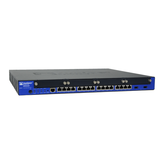
The SRX240 Services Gateway runs the Juniper Networks Junos operating system (Junos OS). The SRX240 Services Gateway has a modular 1U chassis that fits a 19-inch rack with a depth of approximately 17.5 in. (44.5 cm). Figure 1 on page 3 shows the SRX240 Services Gateway. -
Page 22: Srx240 Services Gateway Hardware Features
Power, Mini-PIMs, Port (TX/RX/Link and Port (TX/RX/Link and Port (TX/RX/Link and PoE) PoE) PoE), DC power feed LEDs. NOTE: The PoE LED is enabled only on the PoE variant of the SRX240 Services Gateway. Copyright © 2015, Juniper Networks, Inc. -
Page 23: Srx240 Services Gateway Power Over Ethernet Overview
NEBS-compliant NOTE: An air filter is not shipped with the SRX240 Services Gateway with AC power supply models. To meet NEBS requirements, you must order the air filter separately and install it. Contact your Juniper Networks customer service representative for more information. -
Page 24: Introduction
Power over Ethernet (PoE) provides a device the capability to transmit both data and electric power over a copper Ethernet LAN cable. The PoE-capable models of the SRX240 Services Gateway (see SRX240 Services Gateway Models) PoE on all Gigabit Ethernet ports. The PoE ports transfer electrical power and data, to remote devices over a standard twisted-pair cable in an Ethernet network. -
Page 25: System Overview
SRX240 Services Gateway Description on page 3 Documentation SRX240 Services Gateway Chassis on page 31 SRX240 Services Gateway Front Panel and Back Panel Views on page 13 SRX240 Services Gateway Built-In Interfaces on page 16 SRX240 Services Gateway LEDs on page 18 Mini-Physical Interface Modules for the SRX240 Services Gateway on page 9 Copyright ©... - Page 26 SRX240 Services Gateway Hardware Guide Copyright © 2015, Juniper Networks, Inc.
-
Page 27: Hardware Components
Hardware Components Mini-Physical Interface Modules for the SRX240 Services Gateway on page 9 SRX240 Services Gateway Boot Devices and Dual-Root Partitioning Scheme on page 10 Mini-Physical Interface Modules for the SRX240 Services Gateway SRX240 Services Gateway support Mini-Physical Interface Modules (Mini-PIMs). -
Page 28: Scheme
Boot Devices on page 10 Dual-Root Partitioning Scheme on page 10 Boot Devices The SRX240 Services Gateway can boot from the following storage media (in the given order of priority): Internal NAND flash memory (default; always present) USB storage device (alternate) - Page 29 Related SRX240 Services Gateway Chassis on page 31 Documentation SRX240 Services Gateway Front Panel and Back Panel Views on page 13 SRX240 Services Gateway Built-In Interfaces on page 16 SRX240 Services Gateway LEDs on page 18 SRX240 Services Gateway Power Supply on page 25 SRX240 Services Gateway Cooling System on page 23 Copyright ©...
- Page 30 SRX240 Services Gateway Hardware Guide Copyright © 2015, Juniper Networks, Inc.
-
Page 31: Chassis Description
SRX240 Services Gateway LEDs on page 18 SRX240 Services Gateway Front Panel and Back Panel Views This topic describes the front panel and back panel of the SRX240 Services Gateway models. This topic includes the following sections: SRX240 Services Gateway Front Panel on page 13... - Page 32 For more information on the front panel components, see the following topics: SRX240 Services Gateway Built-In Interfaces on page 16 SRX240 Services Gateway LEDs on page 18 SRX240 Services Gateway Boot Devices and Dual-Root Partitioning Scheme on page 10 Copyright © 2015, Juniper Networks, Inc.
-
Page 33: Srx240 Services Gateway Back Panel (Ac Power Supply Models)
The air filter is shipped with SRX240 Services Gateways with DC power supply models only. You can order the air filter separately for the SRX240 Services Gateway with AC power supply models. Contact your Juniper Networks customer service representative for more information. -
Page 34: Srx240 Services Gateway Built-In Interfaces
SRX240 Services Gateway Built-In Interfaces on page 16 SRX240 Services Gateway LEDs on page 18 SRX240 Services Gateway Boot Devices and Dual-Root Partitioning Scheme on page 10 SRX240 Services Gateway Power Supply on page 25 SRX240 Services Gateway Cooling System on page 23... - Page 35 Related SRX240 Services Gateway Chassis on page 31 Documentation SRX240 Services Gateway Front Panel and Back Panel Views on page 13 SRX240 Services Gateway LEDs on page 18 SRX240 Services Gateway Boot Devices and Dual-Root Partitioning Scheme on page 10...
-
Page 36: Srx240 Services Gateway Leds
This topic includes the following sections: Front Panel LEDs on page 18 Ethernet Port LEDs on page 20 DC Power Supply Feed LEDs (SRX240 Services Gateway DC Power Supply Model) on page 21 Front Panel LEDs Figure 5 on page 18 shows the SRX240 Services Gateway front panel LEDs. - Page 37 Chapter 3: Chassis Description Table 10: SRX240 Services Gateway Front Panel Components (continued) Component Description Usage Alarm LED The Alarm LED has the following The Alarm LED can be used to indicator colors: gather information on major or minor alarms or to determine whether the Red and steadily on indicates a device is functioning normally.
-
Page 38: Ethernet Port Leds
SRX240 Services Gateway Hardware Guide Ethernet Port LEDs On the SRX240 Services Gateway, each Gigabit Ethernet port has the two LEDs as shown Figure 6 on page Figure 6: SRX240 Services Gateway Port LEDs Table 11: SRX240 Services Gateway Port LEDs... -
Page 39: Dc Power Supply Feed Leds
DC Power Supply Feed LEDs (SRX240 Services Gateway DC Power Supply Model) On the SRX240 Services Gateway with DC power supply models, the back panel includes two LEDs, which indicate the status of the DC power supply feed. Figure 7 on page 21 shows the DC power supply feed LEDs on the SRX240 Services Gateway with DC power supply model. -
Page 40: Srx240 Services Gateway Chassis
SRX240 Services Gateway Chassis on page 31 Documentation SRX240 Services Gateway Front Panel and Back Panel Views on page 13 SRX240 Services Gateway Built-In Interfaces on page 16 SRX240 Services Gateway Boot Devices and Dual-Root Partitioning Scheme on page 10... -
Page 41: Cooling System Description
(when the chassis is viewed from the front) as shown in Figure 8 on page The airflow produced by these fans keeps all components within the acceptable temperature range. Figure 8: Airflow Through the SRX240 Services Gateway Chassis Copyright © 2015, Juniper Networks, Inc. -
Page 42: Srx240 Services Gateway Air Filter
SRX240 Services Gateway Power Supply on page 25 SRX240 Services Gateway Air Filter The air filter for the SRX240 Services Gateway (both with AC power supply models and with DC power supply models) is hot-insertable and hot-removable. The air intake opening is at the right side of the chassis (when the chassis is viewed from the front side). -
Page 43: Power System Description
This topic includes the following sections: AC Power Supply (SRX240 Services Gateway) on page 25 DC Power Supply (SRX240 Services Gateway with DC Power Supply Model) on page 25 AC Power Supply (SRX240 Services Gateway) The SRX240 Services Gateway AC power supply models use a fixed, internal AC power supply. - Page 44 SRX240 Services Gateway Hardware Guide Related Connecting the SRX240 Services Gateway DC Power Supply Model to a DC Power Documentation Source on page 70 SRX240 Services Gateway DC Power Specifications and Requirements on page 38 DC Power Electrical Safety Guidelines and Warnings on page 161...
-
Page 45: Site Planning And Specifications
PART 2 Site Planning and Specifications Planning and Preparing the Site on page 29 Power Requirements and Specifications on page 35 Cable Specifications and Pinouts on page 41 Copyright © 2015, Juniper Networks, Inc. - Page 46 SRX240 Services Gateway Hardware Guide Copyright © 2015, Juniper Networks, Inc.
-
Page 47: Planning And Preparing The Site
Planning and Preparing the Site Site Preparation Checklist for the SRX240 Services Gateway on page 29 General Site Guidelines for Installing the SRX240 Services Gateway on page 30 SRX240 Services Gateway Chassis on page 31 SRX240 Services Gateway Rack Requirements on page 33... -
Page 48: General Site Guidelines For Installing The Srx240 Services Gateway
Clearance Requirements for Airflow and Hardware Maintenance on the SRX240 Services Gateway on page 33 Interface Cable and Wire Specifications for the SRX240 Services Gateway on page 41 General Site Guidelines for Installing the SRX240 Services Gateway on page 30... -
Page 49: Srx240 Services Gateway Chassis
SRX240 Services Gateway Rack Requirements on page 33 Clearance Requirements for Airflow and Hardware Maintenance on the SRX240 Services Gateway on page 33 Interface Cable and Wire Specifications for the SRX240 Services Gateway on page 41 SRX240 Services Gateway Chassis Figure 1 on page 3 shows the SRX240 Services Gateway chassis. - Page 50 SRX240 Services Gateway Description on page 3 Documentation SRX240 Services Gateway Hardware Features on page 4 SRX240 Services Gateway Front Panel and Back Panel Views on page 13 SRX240 Services Gateway Built-In Interfaces on page 16 SRX240 Services Gateway LEDs on page 18...
-
Page 51: Srx240 Services Gateway Rack Requirements
Chapter 6: Planning and Preparing the Site SRX240 Services Gateway Rack Requirements The SRX240 Services Gateway can be installed in a rack. Many types of racks are acceptable, including front-mount racks and four-post (telco) racks. Table 16 on page 33 provides the details on rack size, clearance, and airflow requirements. -
Page 52: Table 17: Clearance Requirements For The Services Gateway
Related General Site Guidelines for Installing the SRX240 Services Gateway on page 30 Documentation SRX240 Services Gateway Rack Requirements on page 33 SRX240 Services Gateway Electrical and Power Requirements on page 36 Copyright © 2015, Juniper Networks, Inc. -
Page 53: Power Requirements And Specifications
SRX240 Services Gateway Site Electrical Wiring Guidelines on page 35 SRX240 Services Gateway Electrical and Power Requirements on page 36 SRX240 Services Gateway AC Power Specifications and Requirements on page 37 SRX240 Services Gateway DC Power Specifications and Requirements on page 38... -
Page 54: Srx240 Services Gateway Electrical And Power Requirements
Electrical wiring guidelines for the device installation site Power, connection, and power cord specifications for the device Grounding guidelines and specifications for the device Related General Site Guidelines for Installing the SRX240 Services Gateway on page 30 Documentation Copyright © 2015, Juniper Networks, Inc. -
Page 55: Srx240 Services Gateway Ac Power Specifications And Requirements
AC Power Requirement Specifications on page 37 AC Power Cord Specifications on page 37 AC Power Requirement Specifications The AC power system electrical specifications for the SRX240 Services Gateway are listed in Table 19 on page Table 19: AC Power Supply Specifications for the SRX240 Services... -
Page 56: Srx240 Services Gateway Dc Power Specifications And Requirements
SRX240 Services Gateway Grounding Specifications on page 59 SRX240 Services Gateway Power Supply on page 25 SRX240 Services Gateway DC Power Specifications and Requirements on page 38 SRX240 Services Gateway DC Power Specifications and Requirements This topic includes the following sections:... - Page 57 Documentation SRX240 Services Gateway Grounding Specifications on page 59 SRX240 Services Gateway Power Supply on page 25 Connecting the SRX240 Services Gateway DC Power Supply Model to a DC Power Source on page 70 Copyright © 2015, Juniper Networks, Inc.
- Page 58 SRX240 Services Gateway Hardware Guide Copyright © 2015, Juniper Networks, Inc.
-
Page 59: Cable Specifications And Pinouts
CHAPTER 8 Cable Specifications and Pinouts Interface Cable and Wire Specifications for the SRX240 Services Gateway on page 41 RJ-45 Connector Pinouts for the SRX240 Services Gateway Ethernet Port on page 41 RJ-45 Connector Pinouts for the SRX240 Services Gateway Console Port on page 43... -
Page 60: Table 24: Rj-45 Connector Pinouts For The Services Gateway Ethernet Port
BI_DB+ BI_DC+ BI_DC- BI_DB- BI_DD+ BI_DD- Related Interface Cable and Wire Specifications for the SRX240 Services Gateway on page 41 Documentation RJ-45 Connector Pinouts for the SRX240 Services Gateway Console Port on page 43 Copyright © 2015, Juniper Networks, Inc. -
Page 61: Connector Pinouts For The Srx240 Services Gateway Console Port
Data Set Ready Clear to Send Related Interface Cable and Wire Specifications for the SRX240 Services Gateway on page 41 Documentation RJ-45 Connector Pinouts for the SRX240 Services Gateway Ethernet Port on page 41 Copyright © 2015, Juniper Networks, Inc. - Page 62 SRX240 Services Gateway Hardware Guide Copyright © 2015, Juniper Networks, Inc.
-
Page 63: Initial Installation And Configuration
Installing the Services Gateway on page 53 Grounding the SRX240 Services Gateway on page 59 Connecting the SRX240 Services Gateway to External Devices on page 63 Providing Power to the SRX240 Services Gateway on page 69 Performing Initial Configuration on page 79... - Page 64 SRX240 Services Gateway Hardware Guide Copyright © 2015, Juniper Networks, Inc.
-
Page 65: Installation Overview
CHAPTER 9 Installation Overview Installation Overview for the SRX240 Services Gateway on page 47 Required Tools and Parts for Installing and Maintaining the SRX240 Services Gateway on page 48 SRX240 Services Gateway Autoinstallation Overview on page 49 Installation Overview for the SRX240 Services Gateway After you have prepared your installation site, you are ready to unpack and install the services gateway. -
Page 66: Gateway
SRX240 Services Gateway Safety Requirements, Warnings, and Guidelines on page 139 Documentation General Site Guidelines for Installing the SRX240 Services Gateway on page 30 Unpacking the SRX240 Services Gateway on page 51 Preparing the SRX240 Services Gateway for Installation on page 53... -
Page 67: Srx240 Services Gateway Autoinstallation Overview
Installing the SRX240 Services Gateway on page 53 Grounding the SRX240 Services Gateway on page 60 Connecting the SRX240 Services Gateway to the AC Power Source on page 69 Packing the SRX240 Services Gateway and Components for Shipment on page 128... - Page 68 Initial Configuration for Security Devices Monitoring and Troubleshooting for Security Devices Related Connecting the SRX240 Services Gateway to the AC Power Source on page 69 Documentation Grounding the SRX240 Services Gateway on page 60 Powering On and Powering Off the SRX240 Services Gateway on page 74...
-
Page 69: Unpacking The Services Gateway
Verifying Parts Received with the SRX240 Services Gateway on page 51 Unpacking the SRX240 Services Gateway The SRX240 Services Gateway is shipped in a cardboard carton and secured with foam packing material. The carton also contains an accessory box and the SRX240 Services Gateway Quick Start. -
Page 70: Table 29: Parts List For A Fully Configured Srx240 Services Gateway
SRX240 Services Gateway Hardware Guide NOTE: If any part is missing, contact your Juniper Networks customer service representative. A fully configured SRX240 Services Gateway contains the chassis with installed components, listed in Table 29 on page 52 and an accessory box, which contains the... -
Page 71: Installing The Services Gateway
Installing the SRX240 Services Gateway on page 53 Preparing the SRX240 Services Gateway for Installation You can mount an SRX240 Services Gateway in a rack. The services gateway can be mounted on four-post (telco) racks, enclosed cabinets, and open-frame racks. - Page 72 SRX240 Services Gateway Hardware Guide To install the device in a rack: Copyright © 2015, Juniper Networks, Inc.
-
Page 73: Figure 12: Installing The Srx240 Services Gateway In A Rack (Front-Mount)
Center-mount position as shown in Figure 13 on page NOTE: Positioning the brackets in the center offers greater stability. Figure 12: Installing the SRX240 Services Gateway in a Rack (Front- Mount) Figure 13: Installing the SRX240 Services Gateway in a Rack (Center- Mount) - Page 74 Related Preparing the SRX240 Services Gateway for Installation on page 53 Documentation Required Tools and Parts for Installing and Maintaining the SRX240 Services Gateway on page 48 Copyright © 2015, Juniper Networks, Inc.
- Page 75 Chapter 11: Installing the Services Gateway SRX240 Services Gateway Installation Safety Guidelines and Warnings on page 143 Copyright © 2015, Juniper Networks, Inc.
- Page 76 SRX240 Services Gateway Hardware Guide Copyright © 2015, Juniper Networks, Inc.
-
Page 77: Grounding The Srx240 Services Gateway
Amperage of grounding cable Up to 25 A Grounding lug Ring-type, vinyl-insulated TV14-6R lug or equivalent Related SRX240 Services Gateway Site Electrical Wiring Guidelines on page 35 Documentation Grounding the SRX240 Services Gateway on page 60 Copyright © 2015, Juniper Networks, Inc. -
Page 78: Grounding The Srx240 Services Gateway
SRX240 Services Gateway Power Supply on page 25 Grounding the SRX240 Services Gateway The following tools and parts are required for grounding the SRX240 Services Gateway: Grounding cable for your services gateway—The grounding cable must be minimum 14 AWG (2 mm²), minimum 90°C wire, or as permitted by the local code. - Page 79 Connecting and Organizing Interface Cables to the SRX240 Services Gateway on page 63 Connecting the SRX240 Services Gateway to the AC Power Source on page 69 Powering On and Powering Off the SRX240 Services Gateway on page 74 Copyright © 2015, Juniper Networks, Inc.
- Page 80 SRX240 Services Gateway Hardware Guide Copyright © 2015, Juniper Networks, Inc.
-
Page 81: Connecting The Srx240 Services Gateway To External Devices
Connecting the Modem to the Console Port on the SRX240 Services Gateway on page 65 Connecting to the CLI at the User End for the SRX240 Services Gateway on page 66 Connecting and Organizing Interface Cables to the SRX240 Services Gateway You connect the interfaces installed in the services gateway to various network media. -
Page 82: Connecting The Modem At The Srx240 Services Gateway End
Connecting the Modem at the SRX240 Services Gateway End Before you can connect a dial-up modem to the console port on the SRX240 Services Gateway, you must configure the modem to accept a call on the first ring and accept DTR signals. - Page 83 Connecting the SRX240 Services Gateway to the CLI on page 85 Connecting to the CLI at the User End for the SRX240 Services Gateway on page 66 Connecting the Modem to the Console Port on the SRX240 Services Gateway on...
-
Page 84: Connecting To The Cli At The User End For The Srx240 Services Gateway
SRX240 Services Gateway Hardware Guide Connecting to the CLI at the User End for the SRX240 Services Gateway To remotely connect to the CLI through a dial-up modem connected to the console port on the services gateway: Connect a modem at your remote location to a management device such as a PC or laptop computer. - Page 85 Chapter 13: Connecting the SRX240 Services Gateway to External Devices Connecting the Modem to the Console Port on the SRX240 Services Gateway on page 65 Copyright © 2015, Juniper Networks, Inc.
- Page 86 SRX240 Services Gateway Hardware Guide Copyright © 2015, Juniper Networks, Inc.
-
Page 87: Providing Power To The Srx240 Services Gateway
CHAPTER 14 Providing Power to the SRX240 Services Gateway Connecting the SRX240 Services Gateway to the AC Power Source on page 69 Connecting the SRX240 Services Gateway DC Power Supply Model to a DC Power Source on page 70 Powering On and Powering Off the SRX240 Services Gateway on page 74... -
Page 88: Power Source
63 Grounding the SRX240 Services Gateway on page 60 Powering On and Powering Off the SRX240 Services Gateway on page 74 Connecting the SRX240 Services Gateway DC Power Supply Model to a DC Power Source WARNING: DC-powered SRX240 Services Gateways are intended for installation only in a restricted access location. - Page 89 To meet safety and electromagnetic interference (EMI) requirements and to ensure proper operation, you must connect the SRX240 Services Gateway to ground before you connect it to power. You connect DC source power to the device by attaching power cables from the external DC power sources to the terminal studs on the DC power feed faceplates.
-
Page 90: Figure 16: Dc Power Feed On Srx240 Services Gateway With Dc Power Supply
SRX240 Services Gateway Hardware Guide Figure 16: DC Power Feed on SRX240 Services Gateway with DC Power Supply Model LEDs Terminal block Terminal block cover Remove the screws on the terminals using the Phillips (+) screwdriver, number 1. Save the screws. -
Page 91: Figure 17: Connecting Dc Power To The Srx240 Services Gateway With Dc Power
Chapter 14: Providing Power to the SRX240 Services Gateway Figure 17: Connecting DC Power to the SRX240 Services Gateway with DC Power Supply Model DC Ring lugs To connect to a single power source: Leave the links (jumpers) on the terminal blocks in place. -
Page 92: Powering On And Powering Off The Srx240 Services Gateway
To power on the services gateway: Ensure that you have connected the power supply to the services gateway. Insert the plug into an AC power source receptacle (for SRX240 Services Gateway with AC power supply, and PoE). Copyright © 2015, Juniper Networks, Inc. -
Page 93: Powering Off The Srx240 Services Gateway
Chapter 14: Providing Power to the SRX240 Services Gateway Attach the power cable to the DC power source (for SRX240 Services Gateway with DC power supply model). Ensure that the DC power source is connected according to the guidelines recommended in “Connecting the SRX240 Services Gateway DC... -
Page 94: Resetting The Srx240 Services Gateway
Monitoring and Troubleshooting for Security Devices Resetting the SRX240 Services Gateway The RESET CONFIG button located at the front panel of the SRX240 Services Gateway removes the current configuration and resets the device to the default configuration. The button is recessed in the front panel to prevent it from being pressed accidentally. - Page 95 Connecting and Organizing Interface Cables to the SRX240 Services Gateway on page 63 Connecting the SRX240 Services Gateway to the AC Power Source on page 69 Connecting the SRX240 Services Gateway DC Power Supply Model to a DC Power Source on page 70...
- Page 96 SRX240 Services Gateway Hardware Guide Copyright © 2015, Juniper Networks, Inc.
-
Page 97: Performing Initial Configuration
SRX240 Services Gateway Secure Web Access Overview on page 84 Connecting the SRX240 Services Gateway to the CLI on page 85 Viewing Factory Default Settings of the SRX240 Services Gateway on page 87 Performing Initial Software Configuration on the SRX240 Services Gateway Using the... -
Page 98: Understanding The Factory Default Configuration
SRX240 Services Gateway Hardware Guide Password for the root user Time information for the services gateway location: Local time zone Name or IP address of a Network Time Protocol (NTP) server, if NTP is used to set the time on the services gateway... -
Page 99: Mapping The Chassis Cluster Ports
On the SRX240 Services Gateway, the fxp1 port is not user configurable when the services gateway is operating in chassis cluster mode. Table 36 on page 81 shows the mapping of the chassis cluster ports. -
Page 100: Understanding Management Access
SRX240 Services Gateway Hardware Guide NOTE: On SRX240 Services Gateway, the fabric link connection can be any pair of Gigabit Ethernet interfaces. Junos OS automatically creates the interfaces on these ports when the fxp0 fxp1 SRX240 Services Gateway is operating in chassis cluster mode. -
Page 101: Connecting To The Srx240 Services Gateway Setup Wizard
Configuration Guides for Junos OS Public Sector Certifications Related Connecting to the SRX240 Services Gateway Setup Wizard on page 83 Documentation Connecting the SRX240 Services Gateway to the CLI on page 85 Performing Initial Software Configuration on the SRX240 Services Gateway Using the... -
Page 102: Srx240 Services Gateway Secure Web Access Overview
Setup Wizard Connecting the SRX240 Services Gateway to the CLI on page 85 Connecting to the CLI at the User End for the SRX240 Services Gateway on page 66 Connecting the Modem at the SRX240 Services Gateway End on page 64... -
Page 103: Connecting The Srx240 Services Gateway To The Cli
Connecting a Services Gateway to the CLI Remotely on page 87 Connecting the Services Gateway to the CLI Locally If you plan to use the CLI to configure the SRX240 Services Gateway, you must connect the services gateway through the console port as shown in Figure 20 on page Copyright ©... -
Page 104: Figure 20: Connecting An Srx240 Services Gateway To The Cli
SRX240 Services Gateway Hardware Guide Figure 20: Connecting an SRX240 Services Gateway to the CLI NOTE: Figure 20 on page 86 shows a connection to a local management device. A remote connection to the services gateway through a modem requires the cable and connector shown (provided in the services gateway accessory box), plus a DB-9 male to DB-25 male (or similar) adapter for your modem, which you must purchase separately. -
Page 105: Connecting A Services Gateway To The Cli Remotely
Connecting to the SRX240 Services Gateway Setup Wizard on page 83 Documentation Connecting to the CLI at the User End for the SRX240 Services Gateway on page 66 Connecting the Modem at the SRX240 Services Gateway End on page 64... - Page 106 SRX240 Services Gateway Hardware Guide In shell mode, navigate to the folder. /etc/config % cd /etc/config View the list of default config files. % ls The following sample output displays the list of factory default configuration files: j-series-defaults.conf srx210h-defaults.conf jsrxsme-series-defaults.conf srx210h-factory.conf...
- Page 107 Chapter 15: Performing Initial Configuration % vi srx240-poe-16xge-factory.conf The following sample output displays the factory default configuration on an SRX240 Services Gateway: ## $Id: $ ## Copyright (c) 2009, Juniper Networks, Inc. ## All rights reserved. system { autoinstallation { delete-upon-commit;...
- Page 108 SRX240 Services Gateway Hardware Guide ge-0/0/1 { unit 0 { family ethernet-switching { vlan { members vlan-trust; ge-0/0/2 { unit 0 { family ethernet-switching { vlan { members vlan-trust; ge-0/0/3 { unit 0 { family ethernet-switching { vlan { members vlan-trust;...
- Page 109 0 { family ethernet-switching { vlan { members vlan-trust; ge-0/0/11 { unit 0 { family ethernet-switching { vlan { members vlan-trust; ge-0/0/12 { unit 0 { family ethernet-switching { vlan { members vlan-trust; Copyright © 2015, Juniper Networks, Inc.
- Page 110 SRX240 Services Gateway Hardware Guide ge-0/0/13 { unit 0 { family ethernet-switching { vlan { members vlan-trust; ge-0/0/14 { unit 0 { family ethernet-switching { vlan { members vlan-trust; ge-0/0/15 { unit 0 { family ethernet-switching { vlan { members vlan-trust;...
- Page 111 { interfaces { ge-0/0/0.0 { host-inbound-traffic { system-services { dhcp; tftp; screen untrust-screen; policies { from-zone trust to-zone untrust { policy trust-to-untrust { match { source-address any; destination-address any; application any; then { permit; Copyright © 2015, Juniper Networks, Inc.
-
Page 112: Using The Cli
SRX240 Services Gateway Software Configuration Overview on page 79 Documentation SRX240 Services Gateway Autoinstallation Overview on page 49 Performing Initial Software Configuration on the SRX240 Services Gateway Using the CLI on page 94 Performing Initial Software Configuration on the SRX240 Services Gateway Using the... - Page 113 0.0.0.0/0 destination-address 0.0.0.0/0 admin@# set security nat source rule-set interface-nat rule rule1 then source-nat interface Check the configuration for validity: [edit] admin@# commit check configuration check succeeds Copyright © 2015, Juniper Networks, Inc.
- Page 114 SRX240 Services Gateway Hardware Guide Commit the configuration to activate it on the services gateway: [edit] admin@# commit commit complete Optionally, display the configuration to verify that it is correct: [edit] user@host# show system { host-name devicea; domain-name lab.device.net; domain-search [ lab.device.net device.net ];...
-
Page 115: Performing Initial Software Configuration On The Srx240 Services Gateway Using The J-Web Interface
Chapter 15: Performing Initial Configuration admin@host# exit admin@host> Related Connecting the SRX240 Services Gateway to the CLI on page 85 Documentation Performing Initial Software Configuration on the SRX240 Services Gateway Using the Setup Wizard SRX240 Services Gateway Software Configuration Overview on page 79... -
Page 116: Configuring Basic System Properties
SRX240 Services Gateway Hardware Guide Access the J-Web interface: Launch a Web browser from the management device. NOTE: To access the J-Web interface, your management device requires a supported browser: either Microsoft Internet Explorer version 7.0 (or later) or Mozilla Firefox version 3.0 (or later). -
Page 117: Table 38: Required Setup Fields
IP addresses and click Add. Domain Search Type the IP address or domain name of each domain that includes the services gateway to include it in a DNS search Copyright © 2015, Juniper Networks, Inc. - Page 118 Choose Configure > Wizards to use the available wizards. Use the J-Web interface or the CLI for more extensive configuration. For more instructions on managing users and operations, monitoring network performance, upgrading software, and diagnosing common problems on an SRX240 Services Gateway, see the following guides: Initial Configuration for Security Devices...
-
Page 119: Configuring Poe Functionality On The Srx240 Services Gateway
SRX240 Services Gateway Secure Web Access Overview on page 84 Configuring PoE Functionality on the SRX240 Services Gateway To enable the PoE feature support on your SRX240 Services Gateway, you must configure the services gateway. You can configure PoE using the CLI configuration editor. - Page 120 SRX240 Services Gateway Hardware Guide Copyright © 2015, Juniper Networks, Inc.
-
Page 121: Maintaining And Troubleshooting Components
PART 4 Maintaining and Troubleshooting Components Maintaining Components on page 105 Troubleshooting Components on page 107 Copyright © 2015, Juniper Networks, Inc. - Page 122 SRX240 Services Gateway Hardware Guide Copyright © 2015, Juniper Networks, Inc.
-
Page 123: Maintaining Components
CHAPTER 16 Maintaining Components Maintaining the SRX240 Services Gateway Hardware Components on page 105 Maintaining the SRX240 Services Gateway Hardware Components Table 40 on page 105 describes the common tasks to maintain the hardware components of the services gateway. Table 40: Maintenance Procedures for the Services Gateway Hardware... - Page 124 Monitoring the SRX240 Services Gateway Components Using LEDs on page 107 Documentation Monitoring the SRX240 Services Gateway Using Chassis Alarm Conditions on page 113 Monitoring the SRX240 Services Gateway Power System on page 115 Copyright © 2015, Juniper Networks, Inc.
-
Page 125: Troubleshooting Components
Troubleshooting Components Monitoring the SRX240 Services Gateway Components Using LEDs on page 107 Monitoring the SRX240 Services Gateway Chassis Using the CLI on page 111 Monitoring the SRX240 Services Gateway Using Chassis Alarm Conditions on page 113 Monitoring the SRX240 Services Gateway Power System on page 115... - Page 126 SRX240 Services Gateway Hardware Guide Table 41: Component LEDs on the SRX240 Services Gateway (continued) Possible Causes and State Meaning Corrective Actions Alarm LED The services gateway A major alarm indicates a detects a major alarm. critical situation on the gateway that requires immediate action.
- Page 127 Chapter 17: Troubleshooting Components Table 41: Component LEDs on the SRX240 Services Gateway (continued) Possible Causes and State Meaning Corrective Actions HA LED The device is not part of the chassis cluster setup. Mini-PIM LED Green The Mini-PIM is present and Normal condition.
- Page 128 SRX240 Services Gateway Hardware Guide Table 41: Component LEDs on the SRX240 Services Gateway (continued) Possible Causes and State Meaning Corrective Actions DC Power Green Output is normal. Normal condition. No action System Feeds is required. LEDs Red (blinking) The port has detected a Input is connected but has failure.
-
Page 129: Monitoring The Srx240 Services Gateway Chassis Using The Cli
Chapter 17: Troubleshooting Components Related Monitoring the SRX240 Services Gateway Chassis Using the CLI on page 111 Documentation Monitoring the SRX240 Services Gateway Using Chassis Alarm Conditions on page 113 Monitoring the SRX240 Services Gateway Power System on page 115... - Page 130 Monitoring the SRX240 Services Gateway Components Using LEDs on page 107 Documentation Monitoring the SRX240 Services Gateway Using Chassis Alarm Conditions on page 113 Monitoring the SRX240 Services Gateway Power System on page 115 Copyright © 2015, Juniper Networks, Inc.
-
Page 131: Monitoring The Srx240 Services Gateway Using Chassis Alarm Conditions
Chapter 17: Troubleshooting Components Monitoring the SRX240 Services Gateway Using Chassis Alarm Conditions When the services gateway detects an alarm condition, the Alarm LED on the front panel turns red or yellow as appropriate. To view a more detailed description of the cause of the alarm, issue the... - Page 132 Related Monitoring the SRX240 Services Gateway Chassis Using the CLI on page 111 Documentation Monitoring the SRX240 Services Gateway Components Using LEDs on page 107 Monitoring the SRX240 Services Gateway Power System on page 115...
-
Page 133: Monitoring The Srx240 Services Gateway Power System
Monitoring the SRX240 Services Gateway DC Power System on page 116 Monitoring the SRX240 Services Gateway AC Power System The LEDs on the SRX240 Services Gateway enable you to determine its performance and operation. The Power LED, located on the front panel of the services gateway, indicates different conditions with respect to the power system. -
Page 134: Monitoring The Srx240 Services Gateway Dc Power System
SRX240 Services Gateway Hardware Guide Monitoring the SRX240 Services Gateway DC Power System The back panel of an SRX240 Services Gateway with DC power supply model has two LEDs that indicate the status of the dual feed for the integrated DC power supply. -
Page 135: Loading The Rescue Configuration On The Srx240 Services Gateway
Performing Initial Software Configuration on the SRX240 Services Gateway Using the CLI on page 94 Related Changing the Reset Config Button Behavior on the SRX240 Services Gateway on Documentation page 118 SRX240 Services Gateway Software Configuration Overview on page 79... -
Page 136: Changing The Reset Config Button Behavior On The Srx240 Services
To return the function of the RESET CONFIG button to its default behavior, remove the config-button statement from the device configuration. Related Monitoring the SRX240 Services Gateway Chassis Using the CLI on page 111 Documentation Monitoring the SRX240 Services Gateway Components Using LEDs on page 107... -
Page 137: Part 5 Replacing Components
PART 5 Replacing Components Replacing Cooling System Components on page 121 Contacting Customer Support and Returning Components on page 125 Copyright © 2015, Juniper Networks, Inc. - Page 138 SRX240 Services Gateway Hardware Guide Copyright © 2015, Juniper Networks, Inc.
-
Page 139: Replacing Cooling System Components
Replacing the Air Filter on the SRX240 Services Gateway on page 121 Replacing the Air Filter on the SRX240 Services Gateway The SRX240 Services Gateway High Memory with DC Power Supply model and SRX240 Services Gateway High Memory with AC Power Supply model has one air filter that installs vertically in the rear of the chassis. -
Page 140: Figure 21: Loosening The Air Filter Screw
SRX240 Services Gateway Hardware Guide Figure 21: Loosening the Air Filter Screw Slide the air filter out of the chassis and properly dispose off it. See Figure 22 on page 122. Figure 22: Removing the Air Filter from the Services Gateway Slide the air filter straight into the chassis until it stops. -
Page 141: Figure 23: Installing The Air Filter In A Services Gateway
Figure 24: Tightening the Air Filter Screw NOTE: When you are inserting an air filter for the first time on the SRX240 Services Gateway High Memory with AC Power supply model, you must remove the air filter cover by removing the screw on the cover using a number-1 Phillips screwdriver. - Page 142 SRX240 Services Gateway Hardware Guide Copyright © 2015, Juniper Networks, Inc.
-
Page 143: Contacting Customer Support And Returning Components
Information You Might Need to Supply to Juniper Networks Technical Assistance Center on page 127 Packing the SRX240 Services Gateway and Components for Shipment on page 128 Return Procedure for the SRX240 Services Gateway Follow the tasks list provided in... -
Page 144: Cli
Locating SRX240 Services Gateway Component Serial Number and Agency Labels This topic includes the following sections: Listing the SRX240 Services Gateway and Component Details with the CLI on page 126 SRX240 Services Gateway Chassis Serial Number and Agency Labels on page 127... -
Page 145: Srx240 Services Gateway Chassis Serial Number And Agency Labels
Chapter 19: Contacting Customer Support and Returning Components SRX240 Services Gateway Chassis Serial Number and Agency Labels The SRX240 Services Gateway has a serial number ID label and an agency label located on the back of the chassis as shown in Figure 25 on page 127. -
Page 146: Packing The Srx240 Services Gateway And Components For Shipment
Locating SRX240 Services Gateway Component Serial Number and Agency Labels on page 126 Packing the SRX240 Services Gateway and Components for Shipment on page 128 Juniper Networks Technical Assistance Center on page 118 Packing the SRX240 Services Gateway and Components for Shipment... -
Page 147: Packing The Components For Shipment
CAUTION: Do not stack any of the services gateway components during packing. Related Required Tools and Parts for Installing and Maintaining the SRX240 Services Gateway Documentation on page 48 Locating SRX240 Services Gateway Component Serial Number and Agency Labels on page 126... - Page 148 SRX240 Services Gateway Hardware Guide Copyright © 2015, Juniper Networks, Inc.
-
Page 149: Safety And Regulatory Compliance Information
Laser and LED Safety Guidelines and Warnings on page 149 Maintenance and Operational Safety Guidelines and Warnings on page 153 Electrical Safety Guidelines and Warnings on page 159 Agency Approvals and Regulatory Compliance Information on page 169 Copyright © 2015, Juniper Networks, Inc. - Page 150 SRX240 Services Gateway Hardware Guide Copyright © 2015, Juniper Networks, Inc.
-
Page 151: General Safety Guidelines And Warnings
SRX240 Services Gateway General Safety Guidelines and Warnings on page 135 SRX240 Services Gateway Safety Requirements, Warnings, and Guidelines on page 139 SRX240 Services Gateway Definition of Safety Warning Levels This topic defines the following four levels of safety warnings used in Juniper Networks technical publications: NOTE: You might find this information helpful in a particular situation or might otherwise overlook it. - Page 152 Documentation SRX240 Services Gateway Fire Safety Requirements on page 141 SRX240 Services Gateway Installation Safety Guidelines and Warnings on page 143 SRX240 Services Gateway Laser and LED Safety Guidelines and Warnings on page 149 Copyright © 2015, Juniper Networks, Inc.
-
Page 153: Srx240 Services Gateway General Safety Guidelines And Warnings
Chapter 20: General Safety Guidelines and Warnings SRX240 Services Gateway Maintenance and Operational Safety Guidelines and Warnings on page 153 SRX240 Services Gateway Electrical Safety Guidelines and Warnings on page 159 SRX240 Services Gateway General Safety Guidelines and Warnings This topic includes the following sections:... -
Page 154: Qualified Personnel Warning
SRX240 Services Gateway Hardware Guide Qualified Personnel Warning WARNING: Only trained and qualified personnel should install or replace the services gateway. Waarschuwing Installatie en reparaties mogen uitsluitend door getraind en bevoegd personeel uitgevoerd worden. Varoitus Ainoastaan koulutettu ja pätevä henkilökunta saa asentaa tai vaihtaa tämän laitteen. - Page 155 Varning! Denna enhet är avsedd för installation i områden med begränsat tillträde. Ett område med begränsat tillträde får endast tillträdas av servicepersonal med ett speciellt verktyg, lås och nyckel, eller annan säkerhetsanordning, och kontrolleras av den auktoritet som ansvarar för området. Copyright © 2015, Juniper Networks, Inc.
-
Page 156: Preventing Electrostatic Discharge Damage To The Services Gateway
Documentation SRX240 Services Gateway Fire Safety Requirements on page 141 SRX240 Services Gateway Installation Safety Guidelines and Warnings on page 143 SRX240 Services Gateway Laser and LED Safety Guidelines and Warnings on page 149 Copyright © 2015, Juniper Networks, Inc. -
Page 157: Srx240 Services Gateway Safety Requirements, Warnings, And Guidelines
SRX240 Services Gateway Maintenance and Operational Safety Guidelines and Warnings on page 153 SRX240 Services Gateway Electrical Safety Guidelines and Warnings on page 159 SRX240 Services Gateway Safety Requirements, Warnings, and Guidelines To avoid harm to yourself or the device as you install and maintain it, follow the guidelines for working with and near electrical equipment, as well as the safety procedures for working with devices. - Page 158 SRX240 Services Gateway Hardware Guide Copyright © 2015, Juniper Networks, Inc.
-
Page 159: Fire Safety Requirements
In addition, establish procedures to protect your equipment in the event of a fire emergency. Juniper Networks products should be installed in an environment suitable for electronic equipment. We recommend that fire suppression equipment be available... - Page 160 To keep warranties effective, do not use a dry chemical fire extinguisher to control a fire at or near a Juniper Networks services gateway. If a dry chemical fire extinguisher is used, the unit is no longer eligible for coverage under a service agreement.
-
Page 161: Installation Safety Guidelines And Warnings
CHAPTER 22 Installation Safety Guidelines and Warnings SRX240 Services Gateway Installation Safety Guidelines and Warnings on page 143 SRX240 Services Gateway Installation Safety Guidelines and Warnings This topic includes the following sections: Installation Instructions Warning on page 143 Rack-Mounting Requirements and Warnings on page 144... -
Page 162: Rack-Mounting Requirements And Warnings
SRX240 Services Gateway Hardware Guide Aviso Leia as instruções de instalação antes de ligar o sistema à sua fonte de energia. ¡Atención! Ver las instrucciones de instalación antes de conectar el sistema a la red de alimentación. Varning! Läs installationsanvisningarna innan du kopplar systemet till dess strömförsörjningsenhet. - Page 163 Les directives ci-dessous sont destinées à assurer la protection du personnel: Le rack sur lequel est monté le Juniper Networks services gateway doit être fixé à la structure du bâtiment. Si cette unité constitue la seule unité montée en casier, elle doit être placée dans le bas.
- Page 164 Le seguenti direttive vengono fornite per garantire la sicurezza personale: Il Juniper Networks services gateway deve essere installato in un telaio, il quale deve essere fissato alla struttura dell'edificio. Questa unità deve venire montata sul fondo del supporto, se si tratta dell'unica unità...
- Page 165 Para garantizar su seguridad, proceda según las siguientes instrucciones: El Juniper Networks services gateway debe instalarse en un bastidor fijado a la estructura del edificio. Colocar el equipo en la parte inferior del bastidor, cuando sea la única unidad en el mismo.
- Page 166 SRX240 Services Gateway General Safety Guidelines and Warnings on page 135 SRX240 Services Gateway Fire Safety Requirements on page 141 SRX240 Services Gateway Laser and LED Safety Guidelines and Warnings on page 149 SRX240 Services Gateway Maintenance and Operational Safety Guidelines and...
-
Page 167: Laser And Led Safety Guidelines And Warnings
Laser and LED Safety Guidelines and Warnings SRX240 Services Gateway Laser and LED Safety Guidelines and Warnings on page 149 SRX240 Services Gateway Laser and LED Safety Guidelines and Warnings The 1-Port SFP Mini-Physical Interface Module (Mini-PIM) is equipped with laser transmitters, which are considered a Class 1 Laser Product by the USA Food and Drug Administration, and they are evaluated as a Class 1 Laser Product per EN 60825–1 +A11... -
Page 168: Class 1 Led Product Warning
SRX240 Services Gateway Hardware Guide Waarschuwing Klasse-1 laser produkt. Varoitus Luokan 1 lasertuote. Attention Produit laser de classe I. Warnung Laserprodukt der Klasse 1. Avvertenza Prodotto laser di Classe 1. Advarsel Laserprodukt av klasse 1. Aviso Produto laser de classe 1. -
Page 169: Radiation From Open Port Apertures Warning
Advarsel Unngå utsettelse for stråling, og stirr ikke inn i åpninger som er åpne, fordi usynlig stråling kan emiteres fra portens åpning når det ikke er tilkoblet en fiberkabel. Copyright © 2015, Juniper Networks, Inc. - Page 170 öppningar. Related SRX240 Services Gateway Definition of Safety Warning Levels on page 133 Documentation SRX240 Services Gateway General Safety Guidelines and Warnings on page 135...
-
Page 171: Maintenance And Operational Safety Guidelines And Warnings
CHAPTER 24 Maintenance and Operational Safety Guidelines and Warnings SRX240 Services Gateway Maintenance and Operational Safety Guidelines and Warnings on page 153 SRX240 Services Gateway Maintenance and Operational Safety Guidelines and Warnings This topic includes the following sections: Safety Guidelines and Warnings on page 153... -
Page 172: Jewelry Removal Warning
SRX240 Services Gateway Hardware Guide empfohlenen Batterietyp. Entsorgen Sie die benutzten Batterien nach den Anweisungen des Herstellers. Avvertenza Pericolo di esplosione se la batteria non è installata correttamente. Sostituire solo con una di tipo uguale o equivalente, consigliata dal produttore. Eliminare le batterie usate secondo le istruzioni del produttore. -
Page 173: Lightning Activity Warning
Varoitus Älä työskentele järjestelmän parissa äläkä yhdistä tai irrota kaapeleita ukkosilmalla. Attention Ne pas travailler sur le système ni brancher ou débrancher les câbles pendant un orage. Copyright © 2015, Juniper Networks, Inc. -
Page 174: Operating Temperature Warning
C). To prevent airflow restriction, allow at least 6 in. (15.2 cm) of clearance around the ventilation openings. Waarschuwing Om te voorkomen dat welke services gateway van de Juniper Networks services gateway dan ook oververhit raakt, dient u deze niet te bedienen op een plaats waar de maximale aanbevolen ο... -
Page 175: Product Disposal Warning
15,2 cm à volta das aberturas de ventilação. ¡Atención! Para impedir que un encaminador de la serie Juniper Networks services gateway se recaliente, no lo haga funcionar en un área en la que se ο... - Page 176 SRX240 Services Gateway Fire Safety Requirements on page 141 SRX240 Services Gateway Installation Safety Guidelines and Warnings on page 143 SRX240 Services Gateway Laser and LED Safety Guidelines and Warnings on page 149 SRX240 Services Gateway Electrical Safety Guidelines and Warnings on page 159...
-
Page 177: Electrical Safety Guidelines And Warnings
CHAPTER 25 Electrical Safety Guidelines and Warnings SRX240 Services Gateway Electrical Safety Guidelines and Warnings on page 159 DC Power Electrical Safety Guidelines and Warnings on page 161 SRX240 Services Gateway Electrical Safety Guidelines and Warnings When working on equipment powered by electricity, follow the safety guidelines. -
Page 178: Copper Conductors Warning
Advarsel Bruk bare kobberledninger. Aviso Utilize apenas fios condutores de cobre. ¡Atención! Emplee sólo conductores de cobre. Varning! Använd endast ledare av koppar. Related SRX240 Services Gateway Definition of Safety Warning Levels on page 133 Documentation Copyright © 2015, Juniper Networks, Inc. -
Page 179: Dc Power Electrical Safety Guidelines And Warnings
SRX240 Services Gateway Fire Safety Requirements on page 141 SRX240 Services Gateway Installation Safety Guidelines and Warnings on page 143 SRX240 Services Gateway Laser and LED Safety Guidelines and Warnings on page 149 SRX240 Services Gateway Maintenance and Operational Safety Guidelines and... -
Page 180: Dc Power Disconnection Warning
SRX240 Services Gateway Hardware Guide Ensure that the polarity of the DC input wiring is correct. Under certain conditions, connections with reversed polarity might trip the primary circuit breaker or damage the equipment. For personal safety, connect the green and yellow wire to safety (earth) ground at both the services gateway and the supply side of the DC wiring. -
Page 181: Dc Power Grounding Requirements And Warning
Waarschuwing Bij de installatie van het toestel moet de aardverbinding altijd het eerste worden gemaakt en het laatste worden losgemaakt. Varoitus Laitetta asennettaessa on maahan yhdistäminen aina tehtävä ensiksi ja maadoituksen irti kytkeminen viimeiseksi. Copyright © 2015, Juniper Networks, Inc. -
Page 182: Dc Power Wiring Sequence Warning
SRX240 Services Gateway Hardware Guide Attention Lors de l'installation de l'appareil, la mise à la terre doit toujours être connectée en premier et déconnectée en dernier. Warnung Der Erdanschluß muß bei der Installation der Einheit immer zuerst hergestellt und zuletzt abgetrennt werden. -
Page 183: Dc Power Wiring Terminations Warning
Deze aansluitpunten dienen de juiste maat voor de draden te hebben en dienen zowel de isolatie als de geleider vast te klemmen. Copyright © 2015, Juniper Networks, Inc. - Page 184 Storleken på dessa kontakter måste vara avpassad till ledningarna och måste kunna hålla både isoleringen och ledaren fastklämda. Related SRX240 Services Gateway Definition of Safety Warning Levels on page 133 Documentation SRX240 Services Gateway General Safety Guidelines and Warnings on page 135 SRX240 Services Gateway Fire Safety Requirements on page 141 Copyright ©...
- Page 185 Chapter 25: Electrical Safety Guidelines and Warnings SRX240 Services Gateway Installation Safety Guidelines and Warnings on page 143 SRX240 Services Gateway Laser and LED Safety Guidelines and Warnings on page 149 SRX240 Services Gateway Maintenance and Operational Safety Guidelines and Warnings on page 153 Copyright ©...
- Page 186 SRX240 Services Gateway Hardware Guide Copyright © 2015, Juniper Networks, Inc.
-
Page 187: Agency Approvals And Regulatory Compliance Information
Agency Approvals and Regulatory Compliance Information SRX240 Services Gateway Agency Approvals on page 169 SRX240 Services Gateway Compliance Statements for EMC Requirements on page 170 SRX240 Services Gateway (DC Power Supply Model) Compliance Statements for Network Equipment Building System (NEBS) on page 172... -
Page 188: Srx240 Services Gateway Compliance Statements For Emc Requirements
EN-61000-4-5 (2006) Surge EN-61000-4-6 (2007) Immunity to Conducted Disturbances EN-61000-4-11 (2004) Voltage Dips and Sags Related SRX240 Services Gateway Compliance Statements for EMC Requirements on page 170 Documentation SRX240 Services Gateway Compliance Statements for Environmental Requirements on page 172 SRX240 Services Gateway Compliance Statements for Acoustic Noise on page 172... -
Page 189: Israel
Related SRX240 Services Gateway Compliance Statements for Environmental Requirements Documentation on page 172 SRX240 Services Gateway Agency Approvals on page 169 SRX240 Services Gateway Compliance Statements for Acoustic Noise on page 172 Copyright © 2015, Juniper Networks, Inc. -
Page 190: Srx240 Services Gateway (Dc Power Supply Model) Compliance Statements For Network Equipment Building System (Nebs)
172 SRX240 Services Gateway Agency Approvals on page 169 SRX240 Services Gateway Compliance Statements for Acoustic Noise on page 172 SRX240 Services Gateway Compliance Statements for Environmental Requirements This topic includes the compliance statement for the following environmental... - Page 191 Chapter 26: Agency Approvals and Regulatory Compliance Information Related SRX240 Services Gateway Compliance Statements for EMC Requirements on page 170 Documentation SRX240 Services Gateway Compliance Statements for Environmental Requirements on page 172 SRX240 Services Gateway Agency Approvals on page 169...
- Page 192 SRX240 Services Gateway Hardware Guide Copyright © 2015, Juniper Networks, Inc.
-
Page 193: Index
PART 7 Index Index on page 177 Copyright © 2015, Juniper Networks, Inc. - Page 194 SRX240 Services Gateway Hardware Guide Copyright © 2015, Juniper Networks, Inc.
-
Page 195: Index
EMC requirements configuration............87 Hebrew................171 building structure..............33 encrypted access through HTTPS..............84 through SSH..............82 CAT-5e..................41 through SSL..............84 clearance requirements............33 Ethernet cable, connecting the services gateway to a management device............83 configuring services gateway with......94 comments, in configuration statements......xv Copyright © 2015, Juniper Networks, Inc. - Page 196 SRX240 Services Gateway Hardware Guide Ethernet port management device autoinstallation .............80 connecting to CLI............85 chassis cluster..............80 connecting to setup wizard........83 factory default configuration........80 manuals initial configuration............80 comments on..............xv RJ-45...................42 Mini-PIM LED..................18 slots..................16 factory default configuration..........80 monitoring fans....................23 alarm conditions............113 fire safety specifications............141...
- Page 197 SSL (Secure Sockets Layer) management access............84 standards compliance............169 Status LED..................18 support, technical See technical support syntax conventions..............xiv Copyright © 2015, Juniper Networks, Inc.
- Page 198 SRX240 Services Gateway Hardware Guide Copyright © 2015, Juniper Networks, Inc.
Need help?
Do you have a question about the SRX240 and is the answer not in the manual?
Questions and answers